Look at the formulas of RCS for basic objects. See all these radius, width, height and length variables? Now you have an answer to your question.Based on your comments it sounds like your hypothesis is that the RCS of a large object should be bigger than that of a small object - i.e. "a big thing should have a big RCS". Is that accurate?

You are using an out of date browser. It may not display this or other websites correctly.
You should upgrade or use an alternative browser.
You should upgrade or use an alternative browser.
General stealth technology and techniques
- Thread starter chuck4
- Start date
-
- Tags
- stealth stealth fighter
- Joined
- 11 February 2010
- Messages
- 1,714
- Reaction score
- 3,122
Should add from which side too.
- Joined
- 6 August 2007
- Messages
- 4,374
- Reaction score
- 9,161
I've heard that before. You have now specified the wavelength. Specify the angle too?
Pick any angle, it's a sphere.
- Joined
- 6 August 2007
- Messages
- 4,374
- Reaction score
- 9,161
Look at the formulas of RCS for basic objects. See all these radius, width, height and length variables? Now you have an answer to your question.
Great! Calculate the RCS for a basic object - a flat plate. Now calculate it for the same plate tilted 45 degrees. Same size, same area visible to the radar, but....
Yeah.great. Becuase no one was talking about the angled and ortagonal oriented planes. Swept fin with a side of 0.5m always has lower RCS than swept wing with a side of 10m. So frontal RCS of F-22 can't be equal or even lower than RCS of the tiny fin. Because size DOES matter, even if we talking about RCS.Look at the formulas of RCS for basic objects. See all these radius, width, height and length variables? Now you have an answer to your question.
Great! Calculate the RCS for a basic object - a flat plate. Now calculate it for the same plate tilted 45 degrees. Same size, same area visible to the radar, but....

- Joined
- 6 August 2007
- Messages
- 4,374
- Reaction score
- 9,161
I again hope any adversaries are reading this and taking it as gospel.Swept fin with a side of 0.5m always has lower RCS than swept wing with a side of 10m. So frontal RCS of F-22 can't be equal or even lower than RCS of the tiny fin. Because size DOES matter, even if we talking about RCS.
- Joined
- 3 June 2011
- Messages
- 20,029
- Reaction score
- 17,220
What are your thoughts on the A-12 & Kingfish and their efforts at shaping? AFAIK those two are the first where you start to see the horizontal sharp split between the upper and lower surfaces (among other things).Boeing was one of the first to deal with these issues (1962-1963). Read at least about the Boeing Model 853-21 Quiet Bird.
No, they were not.
The Quiet Bird was first publically discussed and shown on this very forum. The Quiet Bird - like most other stealth aircraft of that period - relied on RAM and a very limited amount of shaping. While that may have been state of the art in the 1960s, in the mid 1970s that all changed.
On or about 1975:
- It became possible to predict the RCS of complex shapes, which allowed the design of shapes with much, much lower RCS that previously possible.
- It became possible to build aircraft that would have previously been "unflyable"
- The XST program set a very aggressive RCS goal, and caused a change in how the aircraft were designed. Signature became more important than aero. Lockheed and Northrop designed very low signature shapes and then figured out how to make them fly. Previously it had been the other way around.
- The ability to accurately predict RCS also triggered changes in how radar cross section was measured (range design had been corrupting / inflating measurements and no one knew it until this point).
The Boeing guys did not know any of this until they started participating in the ATB program.
We literally just see above where the metal wing with 10 times lower RCS than a small fin even though they are both sweepYeah.great. Becuase no one was talking about the angled and ortagonal oriented planes. Swept fin with a side of 0.5m always has lower RCS than swept wing with a side of 10m. So frontal RCS of F-22 can't be equal or even lower than RCS of the tiny fin. Because size DOES matter, even if we talking about RCS.


Show the wing edge? What is its size and shape? I can see the fin. This is a cone. I can estimate the fin size too. But the wing, no.We literally just see above where the metal wing with 10 times lower RCS than a small fin even though they are both sweep
So I'm not talking about the sphere, but about the airplane. When the equivalent ball is mentioned, what kind of airplane angle do they mean?Pick any angle, it's a sphere.
Actually, we don't have the cross section area of the edge for either the fin or the wing, so you can't estimate the accurate size at all.Show the wing edge? What is its size and shape? I can see the fin. This is a cone. I can estimate the fin size too. But the wing, no.We literally just see above where the metal wing with 10 times lower RCS than a small fin even though they are both sweep
But logically, wing camber are always thicker than fin because they are main lifting device
- Joined
- 11 February 2010
- Messages
- 1,714
- Reaction score
- 3,122
So how about some practical example ?
So this is a plot i made using my aircraft model.


From the graph i extracted some values from the angle. Well it's 10 GHz frequency, Co-polarized

Now if i were to present this measurement result to someone. How should i go with it ? Should i just take 1 angle ? or should i average them ?
and if i were to average them, what angle constitues the frontal aspect ? 0-30 ? or other angles. Or is there any special conditions e.g the potential threat radar.
Say i have a threat radar with 3 degrees beamwidth. Should i average say 0-3 degrees ? Thus if i have a threat radar with 4 degrees beamwidth then the average would be 0-4 degrees for frontal aspect.
- Joined
- 27 December 2005
- Messages
- 18,718
- Reaction score
- 33,076
Obtuse doesn't even begin to describe this topic.
"Front quadrant" is typically 45 degrees either side of straight ahead. Quadrant = =1/4 of a circle. For XST lowest RCS target was front quadrant, up to 45 degrees of the nose, which is why the wings were highly swept so their spikes were outside the frot quadrant. Northrop's XST's wings were less swept so the leading edge "spike" was inside the front quadrant, which gave them worse results
"RCS in front quadrant of 0.001 sq m" means the RCS for all azimuth angles up to 45 degrees either side of the nose is 0.001 sq m or less.
Your model shows -20dBsm RCS except for 3 or 4 spikes in the front quadrant. If you could reduce these below -20dBsm by shape alteration or application of RAM/RAS, you could say this aircraft's RCS in the front quarter is about the size of a large bird like a Seagull.
Last edited:
LMFS
ACCESS: Top Secret
- Joined
- 19 March 2019
- Messages
- 563
- Reaction score
- 975
If I may ask, what is the method of analysis? Physical optics or also others?So this is a plot i made using my aircraft model.
- Joined
- 11 February 2010
- Messages
- 1,714
- Reaction score
- 3,122
It's a PO from Pofacets.If I may ask, what is the method of analysis? Physical optics or also others?So this is a plot i made using my aircraft model.
The point however is not the accuracy but to find something which everyone could agree with. You see US loves the peas and insects and apparently satisfied with just 1 angle. The Russians likes to average things. Now i have a result.
Now if i were to make the calculations and measurements and have X-result with 2 sides disagrees on each other how it should be presented. That is a problem. Should i be averaging the value or should i just take 1 from an angle and present it to e.g journalists waiting for information ?
- Joined
- 27 December 2005
- Messages
- 18,718
- Reaction score
- 33,076
What part of my post above did you not understand? The US definitions are NEVER one angle. 'Frontal RCS' does not mean the RCS at 0 azimuth, it means the RCS over a number of angles either side of the nose e.g. 45 degrees each side not exceeding a value.It's a PO from Pofacets.If I may ask, what is the method of analysis? Physical optics or also others?So this is a plot i made using my aircraft model.
The point however is not the accuracy but to find something which everyone could agree with. You see US loves the peas and insects and apparently satisfied with just 1 angle. The Russians likes to average things. Now i have a result.
Now if i were to make the calculations and measurements and have X-result with 2 sides disagrees on each other how it should be presented. That is a problem. Should i be averaging the value or should i just take 1 from an angle and present it to e.g journalists waiting for information ?
You can average the RCS over +-45 degrees from the nose and get an "average frontal RCS" for your plane if you like.
Averages aren't very helpful though - imagine two fighters. One has -30dbsm in all angles except for 4 spikes of 2 degrees each which are +10dbsm (we'll call it a diamond fighter). Then imagine a fighter with exactly the same average RCS overall but exactly the same is every direction (it's a flying saucer). The first will be really hard to detect on radar except fleetingly, the second, not so much, but the "average RCS" would be the same. A fighter with a "Pacman" shaped RCS plot and a "Bow-Tie" shaped RCS plot are differently useful, even if the averaged RCS over all angles is the same.
Last edited:
LMFS
ACCESS: Top Secret
- Joined
- 19 March 2019
- Messages
- 563
- Reaction score
- 975
Ok I see. The issue I have with these estimations is that they can mislead people because they are removing an important RCS contribution. So it is one more factor of confusion, added to the ones you mention.It's a PO from Pofacets.
Neither of both sides want to release true figures so they hide behind such vague statements. And simplified methods like Pofacets do not provide the real picture. So if we know something it is, as the philosopher said, that we don't know anything xDThe point however is not the accuracy but to find something which everyone could agree with. You see US loves the peas and insects and apparently satisfied with just 1 angle. The Russians likes to average things. Now i have a result.
This looks like Maskirovka vs. Teleshop, truly like a cliche of the cultural traits of both countriesNow if i were to make the calculations and measurements and have X-result with 2 sides disagrees on each other how it should be presented. That is a problem. Should i be averaging the value or should i just take 1 from an angle and present it to e.g journalists waiting for information ?
- Joined
- 11 February 2010
- Messages
- 1,714
- Reaction score
- 3,122
What part of my post above did you not understand? The US definitions are NEVER one angle. 'Frontal RCS' does not mean the RCS at 0 azimuth, it means the RCS over a number of angles either side of the nose e.g. 45 degrees each side not exceeding a value.It's a PO from Pofacets.If I may ask, what is the method of analysis? Physical optics or also others?So this is a plot i made using my aircraft model.
The point however is not the accuracy but to find something which everyone could agree with. You see US loves the peas and insects and apparently satisfied with just 1 angle. The Russians likes to average things. Now i have a result.
Now if i were to make the calculations and measurements and have X-result with 2 sides disagrees on each other how it should be presented. That is a problem. Should i be averaging the value or should i just take 1 from an angle and present it to e.g journalists waiting for information ?
You can average the RCS over +-45 degrees from the nose and get an "average frontal RCS" for your plane if you like.
Averages aren't very helpful though - imagine two fighters. One has -30dbsm in all angles except for 4 spikes of 2 degrees each which are +10dbsm (we'll call it a diamond fighter). Then imagine a fighter with exactly the same average RCS overall but exactly the same is every direction (it's a flying saucer). The first will be really hard to detect on radar except fleetingly, the second, not so much, but the "average RCS" would be the same. A fighter with a "Pacman" shaped RCS plot and a "Bow-Tie" shaped RCS plot are differently useful, even if the averaged RCS over all angles is the same.
Well i misspoke clearly. apologize.
Im fully understand it, like e.g From the front like 0-30 deg it cannot exceed 0.1 sqm. So essentially if i decide that 0-30 degrees are my "frontal aspect" that would be what i present as my "frontal aspect" figure.
When averaged tho as long as it doesnt include the side which have spikes. They were not giving some weird value or make "unstealthy plane looks comparable to stealthy one". and in Pogosyan's paper previously provided it's clearly stated the "averaging" is for a "small angles" So Russian is not averaging the whole 360 degrees angle.
This is not to find something that I like. I need something that actually acceptable for everyone that might be discussing RCS. and in the end to find something to input to Radar Range Equation. I still work this thing out and i would love to see clear and concise definition.
@LMFS
Well At least i need something which everyone can agree with. POFACETS is good enough for its purpose if you read the accompanying paper you will see that it's for "the early estimates" before the first steel or composites are cuts.
There are frequency related items and others but i believe that would be subject of another thread.
Last edited:
- Joined
- 27 December 2005
- Messages
- 18,718
- Reaction score
- 33,076
Basically -yes - but a good starting point would be quadrants - +-45deg front, right side, rear, left side.What part of my post above did you not understand? The US definitions are NEVER one angle. 'Frontal RCS' does not mean the RCS at 0 azimuth, it means the RCS over a number of angles either side of the nose e.g. 45 degrees each side not exceeding a value.It's a PO from Pofacets.If I may ask, what is the method of analysis? Physical optics or also others?So this is a plot i made using my aircraft model.
The point however is not the accuracy but to find something which everyone could agree with. You see US loves the peas and insects and apparently satisfied with just 1 angle. The Russians likes to average things. Now i have a result.
Now if i were to make the calculations and measurements and have X-result with 2 sides disagrees on each other how it should be presented. That is a problem. Should i be averaging the value or should i just take 1 from an angle and present it to e.g journalists waiting for information ?
You can average the RCS over +-45 degrees from the nose and get an "average frontal RCS" for your plane if you like.
Averages aren't very helpful though - imagine two fighters. One has -30dbsm in all angles except for 4 spikes of 2 degrees each which are +10dbsm (we'll call it a diamond fighter). Then imagine a fighter with exactly the same average RCS overall but exactly the same is every direction (it's a flying saucer). The first will be really hard to detect on radar except fleetingly, the second, not so much, but the "average RCS" would be the same. A fighter with a "Pacman" shaped RCS plot and a "Bow-Tie" shaped RCS plot are differently useful, even if the averaged RCS over all angles is the same.
Well i misspoke clearly. apologize.
Im fully understand it, like e.g From the front like 0-30 deg it cannot exceed 0.1 sqm. So essentially if i decide that 0-30 degrees are my "frontal aspect" that would be what i present as my "frontal aspect" figure.
When averaged tho as long as it doesnt include the side which have spikes. They were not giving some weird value or make "unstealthy plane looks comparable to stealthy one". and in Pogosyan's paper previously provided it's clearly stated the "averaging" is for a "small angles" So Russian is not averaging the whole 360 degrees angle.
This is not to find something that I like. I need something that actually acceptable for everyone that might be discussing RCS. and in the end to find something to input to Radar Range Equation. I still work this thing out and i would love to see clear and concise definition.
@LMFS
Well At least i need something which everyone can agree with. POFACETS is good enough for its purpose if you read the accompanying paper you will see that it's for "the early estimates" before the first steel or composites are cuts.
There are frequency related items and others but i believe that would be subject of another thread.

My point about averaging still stands though.
If say the sides have one large spike, averaging the RCS still inflates the apparent RCS overall - when in 88 of the 90 degrees, the RCS is in fact super low. You might even quote the 88 degrees RCS value as the typical "golfball", but at some critical angle its more like a beachball, or even a whale.
Pogosyan's article suggests F-22 & F-35 both have RCS of 0.3 m (no direction specified), in order to claim that the Su-57 target of 0.3 m puts it in the same class. It doesn't.
Last edited:
- Joined
- 11 February 2010
- Messages
- 1,714
- Reaction score
- 3,122
Pogosyan's article suggests F-22 & F-35 both have RCS of 0.3 m (no direction specified), in order to claim that the Su-57 target of 0.3 m puts it in the same class. It doesn't.
It doesnt even state frequency too apparently.
Thank you Oversan. I will keep this as the template you posted (45x4) for the infographic.
I have a question for Ronn.
(sorry but I am ignorant on the subject)
If a golf ball actually has as you have explained well a value of 0.008, IRST of the Su-57 which is NOT perfectly spherical (the base cuts it off) according to your calculations and the actual size would amount to what value approximately?).
Thank you.
I have a question for Ronn.
(sorry but I am ignorant on the subject
)If a golf ball actually has as you have explained well a value of 0.008, IRST of the Su-57 which is NOT perfectly spherical (the base cuts it off) according to your calculations and the actual size would amount to what value approximately?).
Thank you.
Firstly, it depends on frequency, if you can give me the size I can do the calculation, but I don't know exactly how big is Su-57 IRSTThank you Oversan. I will keep this as the template you posted (45x4) for the infographic.
I have a question for Ronn.
(sorry but I am ignorant on the subject
If a golf ball actually has as you have explained well a value of 0.008, IRST of the Su-57 which is NOT perfectly spherical (the base cuts it off) according to your calculations and the actual size would amount to what value approximately?).
Thank you.
Secondly, The IRST has some RAM coating when it isn't in used if I re call correctly so probably much smaller RCS than a ball of similar size. It isn't a perfect sphere so likely that mitigate the creeping wave return effect
@stealthflanker ,
The average value is not taken to determine the range of the radar. As a rule, the median value in the sector is taken. In fact, it is more difficult. It also takes into account the tactics of using to counter air defense weapons.
Sectors are taken + -45 on the nose. But more and more often I hear + -15 on the nose. Step 0.02 degrees. But the median value is taken not only in azimuth, but also in elevation. For air defense systems -5-0 from the wing plane.
Also, RCS is provided not by one number, but by the boundaries of a certain range. Then, the reduction to a specific radar station is performed using the linear interpolation method (the radar frequency is within the range). If the station frequency is out of range or the RCS is provided only for a specific frequency, then approximately, it can be estimated by the formula RCS1 / RCS2 = root of wavelength1 / wavelength2.
Last edited:
- Joined
- 27 December 2005
- Messages
- 18,718
- Reaction score
- 33,076
Median is an average, in English at least.
The more precise mathematical terms are
Mean - all the values added together and divided by the number of values. This is typically what we mean by average.
Median - the middle value when they are all lined up sequentially in size order
Mode - the most common value
Range - the highest and lowest value
Its immediately obvious that the mode or median will give a lower value than the mean for a spiky, planform aligned RCS.
.
for example:
Value of your RCS low and high spikes are: 0.0001 m2, 0.001 m2, 0.1 m2, 1m2 and 10 m2
The median is 0.1 m2, even if you have only 1-2 spike with 0.1 m2 value
the median doesn't necessary give lower RCS actually.The more precise mathematical terms are
Mean - all the values added together and divided by the number of values. This is typically what we mean by average.
Median - the middle value when they are all lined up sequentially in size order
Mode - the most common value
Range - the highest and lowest value
Its immediately obvious that the mode or median will give a lower value than the mean for a spiky, planform aligned RCS.
for example:
Value of your RCS low and high spikes are: 0.0001 m2, 0.001 m2, 0.1 m2, 1m2 and 10 m2
The median is 0.1 m2, even if you have only 1-2 spike with 0.1 m2 value
- Joined
- 11 February 2010
- Messages
- 1,714
- Reaction score
- 3,122
@stealthflanker ,
The average value is not taken to determine the range of the radar. As a rule, the median value in the sector is taken. In fact, it is more difficult. It also takes into account the tactics of using to counter air defense weapons.
Sectors are taken + -45 on the nose. But more and more often I hear + -15 on the nose. Step 0.02 degrees. But the median value is taken not only in azimuth, but also in elevation. For air defense systems -5-0 from the wing plane.
Also, EPR is provided not by one number, but by the boundaries of a certain range. Then, the reduction to a specific radar station is performed using the linear interpolation method (the radar frequency is within the range). If the station frequency is out of range or the RCS is provided only for a specific frequency, then approximately, it can be estimated by the formula RCS1 / RCS2 = root of wavelength1 / wavelength2.
Thank you. So i guess it's the median and in both Azimuth and elevation.
It's great to see some insight on angles being used, oh and i forgot to thank @overscan too.
Regarding the frequency, yeah. I also did the same for my calculator, except that in the version i posted here i removed the page as it seems "RCS conversion" based on frequency is not interesting for users. It's very useful methods, somehow It rarely used in discussions
The main thing is not to get carried away too much. In front of me is a document in which a certain airplane showed the RCS in the meter band, 10 dB less than the centimeter band. That is, these methods are suitable for a relatively narrow frequency band.It's very useful methods, somehow It rarely used in discussions
Last edited:
LMFS
ACCESS: Top Secret
- Joined
- 19 March 2019
- Messages
- 563
- Reaction score
- 975
You have researched much more than myself, but from the words of Skunk Works guys I understand dismissing diffraction would have lead stealth technology down a completely different path and not resulted as effective as it is. And then, even for a shape as simple as a sphere different methods applied which consider optics and diffraction in different ways yield wildly different results. If we were discussing about whether one plane is 10 or 1 sqm then I would agree to use PO, when people are talking about -40, -50 or -70 dBsm I simply see no way simplified analysis and tools are of application.Well At least i need something which everyone can agree with. POFACETS is good enough for its purpose if you read the accompanying paper you will see that it's for "the early estimates" before the first steel or composites are cuts.
There are frequency related items and others but i believe that would be subject of another thread.
tequilashooter
ACCESS: Top Secret
- Joined
- 1 January 2021
- Messages
- 699
- Reaction score
- 901
I'm done, I feel like there is no point even getting excited about the maks 2021 airshow anymore.

Its like that one animated clip where the F-35 pilot ejects from his seat to launch a rocket launcher at the Su-57 they might as well make an animation of the pilot grabbing the Su-57 wing with one hand and using a Philip screw driver to unscrew the wings off with the other hand. It doesn't even look like the screws are even RAM painted. Time for me to pay attention to other 5th gen projects more.

Its like that one animated clip where the F-35 pilot ejects from his seat to launch a rocket launcher at the Su-57 they might as well make an animation of the pilot grabbing the Su-57 wing with one hand and using a Philip screw driver to unscrew the wings off with the other hand. It doesn't even look like the screws are even RAM painted. Time for me to pay attention to other 5th gen projects more.
Bounce
I like cheese.
- Joined
- 14 February 2011
- Messages
- 248
- Reaction score
- 695
I'm done, I feel like there is no point even getting excited about the maks 2021 airshow anymore.
Its like that one animated clip where the F-35 pilot ejects from his seat to launch a rocket launcher at the Su-57 they might as well make an animation of the pilot grabbing the Su-57 wing with one hand and using a Philip screw driver to unscrew the wings off with the other hand. It doesn't even look like the screws are even RAM painted. Time for me to pay attention to other 5th gen projects more.
Covering an SU-57 in RAM was just never going to be feasible with how russia does things, have a look at the maintenance regimes required on the F-22 and F-35 although they made great progress on the F-35 it's still a lot of work and hours.
Now look at the state of regular metal russian birds like the SU-27/MIG-29s etc, they don't even bother keeping them clean or painted well, there's no hope in hell they'd be able to look after a RAM coated plane.
Small bits like leading edges etc sure.
- Joined
- 1 April 2006
- Messages
- 12,024
- Reaction score
- 13,949
I'm done, I feel like there is no point even getting excited about the maks 2021 airshow anymore.
What a tragedy.
And what is the practical point to do this on the T-50 flight prototype?It doesn't even look like the screws are even RAM painted.
Just look at production plane #01, before you jump to such absurd conclusion.there's no hope in hell they'd be able to look after a RAM coated plane.
- Joined
- 11 February 2010
- Messages
- 1,714
- Reaction score
- 3,122
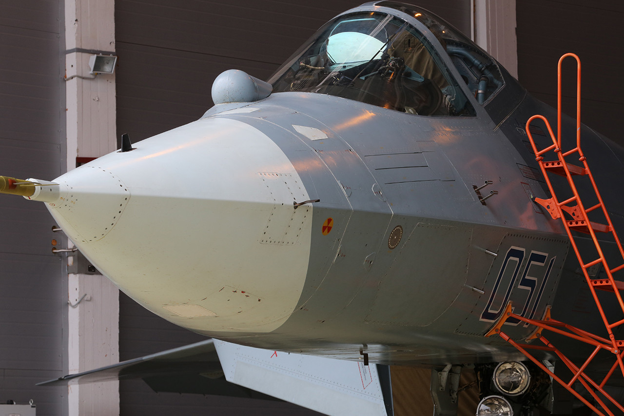
Ew... i noticed people got their OCD up seeing that 510 image. Saw some people make a fuss of it in facebook and twitter.
I wonder why all the power to scrutinize those screws not diverted into something more productive like actually agreeing on how one should present result of his/her RCS estimate.
I wonder why all the power to scrutinize those screws not diverted into something more productive like actually agreeing on how one should present result of his/her RCS estimate.
Don't look at other "more" stealthy airplanes up close or you'll be disappointed.
People, these are machines that fly who knows how high and fast, on different weather, pressures, vibrations, left out in the open, out on top of a carrier, etc. What do you want? butter smooth skin and no panel lines? How are they going to work on them? Do you want the maintenance crews to walk around with spray paint and body filler every time the thing lands?
https://www.f-16.net/forum/download/file.php?id=29316&sid=236b2aa75653f607991f8f3a8062c108&mode=view
View: https://twitter.com/i30mki/status/1156486392328798208?lang=frPeople, these are machines that fly who knows how high and fast, on different weather, pressures, vibrations, left out in the open, out on top of a carrier, etc. What do you want? butter smooth skin and no panel lines? How are they going to work on them? Do you want the maintenance crews to walk around with spray paint and body filler every time the thing lands?
Last edited:
Just look at production plane #01, before you jump to such absurd conclusion.
Well, to be honest, one could start with the CNS. He was shown in 2019.
Although sometimes it is surprising that they cannot show the model of the serial appearance. Secrecy is good, but you shouldn't forget about marketing either.
tequilashooter
ACCESS: Top Secret
- Joined
- 1 January 2021
- Messages
- 699
- Reaction score
- 901
Well that got me by surprise, its like that one time the Su-57 was accused of having bulb shapes compared to the elongated bulb thing on the F-35.People, these are machines that fly who knows how high and fast, on different weather, pressures, vibrations, left out in the open, out on top of a carrier, etc. What do you want? butter smooth skin and no panel lines? How are they going to work on them? Do you want the maintenance crews to walk around with spray paint and body filler every time the thing lands?

Faith in aircraft restored I guess.
Firefinder
ACCESS: Top Secret
- Joined
- 5 October 2019
- Messages
- 1,223
- Reaction score
- 2,300
It should also noted that that image of the SU57 wing screws is like one of this imagines I have seen of the SU57...
3 years ago.
I have a feeling that that is of one of the pre-production models during a test flight.
3 years ago.
I have a feeling that that is of one of the pre-production models during a test flight.

Firefinder
ACCESS: Top Secret
- Joined
- 5 October 2019
- Messages
- 1,223
- Reaction score
- 2,300
Ah so one of the ones that Russia said leave the stealthing out to save costs cause we want to see if it can even fly and drop weapons.Yes, it's one of the prototypes.
Eyeah figures.
- Joined
- 2 January 2006
- Messages
- 4,147
- Reaction score
- 7,740
Similar threads
-
-
WEarly Stealth? 'Means for altering the reflection of radar waves' (US 2436578)
- Started by Wingknut
- Replies: 2
-
 Design Challenge: Lightweight Multirole Fighter (LMF)
- Started by VTOLicious
- Replies: 507
-

-
