Understanding and calculating exhaust thrust

Some interesting things about the Republic Rainbow utilizing exhaust thrust.
View attachment 693821
Instead of dumping the waste gate exhaust off to the side like on the P-47, the waste gate gas was fed into the turbo exhaust. In this way all of the exhaust gas came out the same exit giving a pretty significant boost at lower altitudes. Here the dotted line is the dumped exhaust and solid the recombined exhaust.
View attachment 693822
A variable area exit was used to further boost the exhaust thrust.
View attachment 693820
Lastly, a comparison between the Rainbows installation and a 'typical' one. There is a typo in the net BHP on the right column; it should be 2409 not 4209.

source; https://www.emerald.com/insight/content/doi/10.1108/eb031588/full/html

Highly interesting! And thanks for clearing up this typo thing ...
 
Cessna 310s use a jet tube (forget the proper name) that takes the exhaust gasses and uses them to help draw air through the cowling, which helps cool the engines.

It's possible to do the same for a big radial, just means a physically longer engine installation or taking up additional space in the fuselage or nacelles for the parts.
It is called an augmentor exhaust. I believe the Convair 240 / 340 /440 series of airliners used augmentor exhaust setup on their R2800 installations
 
It is called an augmentor exhaust. I believe the Convair 240 / 340 /440 series of airliners used augmentor exhaust setup on their R2800 installations
Thank you!

So frustrating to forget the proper names of things... At least this time I could remember a synonym and how it worked!
 
Hi,

It is called an augmentor exhaust. I believe the Convair 240 / 340 /440 series of airliners used augmentor exhaust setup on their R2800 installations

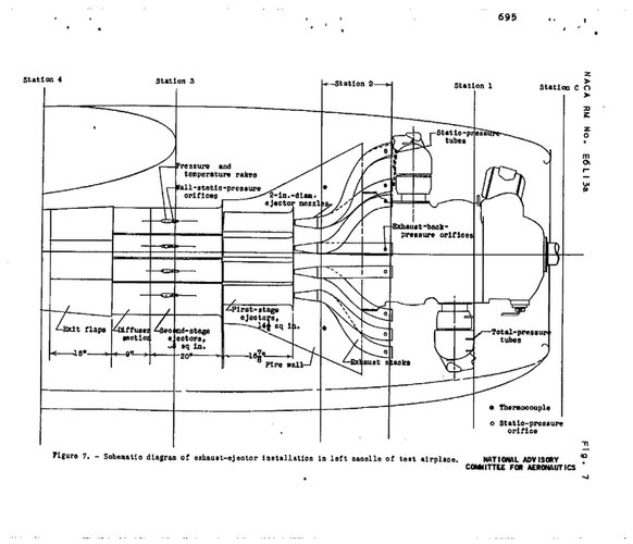
I believe NACA RM E6L13a calls a generally similar system an "exhaust-ejector installation", but of course there might be some technical differences to the Convair system, or just a different terminology between NACA and Convair.

Here's a drawing from the NACA memorandum ...

naca-rm-e6l13a Exhaust Ejectors.jpg

Regards,

Henning (HoHun)
 
Hi,


I believe NACA RM E6L13a calls a generally similar system an "exhaust-ejector installation", but of course there might be some technical differences to the Convair system, or just a different terminology between NACA and Convair.

Here's a drawing from the NACA memorandum ...

View attachment 711740

Regards,

Henning (HoHun)
That's a step more complex than in the 310s, but is probably needed for the total mass airflow needed for a big radial. The 310s only have a single stage ejector, not a two stage ejector.
 
The FW 190 used a driven fan and not ejector cooling, the Sea fury might have relaight on that.

Tatra used it also in production cars, but this was a very noisy solution..
 
The FW 190 used a driven fan and not ejector cooling, the Sea fury might have relaight on that.

Tatra used it also in production cars, but this was a very noisy solution..

The FW 190 used it additionally to the fan. Have a look at the openings behind the exhaust tips.
Tatra: Not at production cars, just at racing/rally versions of the coupe and at single seaters.
 
Once you start doing headers and especially once you get turbochargers involved on the whole engine instead of short stacks on each cylinder, you can get much simpler data to work with. Smoother pulses.

If I ever won the lottery, I'd build a new Pond Racer and run it with a pair of 4-rotor Wankels with a single stupid-huge turbo on each one to make over 1500hp at relatively low RPM for a Wankel. Run the engines at about 7700rpm, props at 2200rpm. Intake flow volume for 7700rpm is going to be on the order of 10.4L/revolution (~60inHg manifold pressure/15psi boost), 1335L/sec. Air is 1.23 grams/liter at sea level, so 1.641kg/sec air flow rate. Mixture is going to be about 8.5:1 or richer, Wankels need to run very rich and this is for E85. At 8.5:1 mixture ratio, that will be 193grams/sec of fuel.

Makes a total of ~1.834kg/sec mass flow rate as a low estimate, it may take 50% more mass flow (at 30psi boost) to get the power numbers I want.
 
Hi Scott,

If I ever won the lottery, I'd build a new Pond Racer and run it with a pair of 4-rotor Wankels with a single stupid-huge turbo on each one to make over 1500hp at relatively low RPM for a Wankel. Run the engines at about 7700rpm, props at 2200rpm. Intake flow volume for 7700rpm is going to be on the order of 10.4L/revolution (~60inHg manifold pressure/15psi boost), 1335L/sec. Air is 1.23 grams/liter at sea level, so 1.641kg/sec air flow rate. Mixture is going to be about 8.5:1 or richer, Wankels need to run very rich and this is for E85. At 8.5:1 mixture ratio, that will be 193grams/sec of fuel.

Sounds like you might enjoy the "Engine Simulator":
View: https://www.youtube.com/watch?v=XbvsdLAzZes


The 2D simulator is free and can be downloaded here: https://github.com/Engine-Simulator/engine-sim-community-edition

The author is working on a more sophisticated 3D version that will be payware.

Be warned that the stated goal is "only" to generate realistic engine sounds. The author remarked that he gets some fairly realistic power and torque curves from the simulator anyway. He also stated, "Quite possibly the dumbest project I've ever undertaken", but I totally disagree! :-D

Regards,

Henning (HoHun)
 
The FW 190 used it additionally to the fan. Have a look at the openings behind the exhaust tips.
Tatra: Not at production cars, just at racing/rally versions of the coupe and at single seaters.
Tatra definately used this cooling method also on production cars (https://archive.commercialmotor.com/article/24th-november-1961/45/air-cooling-by-exhaust-ejector)

Is there any reference for the ejector cooling of the FW19ß and that it produced a significant cooling effect?
 
Hi Basil,

The FW 190 used it additionally to the fan. Have a look at the openings behind the exhaust tips.

Are you sure this is in fact designed for ejector cooling? I just had a look at von Gersdorff et al., and they explicitely mention ejector cooling as a feature on the Argus As 411, but not on the BMW 801. There's airflow diagram for the BMW 801 cowling as well, and it doesn't mention the exhausts either.

Regards,

Henning (HoHun)
 
Tatra definately used this cooling method also on production cars (https://archive.commercialmotor.com/article/24th-november-1961/45/air-cooling-by-exhaust-ejector)

Is there any reference for the ejector cooling of the FW19ß and that it produced a significant cooling effect?

Tatra: No, it would gave been be far too loud for a street car.

FW 190: I do not have any numbers about the amount of the cooling air flow support by the exhaust gas but you can clearly see the cooling opening slits directly behind the exhaust nozzle row.
 
Hi Basil,

FW 190: I do not have any numbers about the amount of the cooling air flow support by the exhaust gas but you can clearly see the cooling opening slits directly behind the exhaust nozzle row.

Perhaps you could point to a picture that shows clearly what you mean?

To get a substantial ejection benefit from exhaust gas, the systems are usually quite involved, like the R-2800 example I posted above, or the installation on the Kyushu J7W Shinden illustrated here:


Regards,

Henning (HoHun)
 

While the FW190 engine exhaust definitely was well integrated with a thrust component in the cooling exit flow, it was not a true ejector exhaust. For that you need the exhaust pipes discharging into a convergent / divergent passage forward of the throat to energize the ejector pumping action to pull the cooling flow thru the engine. I am not saying that the FW190 setup didn’t have some positive effect on the cooling flow
 

While the FW190 engine exhaust definitely was well integrated with a thrust component in the cooling exit flow, it was not a true ejector exhaust. For that you need the exhaust pipes discharging into a convergent / divergent passage forward of the throat to energize the ejector pumping action to pull the cooling flow thru the engine. I am not saying that the FW190 setup didn’t have some positive effect on the cooling flow

Ok, maybe it is not a true exhaust ejector in Mackerle's sense but I am not aware of any aircooled aircraft engine installation where you have a convergent-divergent system for the combined flow of exhaust gas / cooling air. However, the flow of the exhaust stream over openings / louvers contributes to the suction of the cooling air out of the engine compartement on several late war radial engine installations. The Fw 190 was one of the first examples with such a system that entered service.
 
Last edited:
Ok, maybe it is not a true exhaust ejector in Mackerle's sense but I am not aware of any aircooled aircraft engine installation where you have a convergent-divergent system for the combined flow of exhaust gas / cooling air. However, the flow of the exhaust stream over openings / louvers contributes to the suction of the cooling air out of the engine compartement on several late war radial engine installations. The Fw 190 was one of the first examples with such a system that entered service.
Cessna 310 for a current example of ejector exhausts.

Those louvers on the FW190 are basic cowl flaps. And are likely too small in area compared to the engine's heat output. Look at how much area the radial engine nacelles have on US planes.
 
Cessna 310 for a current example of ejector exhausts.

Those louvers on the FW190 are basic cowl flaps. And are likely too small in area compared to the engine's heat output. Look at how much area the radial engine nacelles have on US planes.

Yes, they are cowl flaps, augmented by the exhaust stream. The installation of the Bristol Centaurus in the Tempest / Fury (just one example) was similar although there were no adjustable louvers afaik.
The nacelles on US planes like the P-47 did not utilize exhaust augmentation of the cooling air flow (they had a turbocharger) so the area had to be larger. The turbocharged version of the BMW 801 could of course also not use the augmentation and it had an enlarged cooling fan.
 
Last edited:
Yes, they are cowl flaps, augmented by the exhaust stream. The installation of the Bristol Centaurus in the Tempest / Fury (just one example) was similar although there were no adjustable louvers afaik.
The nacelles on US planes like the P-47 did not utilize exhaust augmentation of the cooling air flow (they had a turbocharger) so the area had to be larger. The turbocharged version of the BMW 801 could of course also not use the augmentation and it had an enlarged cooling fan.
I'm having a very hard time picturing how exactly the exhaust augments the air flow with no convergent/divergent tubes and quite frankly dumping the exhaust well forward of the louvers in general.
 
I'm having a very hard time picturing how exactly the exhaust augments the air flow with no convergent/divergent tubes and quite frankly dumping the exhaust well forward of the louvers in general.

Well, it's relatively simple fluid physics. The fast stream of gases flowing over an opening creates a negative pressure and thus a suction effect behind the opening. This effect is used in many ways, for example generating an air cooling stream for the oil cooler of the Turbomeca turboshaft of the Alouette and Gazelle helicopters where you can see a smaller tube attached to the larger exhaust tube. In the case of Mackerle's concept you have a concentric layout which is perhaps the most efficient one. Btw, the oil cooler of the BMW 003 and He 011 used a similar system with the cooling outlet in the center of the jet stream.
 
Last edited:
Well, it's relatively simple fluid physics. The fast stream of gases flowing over an opening creates a negative pressure and thus a suction effect behind the opening. This effect is used in many ways, for example generating an air cooling stream for the oil cooler of the Turbomeca turboshaft of the Alouette and Gazelle helicopters where you can see a smaller tube attached to the larger exhaust tube. In the case of Mackerle's concept you have a concentric layout which is perhaps the most efficient one. Btw, the oil cooler of the BMW 003 and He 011 used a similar system with the cooling outlet in the center of the jet stream.
That's the problem: I don't think those exhaust gasses are going all that fast while the plane is in motion.
 
That's the problem: I don't think those exhaust gasses are going all that fast while the plane is in motion.

They are fast; the pulses are in the sonic/supersonic velocity regime. Usable exhaust thrust gets higher with aircraft speed.
 
They are fast; the pulses are in the sonic/supersonic velocity regime. Usable exhaust thrust gets higher with aircraft speed.
I've put my hands into the exhaust of a running R985 before. Cold morning times cold hands. Not supersonic in the slightest, even with the engine at full RPM.
 
I've put my hands into the exhaust of a running R985 before. Cold morning times cold hands. Not supersonic in the slightest, even with the engine at full RPM.
Try the same with a wartime high performance aircraft engine with ejector exhaust nozzels.
 
Hi Basil,

F119Doctor's link (above) shows the louvers in detail. They could be adjusted according to cooling needs. Of course you can see them on all photos were the exhaust section is illustrated.

Ah, thanks - now I see what you mean. These louvres actually were not originally part of the Fw 190's cooling system as designed, they were a tweak brought in during early production to improve the initially unsatisfactory cooling. The original reason for the Fw 190 cowling to be designed so tightly fitting was in fact the use of a cooling fan, the louvres were added on as an afterthought only.

Regards,

Henning (HoHun)
 
Last edited:
Back on the subject of exhaust thrust, an ejector exhaust system is taking the energy of the high velocity engine exhaust and transferring it into the cooling flow, making for a larger mass flow at a lower overall velocity, somewhat like raising the bypass ratio of a turbofan engine. Neglecting the improved cooling knock on effects on drag, it would seem that ejector cooling would have decreasing thrust impact as the airspeed increases. Not sure if propeller driven aircraft ever get fast enough for ejector exhaust to become a net negative.
 
Back on the subject of exhaust thrust, an ejector exhaust system is taking the energy of the high velocity engine exhaust and transferring it into the cooling flow, making for a larger mass flow at a lower overall velocity, somewhat like raising the bypass ratio of a turbofan engine. Neglecting the improved cooling knock on effects on drag, it would seem that ejector cooling would have decreasing thrust impact as the airspeed increases. Not sure if propeller driven aircraft ever get fast enough for ejector exhaust to become a net negative.
If they used a full convergent/divergent nozzle for the exhaust to maximize velocity going into the ejector stacks (clear to supersonic), I don't believe any propeller aircraft would be able to go fast enough to get the overall effect into a net negative.

But all the pictures I've seen have been only converging pipes at most.
 
Hi,

I believe NACA RM E6L13a calls a generally similar system an "exhaust-ejector installation", but of course there might be some technical differences to the Convair system, or just a different terminology between NACA and Convair.

I posted a summary statement from the report that also mentions the effect on thrust here:


A more detailed discussion can be found in the report.


Regards,

Henning (HoHun)
 
Hi,


I posted a summary statement from the report that also mentions the effect on thrust here:


A more detailed discussion can be found in the report.


Regards,

Henning (HoHun)
You are probably aware of Focke Wulf's calculations from 1939 where they used information from a patent "Zwangskühlung von Flugmotoren durch Auspuffenergie"? They figured out that not just the fan can be removed from the BMW 139 (saves max of 66 hp now not needed to drive it, but also no need to make it), but also there is also increase of propulsive power equaling 94.5 HP at max speed of above 650 km/h on the Fw 190 - all due to the use of exhaust energy to help out.

(my comment - obviously, the BMW still required the fan cooling, but layout of exhaust stacks was probably not an ... accident)
 
Hi Tomo,

You are probably aware of Focke Wulf's calculations from 1939 where they used information from a patent "Zwangskühlung von Flugmotoren durch Auspuffenergie"? They figured out that not just the fan can be removed from the BMW 139 (saves max of 66 hp now not needed to drive it, but also no need to make it), but also there is also increase of propulsive power equaling 94.5 HP at max speed of above 650 km/h on the Fw 190 - all due to the use of exhaust energy to help out.

Actually I'm not, but I'd be very interested to learn more about it! Do you happen to have a link, in case it can be found online?

Regards,

Henning (HoHun)
 
Hi Tomo,

At BAMA, file R 3/3708.

Thanks a lot for the reference, quite an interesting file! To my surprise, there's also stuff on the Fw 187 in there, despite that not being mentioning in the title.

With regard to the calculations you mentioned, these describe an alternative solution that was not actually implemented in Fw 190 production. Blatt 3 makes it clear that the radiator fan was to be eliminated, and Figure 1 and 2 show that a regular injector was used. It's sort of difficult to see in the drawing because only the exhaust ends are shown, but if you look at the "14 Rohre" caption, there's a tubular section that combines the centrally injected exhaust gases with the circumferentially ducted engine cooling air to form an injector.

These tubular injectors are sealed on the outside against the engine cowling, so it's a different arrangement from the standard Fw 190 exhausts, where the exhaust tubes exit the cowling with an air gap all around them, and the engine cooling air exiting the cowling through the gaps with no guiding tubes.

Regards,

Henning (HoHun)
 

Similar threads

Back
Top Bottom