
Calculating the exhaust thrust for a mechanically supercharged engine is impossible without some thermodynamic skills. It is relatively easy for turbocharged engines (simple rocket science) because of the stationary flow process through a simple nozzle, but in a purly mechanically charged engine the exhaust process is an open flow process. The exhaust velocity and the mass flow between the opening and closing of the exhaust valves is not even close to being constant, which makes it quite demanding for calculations. If you have access to 1-d engine simulation programs like GT Power or Boost, it is a relatively easy task. Without that it will be almost impossible to calculate manually unlike you are a super really extremely capable in integrating complex equations. However, with Mathlap, Origin or even Exel you could find a decent solution (with using a lot of assumptions and simplifications).
If somebody is drawing nice lines which show no connection to the engine power, you can be sure that he never really calculated he exhaust thrust!
So, this is your input data what you definitely need for an estimation of the exhaust thrust:
Cylinder:
p,t,V at the time the exhaust valve opens
dV/dt (cylinder volume over time/crank angle)
exhaust valve:
equivalent isentropic opening area over time/crank angle (dA/dt):
valve lift curve, flow curve
Ejector:
-Volume between exhaust valve and Laval nozzle
-cross section area
-smalles area (Laval cross section) of the Laval nozzle
-Expansion ratio of the Laval nozzle
-athmospheric pressure
The following simplifications would need to be done to make it manageable:
-exhaust gas will be an ideal gas (it is not..)
-no heat losses to the walls (which will give quite an error….)
-no gas friction losses
Thermodynamic model:
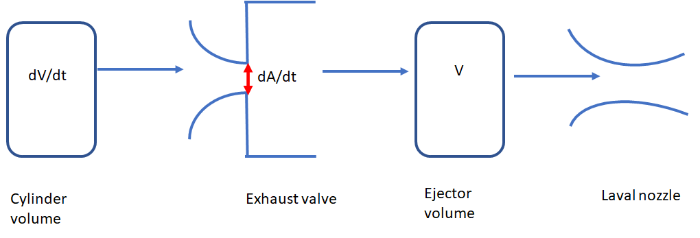
Basically, the exhaust model can be described by the cylindervolume, the exhaust valve, a fixed intermediate volume between the valve and the Laval nozzle and the Laval nozzle itself (see my pic). The exhaust valve can be described as a convergent isentropic nozzle with a varying cross section (according to the valve lift curve) and an unsteady cross section enlargement from the isentropic cross section to the cross section area of the Ejector.
The exhaust process must be split into several simplified steps. Depending on the flight height and the geometry of the ejector, the Laval conditions at the exhaust valve or the Laval nozzle can be reached in a different sequenz:
The exhaust valve opens and at that time the pressure in the ejector volume is atmospheric
The gas will reach the Laval condition in the equivalent exhaust nozzle cross section. The ejector pressure has no influence on the exhaust valve mass flow. The pressure inside the ejector will rise until the system reaches the Laval condition in the Laval nozzle (Mach=1).
There is no shortcut to this calculations and you should not believe that somebody did these type of calculations without explaining how he did it and which boundary conditions and tools he used.
Some thought about the ejector design goals:
For producing a maximum amount of thrust, the pressure before the Laval nozzle must be as high as possible. The downside of that, is that an increased exhaust pressure will cause losses in crank power, but you need to keep in mind, that as long as we have a Laval pressure ratio over the exhaust valve, the back pressure will not have any impact on the engine. As most thrust will be produced around BDC when the cylinder pressure is high and the exhaust valve is allready halfway open, an ejector should be designed with a Laval cross section which will rise the pressure in the ejector at that point so high that it just allows to keep the pressure drop over the exhaust valve just in Laval condition of only short time below that.
Like always a fixed geometry can only work at its optimum at one point or one operational line. With very little back pressure at great height, the emphasis should be on producing less back pressure, since the pressure ratio over the Laval nozzle will nearly always produce high exhaust velocities and the shrinking propulsion efficiency will lower the benefit of additional back pressure. A large expansion ratio of the Laval throttle will help in great height but reduce the thrust in low heights (same is true for rocket nozzles). You see, rocket science is included in combustion engine technology, but its just a small part of it….
Sleeve valve engines with their fast exhaust opening, are far more efficient in producing exhaust thrust, this is often overlooked.
If somebody is drawing nice lines which show no connection to the engine power, you can be sure that he never really calculated he exhaust thrust!
So, this is your input data what you definitely need for an estimation of the exhaust thrust:
Cylinder:
p,t,V at the time the exhaust valve opens
dV/dt (cylinder volume over time/crank angle)
exhaust valve:
equivalent isentropic opening area over time/crank angle (dA/dt):
valve lift curve, flow curve
Ejector:
-Volume between exhaust valve and Laval nozzle
-cross section area
-smalles area (Laval cross section) of the Laval nozzle
-Expansion ratio of the Laval nozzle
-athmospheric pressure
The following simplifications would need to be done to make it manageable:
-exhaust gas will be an ideal gas (it is not..)
-no heat losses to the walls (which will give quite an error….)
-no gas friction losses
Thermodynamic model:
Basically, the exhaust model can be described by the cylindervolume, the exhaust valve, a fixed intermediate volume between the valve and the Laval nozzle and the Laval nozzle itself (see my pic). The exhaust valve can be described as a convergent isentropic nozzle with a varying cross section (according to the valve lift curve) and an unsteady cross section enlargement from the isentropic cross section to the cross section area of the Ejector.
The exhaust process must be split into several simplified steps. Depending on the flight height and the geometry of the ejector, the Laval conditions at the exhaust valve or the Laval nozzle can be reached in a different sequenz:
The exhaust valve opens and at that time the pressure in the ejector volume is atmospheric
The gas will reach the Laval condition in the equivalent exhaust nozzle cross section. The ejector pressure has no influence on the exhaust valve mass flow. The pressure inside the ejector will rise until the system reaches the Laval condition in the Laval nozzle (Mach=1).
- Same as 1, but with supersonic exhaust in the Laval nozzle and further increasing pressure in the ejector volume until the pressure becomes so high, that pressure drop over the exhaust valve cross section is below the Laval pressure, This goes on until (whatever comes first) the Laval pressure is no longer reached at the Laval nozzle, or the pressure inside the ejector volume fell so much, that we regained the Laval conditions at the corresponding exhaust cross section.
- In case, the pressure relation in corresponding exhaust cross section equates to the Laval conditions again, this goes on until the pressure drop in the Laval nozzle or the corresponding exhaust cross section is less than the Laval conditions.
- If the pressure difference over the corresponding exhaust cross section drops under the Laval conditions but the pressure ratio in the Laval nozzle is still at Laval condition, go on until it reaches the Limit of the Laval condition at the nozzle
- Even below the Laval condition, some exhaust thrust is being produced, on this case an expansion in the Laval nozzle will slow the exhaust down, so that in many cases this will be quite insignificant.
There is no shortcut to this calculations and you should not believe that somebody did these type of calculations without explaining how he did it and which boundary conditions and tools he used.
Some thought about the ejector design goals:
For producing a maximum amount of thrust, the pressure before the Laval nozzle must be as high as possible. The downside of that, is that an increased exhaust pressure will cause losses in crank power, but you need to keep in mind, that as long as we have a Laval pressure ratio over the exhaust valve, the back pressure will not have any impact on the engine. As most thrust will be produced around BDC when the cylinder pressure is high and the exhaust valve is allready halfway open, an ejector should be designed with a Laval cross section which will rise the pressure in the ejector at that point so high that it just allows to keep the pressure drop over the exhaust valve just in Laval condition of only short time below that.
Like always a fixed geometry can only work at its optimum at one point or one operational line. With very little back pressure at great height, the emphasis should be on producing less back pressure, since the pressure ratio over the Laval nozzle will nearly always produce high exhaust velocities and the shrinking propulsion efficiency will lower the benefit of additional back pressure. A large expansion ratio of the Laval throttle will help in great height but reduce the thrust in low heights (same is true for rocket nozzles). You see, rocket science is included in combustion engine technology, but its just a small part of it….
Sleeve valve engines with their fast exhaust opening, are far more efficient in producing exhaust thrust, this is often overlooked.


")


