Cooling fans + air-cooled radials & cooling

Pasoleati

I really should change my personal text
Joined
29 June 2012
Messages
496
Reaction score
167
Question: Why did so many companies stick to the utterly inefficient circumferential cooling flaps in their radial installations when the far better system of longitudinally sliding gills existed? Quite a many aircraft with air-cooled radials suffered from overheating in especially high-power climbs and the drag penalty of the aforementioned outward-opening cowl flaps could be over 50 km/h. In many aircraft opening those cowl flaps also affected visibility, handling and stalling.

Cooling fan + sliding gills would have reduced the drag a lot while allowing higher outputs especially at slower speed conditions.
 
Radial engine cowlings experienced rapid development between 1914 and 1945. Consider that in 1914, only a few radial engines even had cowlings. Many flew better without cowlings because of the difficulty of cooling spinning rotary engines at airspeeds of less than 100 miles per hour.
Radial engines did not really become successful until the 1920s.
Townsend invented ring cowlings to help cool cylinder heads.
Then NACA invented long-chord cowlings that reduced drag.
Then Curtiss invented cowlings that ejected cooling air straight back along the sides and bottom.
Eliminating flaps from the tops of cowlings really only occurred during WW2 and that was primarily to improve pilot visibility when landing-on ships (see Chance-Vought F4U Corsair).
The additional cooling fans and sliding cowl flaps were only introduced on Focke-Wolf's 190. Few other radials ever got cooling fans.
What you described was the ultimate in radial cowlings and only a few manufacturers adopted those cowlings during WW2. Post-war, all development monies went into developing jet engines.
 
I wonder what would happen if you installed extra cooling fan(s) down-stream of the cylinders for ground-cooling???????
 
The flaps sticking out create a low pressure area behind them that can help to move the air through the engine. This is likely more than worth the additional drag in climb, which is when cooling is probably most critical.
 
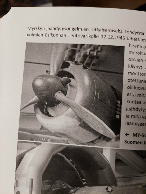
For what it's worth, the propeller spinner of the production version of the Finnish VL Myrsky II fighter plane, introduced in 1944, may well have been fitted with small fins to improve engine cooling.
Yes, it had 3 small blades fitted on the prop spinner. The Myrsky suffered a great deal from overheating. One experiment featured a cut cone-shaped collar mounted behind the propeller and around the reduction gear housing guiding the cooling airflow. The device reduced CHT by no less than 40 deg. C.

Do you have a picture of that fancy spinner?
I am trying to imagine an aft-facing cone to smooth airflow aft of the usual external spinner?????????
 
Hi Pasoleati,

Question: Why did so many companies stick to the utterly inefficient circumferential cooling flaps in their radial installations when the far better system of longitudinally sliding gills existed? Quite a many aircraft with air-cooled radials suffered from overheating in especially high-power climbs and the drag penalty of the aforementioned outward-opening cowl flaps could be over 50 km/h. In many aircraft opening those cowl flaps also affected visibility, handling and stalling.

I suspect the radially-arranged flaps simply were the standard solution at the time, meaning they could be implemented with the least amount of engineering hours and management attention.

Coincedentally, I just came across NACA RM No. E6L13a "Flight Comparison of Performance and Cooling Characteristics of Exhaust-Ejector Installation with Exhaust-Collector-Ring Installation", showing the use of the exhaust gases to "pull" cooling air into the cowling.


Flight and ground investigations have been made to compare an exhaust-ejector installation with a standard exhaust-collector-ring installation on air-cooled aircraft engines in a twin-engine airplane. The ground investigation allowed that, whereas the standard engine would have overheated above 600 horsepower, the engine with exhaust ejectors cooled at take-off operating conditions at zero ram. The exhaust ejectors provided as much cooling with cowl flaps closed as the conventional cowl flaps induced when full open at low airspeeds. The propulsive thrust of the exhaust-ejector installation was calculated to be slightly less than the thrust of the collector-ring-installation

Regards,

Henning (HoHun)
 
It has already been mentioned here the reason, but I will elaborate a bit. You have to get a certain amount of air through the cooling fins. There are a couple of ways to do this, but it is more than just having an air source and an exit for that air. The air source needs to have a high total pressure that then gets drawn through the baffles and then the cooling fins. You can have a large opening to have that air push itself through, but then you are going to have unacceptable losses at cruise speed. If you then make the inlet sized for cruise, then it will have issues in low speed high power conditions such as takeoff and climb.

Cowl flaps help this by causing a pressure loss just aft of the flap itself. It does this by actually being "inefficient" and having flow losses. This then reduces the pressure at the exit of the cooling air, and creates a larger pressure differential across the cylinders drawing more air through.

If you were only to open a slot, this would not change the pressure differential across the cylinders and would not increase the cooling flow despite the larger area unless the initial area was not sufficient causing an internal flow loss in the cooling system and you would reduce this by opening the area. If this were the case, though, that would likely mean that you would get inlet spillage around the cowl entrance and you would be dealing with those aero issues there.

The cooling fan itself, is extra weight that is not always needed and will always be taking some engine power to work.

As is in almost every engineering problem, though, you need an entire set of tools to find the best compromise for the situation you are designing for. Engineering is not about creating the best thing, it is about creating something that finds the right combination of compromises to achieve your end goal.
 
Regarding the power requirement of the fan: how many percent of the power? For comparison: if the difference in speed between cowl flaps closed and full open is 10 %, one might want to do the math how big a difference in power that means. Or if a pilot manual recommends auto-rich for cruising (entailing a 15 % increase in fuel consumption) instead of opening cowl flaps fully, it should be quite clear how inefficient those outward opening cowl flaps are and in comparison the power taken by a fan is akin to the "suffering" experienced by a female elephant due to having been had a male ant.
 
Regarding the power requirement of the fan: how many percent of the power? For comparison: if the difference in speed between cowl flaps closed and full open is 10 %, one might want to do the math how big a difference in power that means. Or if a pilot manual recommends auto-rich for cruising (entailing a 15 % increase in fuel consumption) instead of opening cowl flaps fully, it should be quite clear how inefficient those outward opening cowl flaps are and in comparison the power taken by a fan is akin to the "suffering" experienced by a female elephant due to having been had a male ant.
The problem is that as in any engineering problem... it depends. Cowl flaps are something that causes drag to the system generally in climb or takeoff conditions where the velocity is lower, therefore the power lost is at this point relatively low as it is a v^3 relation. But when the aircraft is in cruise, it will be no aero drag to the airframe when closed. They also allow for some intermediate positions for corner point conditions where you may need more cooling than when closed, so they can be opened only slightly with a minor penalty.

In the case of a fan, it is always there even when you do not need it. So it will generally be designed for the worst case condition which is likely climb and takeoff, but not likely the case at altitude while cruising. So in this case, you will have power extraction while you do not need it, and the only way to throttle it is by actually changing the engine throttle. It is a bit of a brute force tool. The FW-190A models with the BMW engine was known to have engine cooling problems, so this was likely a very brute force tool to help this issue, and when they went to the D and the Ta-152 engine installations with the anular cooling this fan went away and cowl flaps came in. Better said, the BMW-801 generally had cooling problems, and likely was due predominantly with the exhaust valves and the lack of high temp materials at the time in Germany. I would have to go back to @Calum Douglas and his book to confirm this.

Without doing a full aircraft analysis for this feature, I would guess that the cowl flaps are the more efficient solution across the flight envelope. If not, then you would find that more would have gone to the cooling fan. Designs tend to converge towards a solution when it is the most efficient path balancing the rest of the needs of the system.
 
Despite the prop consumes energy, the additional trust might outweigh the power losses by the fan. The air is heated after the fan and will expand, so that the velocity of the out streaming air is increased without additional fan work. If the air speed of the exhausting cooling air is higher than the plane speed, trust will be generated. For sure, the system must be defined for very high efficiency and internal streamlining to achieve this, also the amount of cooling flow has to be minimized.

You should notice, that the Americans adapted the fan for the Bearcat and the Republic Rainbow, they propably got the inspiration from the FW-190.
 
You should notice, that the Americans adapted the fan for the Bearcat and the Republic Rainbow, they propably got the inspiration from the FW-190.
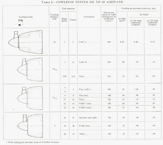
NACA did a decent amount of research into cooling fans on radials prior to the FW-190. Its quite likely that FW/BMW took inspiration from the US and not the other way around.
 
The idea of using a fan itself is not very outstanding (nearly all aircooled cars used them before), but its about how design the drive train and cowling to make it work effeciently. To proove if the design of the FW-190 was inspired by NACA research one needs to see these papers and compare the FW-190 design with them. Using a fan has pos and cons and it was not a popular item in planes until the FW-190 prooved that it works and makes sense. If the NACA researchers had the same conclusion (quite likely without beeing able to work on a elaborate design) we would have seen cooling fans on American planes much earlier.
 
The following link might be of interest... https://ww2aircraft.net/forum/threads/fan-cooling-of-radials.54754/

For what it's worth, the propeller spinner of the production version of the Finnish VL Myrsky II fighter plane, introduced in 1944, may well have been fitted with small fins to improve engine cooling.

This July 1944 article describes in great detail why cooling by a (geared) fan may be advantageous in total horsepower consumption compared to a non-fan installation of a radial engine.
 
I think this was already linked before, unfortunately, the last part is missing. In these trials they didn’t use heated grids as cylinder replacement, the so that the additional trust by heating the coolant air couldn’t be measured and wasnt considered. Also, I didn’t find any hint, that they calculated the exhaust velocity in conjunction with the temperature which would be crucial for the trust vs. power requirement balance. Maybe it was that missing part, which led Focke Wulf to a different conclusion than Wright.
 
Or perhaps engineering is all about compromises and you have to pick and choose what you need/want. BMW had different priorities than American companies, possibly because of the goofy oil cooler on the 190.
fan cooling.png
 
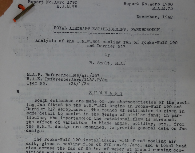
The Royal Aircraft Establishment made a fairly comprehesive study of the Fw190 fan in late 1942.

If someone persuades me I might upload it to my website at some point. As usual, "is it better" comes with caveats.

It IS advantageous under many circumstances, but, it is also perfectly possible to design a fan assisted design which will be worse than pure "dynamic" air cooled if you get lazy. The key advantages are that the fan enclosed in a suitable duct, can be made about 10% more efficient than a propellor, and that the fan, being geared, is able not only to satisfy all ground running cooling problems but also to positvely influence performance at normal flight speeds.

Of course, "it depends" is the key phrase to keep in mind.

1646409412022.png
 
I think this was already linked before, unfortunately, the last part is missing. In these trials they didn’t use heated grids as cylinder replacement, the so that the additional trust by heating the coolant air couldn’t be measured and wasnt considered. Also, I didn’t find any hint, that they calculated the exhaust velocity in conjunction with the temperature which would be crucial for the trust vs. power requirement balance. Maybe it was that missing part, which led Focke Wulf to a different conclusion than Wright.
Full report:
 

Attachments

  • Fan Cooling 1944 1JUL and 1AUG FW 190_Aviation Magazine_Archive_org 3.pdf
    1.3 MB · Views: 31
@Basil : thanks for the PDF!

I don’t think the oil cooler was goofy. Besides the aerodynamic, you always need to keep in mind how vulnerable the airplane is and the bullet proof cowling of the FW-190 protected the oil cooler very well, unlike anything which hangs below the fuselage. The fan might itself have been a protection for the engine against bullets (does anybody know?), so that the plane must have been very well secured against to frontal attacks. The oil cooler was also fed by the fan and didn’t disturb the airflow to the cylinder or increase the frontal area.

The overall drag must have been surprisingly low for an air-cooled fighter plane:

View: https://www.youtube.com/watch?v=9wb5YzVbTNo&ab_channel=Greg%27sAirplanesandAutomobiles
 
The overall drag must have been surprisingly low for an air-cooled fighter plane:
Why don't you calculate it instead of speculating?
Or, better, find the test data.

What was the zero-lift drag coefficient of the radial-engined FW190 variants? How did it compare to that of other radial-engined fighters? The vast majority of single-engined WW2-era fighters had zero-lift drag-coefficients between about 0.020 and 0.024, with little difference between radial and liquid-cooled aircraft.

Without actual data, any talk about the superiority -- or not -- of the FW190's cooling system is nonsense.
 
Production Bearcats did not have a cooling fan. Rainbow and B-36 did have cooling fans.

Fans were required on the B-36 due to lack of any prop slipstream when the airplane was stationary or taxiing. In this case the fans were an artifact of the pusher configuration.

Was the Bearcat initially designed to have a fan? I've never seen any reference to one.

And please correct me here if I am mistaken, but if I recall correctly, the FW-190 wasn't initially designed with a fan either. The prototype had a spinner intake for cooling air, but the design was fraught with cooling issues that were not completely corrected by the reversion to a "NACA"-type cowl, thus the fan.

I agree 100 percent with 1635yankee; without actual data, any claim one way of the other is mere assumption. It does seem to me, however, that a lot of folks are willing to assume that a particular solution is superior just because the Germans did it that way.
 
Other than the B-36 and many (likely all) piston-engine helicopters, I used to believe that no US company produced a radial-engine aircraft which relied on fan-cooled engines; I then was informed that some (but not all) Martin Mariner PBM-3s used fan-cooled R-2600s. US engineers certainly knew about fan-cooling, but they were only used on two production airplanes, despite radial engines being used in many applications where both low cooling drag and extended operation at high power settings were important considerations. My personal opinion is that the US aircraft industry was, overall, better at putting radial engines into aircraft than was German industry. In other words, FW's engineers used a cooling fan not because they were better than America's, but because they weren't. The fan was a crutch.
 
there is no need to do the calculations myself because a much more experienced person (David Lednicer) already did that. If you would have watched my video, you would have noticed, that Greg (the producer of the video) quoted that experienced aero dynamist who did exactly that and came to this conclusion. Because of potential copy right violation, it is not directly included in the video, but you can go to the primary source.

Despite that, I’m more into thermodynamics and will do some calculations for trust/power demand/drag of fan cooling and nun fan cooling.

@1635yankee The Republic Rainbow also used cooling fans for the air cooled radials and this was one of the most outstanding and efficient piston aircraft ever. The Americans could use much better Materials than the Germans and weren’t disturbed by frequent bombardments, so they should have been able to built better engines than the Germans, which spend a lot of development work in how to replace materials instead of improving the performance.
 
Last edited:
Other than the B-36 and many (likely all) piston-engine helicopters, I used to believe that no US company produced a radial-engine aircraft which relied on fan-cooled engines; I then was informed that some (but not all) Martin Mariner PBM-3s used fan-cooled R-2600s. US engineers certainly knew about fan-cooling, but they were only used on two production airplanes, despite radial engines being used in many applications where both low cooling drag and extended operation at high power settings were important considerations. My personal opinion is that the US aircraft industry was, overall, better at putting radial engines into aircraft than was German industry. In other words, FW's engineers used a cooling fan not because they were better than America's, but because they weren't. The fan was a crutch.
This is a very truncated view; it seems you have not read the July 1944 report (enclosed above) or Calum's statement. Btw, the XP-47J Superbolt, the fastest Tunderbolt of all, had a fan-cooled R-2800; the same applies to the XP-72 for its R-4360.
 
Last edited:
there is no need to do the calculations myself because a much more experienced person (David Lednicer) already did that. If you would have watched my video, you would have noticed, that Greg (the producer of the video) quoted that experienced aero dynamist who did exactly that and came to this conclusion. Because of potential copy right violation, it is not directly included in the video, but you can go to the primary source.

Despite that, I’m more into thermodynamics and will do some calculations for trust/power demand/drag of fan cooling and nun fan cooling.

@1635yankee The Republic Rainbow also used cooling fans for the air cooled radials and this was one of the most outstanding and efficient piston aircraft ever. The Americans could use much better Materials than the Germans and weren’t disturbed by frequent bombardments, so they should have been able to built better engines than the Germans, which spend a lot of development work in how to replace materials instead of improving the performance.
I used to work with Dave, when he and I were at Sikorsky.

The Republic Rainbow wasn't a production aircraft.
 
Did any engines use a mix?
If the liquid cooling system was down…they could throttle back to air cooling.

Any water cooled radials?
 
What's the matter if the rainbow was a production aircraft or not? It was planed as a production aircraft and built for maximum performance and efficiency
 
there is no need to do the calculations myself because a much more experienced person (David Lednicer) already did that. If you would have watched my video, you would have noticed, that Greg (the producer of the video) quoted that experienced aero dynamist who did exactly that and came to this conclusion. Because of potential copy right violation, it is not directly included in the video, but you can go to the primary source.
I've read all of Lednicers papers and suggest you do the same. Because they don't support what you are claiming.
 
so I found an intresting paper of David Lednicer:


On table one, we see the drag cofficients related to the wetter area. In this regard, the Spitfire has a lower drag coefficient but a higher wetted area than the FW190 A (that one, with the air cooled radial). Since the wetted area related drag coefficient of the FW-190 A is 109.2 % than that of the Spitfire Mark IX but the wetted area is only 88.4 % the absolut drag is about 2 % lower.

I’m not sure about the first column, but I guess that’s the aerodynamic equivalent area, or flat plane area. This result doesn’t fully match the calculations above, but here the difference is slightly higher (FW190 A: 522 ft² Spitfire IX: 540 ft² => 3.3 %)

So Greg was right, the FW190 A has indeed a lower drag than the Spitfire IX
 
Last edited:
The paper says nothing about cooling fans, which is what your original assertion was about. It also shows that the radial engined 190 has the highest CD which is counter to your claim.

You should probably start reading some books instead of watching youtube videos. Raymers aircraft design a conceptual approach is pretty easy to grasp, at least in the first few chapters.
 
@sienar

Still you didn’t get that thing with the reference area. The Cd value in David’s paper is referred to the wetted area and because the Spitfire Mark IX has more wetted area than the FW190, it has a lower cd value despite having a higher absolute drag. If David would have used the frontal area as reference, the Cd value of the FW-190 with its bulkier fuselage would have been lower. Despite that, what really matters is the absolute drag (zero lift drag) and no matter which Cd you are using, the FW190 A has a lower drag than the Spitfire IX.

I guess, David didn’t include a rotating fan in his calculation, if so, the drag of the FW190 would be even lower, because the fan is pushing out the air with power from the engine.

I would recommend you, not to read too many complicate books about aerodynamic before you didn’t understand the fundamentels:

“Notice that the area (A) given in the drag equation is given as a reference area. The drag depends directly on the size of the body. Since we are dealing with aerodynamic forces, the dependence can be characterized by some area. But which area do we choose? If we think of drag as being caused by friction between the air and the body, a logical choice would be the total surface area of the body. If we think of drag as being a resistance to the flow, a more logical choice would be the frontal area of the body that is perpendicular to the flow direction. And finally, if we want to compare with the lift coefficient, we should use the same wing area used to derive the lift coefficient. Since the drag coefficient is usually determined experimentally by measuring drag and the area and then performing the division to produce the coefficient, we are free to use any area that can be easily measured. If we choose the wing area, rather than the cross-sectional area, the computed coefficient will have a different value. But the drag is the same, and the coefficients are related by the ratio of the areas. In practice, drag coefficients are reported based on a wide variety of object areas. In the report, the aerodynamicist must specify the area used; when using the data, the reader may have to convert the drag coefficient using the ratio of the areas." (https://www.grc.nasa.gov/www/k-12/airplane/drageq.html)
 
If David would have used the frontal area as reference, the Cd value of the FW-190 with its bulkier fuselage would have been lower.
Maybe you should email him and ask why he chose to use swet instead of the frontal area

Good luck!
 
Last edited by a moderator:
Its not a qustion of why he choosed which area, its about what it means for the parasitic drag, you still dont understand it!

Is it really a good idea posting someones E-mail in a puplic forum???
 
You had two separate aerodynamists correct you in that thread but you didn't believe them. Since Lednicer is quoted in a youtube video, maybe you'll take his word for it. That is why you should contact him, because you most definitely do not understand the things you think you do.

His email is posted on uiuc airfoil usage and his website - hardly secret or non-public.
 

Similar threads

Back
Top Bottom