In most piston engine powered planes, the cooling air is somehow released by a slit and flows along the fuselage (e.g. in all classic cowlings with flaps of radial engines). With such a design, the warm (=high viscosity) and turbolent air is attached to the fuselage, which will quite certainly increase drag. I believe, a NACA duct might (or might not) also work in reverse and bring a seperation between the outflowing cooling air and the boundary layer. I haven’t seen such a design in any aircraft, but I’m sure someone has tested it, does anybody know?

You are using an out of date browser. It may not display this or other websites correctly.
You should upgrade or use an alternative browser.
You should upgrade or use an alternative browser.
Naca air intake ducts in reverse flow (as outlets)
- Thread starter Nicknick
- Start date
- Joined
- 6 November 2010
- Messages
- 4,224
- Reaction score
- 3,145
Been there, done that: http://www.n56ml.com/nacaducts/ - read last paragraph.
OK, probably not working very efficient. Maybe a boundary layer port like in the cooling of the Bf109 f would be a better approach to keep the cooling air away from the fuselage. NACA might have a better solution somewhere in the archive…
Aeroengineer1
Engineering, not just a job, but a lifestyle :)
- Joined
- 27 January 2008
- Messages
- 119
- Reaction score
- 97
I could see the principles of this being able to work. Though you would likely want something like a vortex generator (in the more classical sense) that was exposed to the flow allowing for both a low pressure behind them as well as a mixing and energization of the flow at the exit. Could be interesting to study a concept like that.
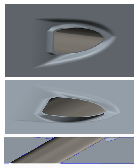
I’m an engine guy, to me aircrafts are just the things around the engines (at least the good ones with piston engines…). I'm thinking about how to install “my” engine in a typical SEP, that’s why I think about ducts and cooling systems. If I had the resources, I would like develop one, but without a wind channel and proper CFD it makes little sense. I did make a draft during my lunch break, but I’m not convinced of it. The NACA intake duct is a beautiful simple and efficient design, it would be nice to find something as good for the outlet flow.
Attachments
- Joined
- 11 March 2012
- Messages
- 3,016
- Reaction score
- 2,688
His inverted NACA ducts did not work because he installed them backwards.Been there, done that: http://www.n56ml.com/nacaducts/ - read last paragraph.
To work properly, he should have tried installing them on the inside of the cowling with the narrow, pointy end forward. Then finish with the wide, flat portion at the trailing edge. That will generate small vortexes to suck air into the duct while the wide, flat rear portion lowers air pressure to continue drawing air out of the duct. A wide, flat trailing edge exit will also expel a thin layer of hot air parallel to the nacelle boundary layer air flow.
Some scientists have speculated that heated boundary layer air flow can be used to steer airplanes. They predict that the next generation of stealthy military airplanes will have no moveable control surfaces, just ionized boundary layers or heated boundary layers to pull the tail sideways for steering. Try to picture one side of a trailing edge "lifting" more than the other. But that is a few decades in the future for amateur builders.
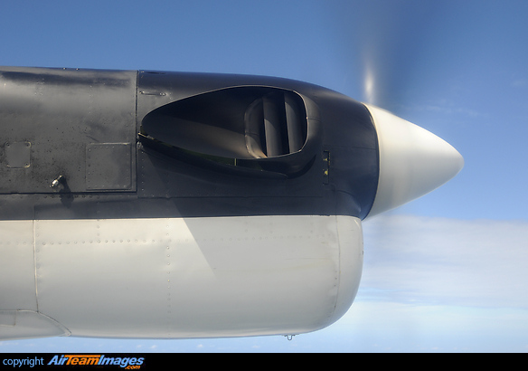
I think, almost any reasonable duct can create suction pressure, but not all can keep the exhausting air away from the surface. Here I found an example which will do this:
 www.airteamimages.com
The intentintion of keeping the air away from the nacelle is clearly visible. I guess, in this case it is mainly done for not damaging the surface with hot exhaust gases and not so much for aerodynamic reasons, but who knows...
de Havilland Canada Twin Otter Airfast Indonesia PK-OCJ
Pratt & Whitney Canada PT6A-27 engine. This is a 680 hp (510 kW) engine that was flat-rated to 620 hp (460 kW) for use in the Series 300 Twin Otter.
www.airteamimages.com
The intentintion of keeping the air away from the nacelle is clearly visible. I guess, in this case it is mainly done for not damaging the surface with hot exhaust gases and not so much for aerodynamic reasons, but who knows...