
You are using an out of date browser. It may not display this or other websites correctly.
You should upgrade or use an alternative browser.
You should upgrade or use an alternative browser.
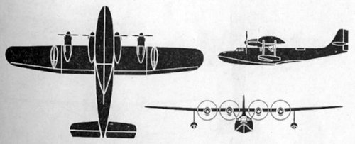
Yokosuka 12-Shi Special Flying Boat (H7Y)
- Thread starter windswords
- Start date
- Joined
- 11 March 2006
- Messages
- 8,625
- Reaction score
- 3,806
blackkite said:What is this?
http://vk.com/wall-18125720_5788
This site principally mentions, what already is said in this thread, additionally mentioning,
that flight tests weren't succesful, with the H7Y proving to be very fragile, with the wing
heavily bending during take-off (but no mention of the source unfortunately).
The side-view you've posted here, seem to show a wing with quite a low chord, so probably
implying a lond span. Taking into account a light to very light construction, certainly necessary
to achieve tghe very ambitioned performance, this could easily explain those problems.
- Joined
- 11 March 2006
- Messages
- 8,625
- Reaction score
- 3,806
The article from the link given by blackkite gives range of 9,250 km with
a bomb load of 1,600 kg, which would really have been remarkable. The
Do 26 was originally designed fro a range of 9,000 km and a payload of
just 900 kg, but with double the installed power.
a bomb load of 1,600 kg, which would really have been remarkable. The
Do 26 was originally designed fro a range of 9,000 km and a payload of
just 900 kg, but with double the installed power.
windswords
ACCESS: Secret
- Joined
- 19 May 2009
- Messages
- 389
- Reaction score
- 218
blackkite said:What is this?
http://vk.com/wall-18125720_5788
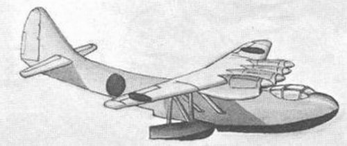
According to this site (it is in the Russian language) the H7Y1 was the classic 4 engined flying boat while the Hiro H-97 was the twin nacelle layout like the Do-26:
From Google Translate:
There is a true belief that is still within specification 12-Shi were two projects - Yokosuka H7Y, CONSTRUCT scheme classical four-layout a la LeO H-246 and project Hiro H-97, existed only on paper - in layout German repeating Do -26 ...
----------------------
So according to this site I was wrong in my previous post about which was the classic 4 nacelle and which was the 2 nacelle layout.
Winston
ACCESS: Confidential
- Joined
- 29 December 2010
- Messages
- 127
- Reaction score
- 34
It does say most importantly "Then begins the real mystery. The fact that our time has not reached any photos or explanatory drawing of the project. Referring to the authoritative sources: According to "Encyclopedia of Japanese Aircraft 1900-1945, Vol. II Aichi / Kugisho aircraft" (Shuppan-Kyodo Publishers [Japan], 1966), the project of a flying boat H7Y was so secretive that no one outside of this project does not knew about it, this is due to the lack of pictures and diagrams. There's also mention of the use of a flying boat diesel engines Junkers Jumo-205C, a few pieces of which was purchased in Germany in the late 30s. Japanese also carefully studied the German experience in the creation of a similar aircraft - flying boat Dornier Do-26. There's also the second volume Encyclopedia alleging four-circuit H7Y, in which the German Jumo-205C engines were installed on the Japanese boat in pairs in tandem, rather reminding scheme Dornier Do-26. Renowned aviation historian Tadashi Nozawa at the same time that the Japanese project was a twin-engine scheme, the truth seems unlikely for the machine take-off weight of 18 tons."
I am not sure what sources these books and Nozawa are referencing but now it seems like only speculation. The real answer is probably lost to time.
I am not sure what sources these books and Nozawa are referencing but now it seems like only speculation. The real answer is probably lost to time.
- Joined
- 11 March 2006
- Messages
- 8,625
- Reaction score
- 3,806
That's the problem with those automatic translations, I think. Another part can be read
approximately as "... this could explain differences between several sources, according to
this project, which sometimes is credited to Hiro (H-97) and sometimes to Yokosuka (H7Y).
Those two state owned arsenals were split in the 1920s and re-united during the late 1930s,
at leat with regards to design work on this aircraft. So maybe both could be the same project."
That's an attempt to clean up the Google translation only, but it could mean, that we are
looking at different layouts of the same project and not at two contenders.
- Joined
- 11 March 2006
- Messages
- 8,625
- Reaction score
- 3,806
blackkite said:... I want to see front view, especially parasol wing support structure.
Sorry, no front view, but I wouldn't expect many surprises by it either .
") Judging the drawing,
Judging the drawing,it's very similar to that of the PBY Catalina. It seems to be positioned exactly on the centerline. What's
more strange, I think, is the lack of supporting struts.
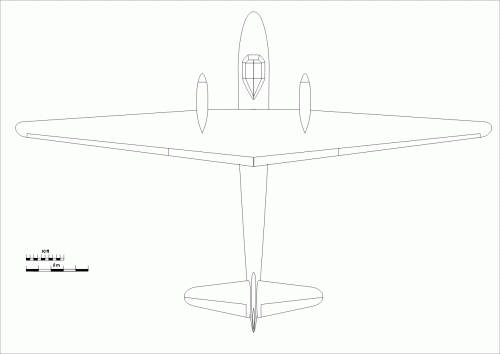
Based on this drawing and others of the Do 26, I tried to reconstruct a simplified plan view, with the engine
nacelles as main point of comparison. For achieving long range, I thought that a high aspect ration may
have been chosen, something like the Davis wing, which was offered to Consolidated at the same time,
this project started. So I used the length/span ratio of the Consolidated XP4Y Corregidor. Not to be
mnisunderstood, I don't want to say, that maybe Japan had got information about the Davis wing via
espionage, or treachery .... just, that similar problems may have resulted in similar solutions.
Starting from the side view directly and a trapezoidal wing shape, I stumbled across the point, that he shown
position of the engines would be much too far outboard ! So I chose a straight leading edge for the center
wing, but this could indicate, that the side view isn't fully correct. Another slight problem were the engine
nacelles, as the props seem to have much bigger spinners, than those of the Do 26.
So highly speculative and only intended as a thougt-provoking impulse !
Attachments
- Joined
- 11 March 2006
- Messages
- 8,625
- Reaction score
- 3,806
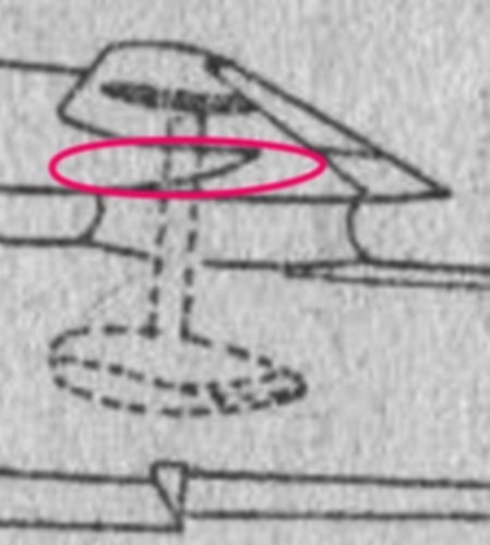
blackkite said:... But you forgot wing tip float.
Nope ! As they are drawn in dotted lines and as a wing, as clean as possible probably was
mandatory for achieving aerodynamic cleanness (and so the range goal), they certainly
were retractable. Optimum would have been to retract them into the engine nacelle, or
at least into a recess in the wing, where they would protruded from the underside as little
as possible. And from the upper side, they probably won't be visible then. That's at least my
interpretation. For a float forming the wing tip, as in the PBY, the wing tip would have to be
more squared, I think.
Attachments
- Joined
- 11 March 2006
- Messages
- 8,625
- Reaction score
- 3,806
Well, this could explain the difficulties I had, when I tried to match the engine
nacelles of the H7Y with those of the Do 26. I assumed, that both would have
been built with the least possible frontal area and fitting as tightly as possible.
And as power, rpm and torque was the same, I think, the choice of a prop
would have been somewhat determined. But as mentioned before, the nacelles
doesn't really fit ....
:-\
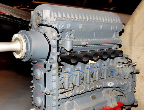
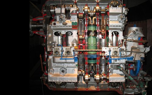
Looking at pictures of the Jumo 205, which has an unusual configuration with two crankshafts and vertically opposed pistons, isn't it possible that this powerplant was described by witnesses (remember that all written documents were supposedly destroyed) as "two engines combined in a single unit" ?
This might explain why the aircraft, with its two Jumo 205, was alternatively described as four-engined or two-engined.
Different attempt at translating the same sentence: "The main wing was a high monoplane wing, and above it were Junkers Jumo Diesel engines imported from Germany, with four engines grouped in sets of two, giving a twin-engine shape."
This might explain why the aircraft, with its two Jumo 205, was alternatively described as four-engined or two-engined.
Hikoki1946 said:"主翼は高翼単葉とし翼上にドイツから輸入したユンカース・ユモ・デーゼルエンジン4基を2基一組として双発形式とした。" "Was in the form as a set of two twin-engined Junkers-4 group Yumo-Dezeru engine imported from Germany on the wing and wing high-wing monoplane."
Different attempt at translating the same sentence: "The main wing was a high monoplane wing, and above it were Junkers Jumo Diesel engines imported from Germany, with four engines grouped in sets of two, giving a twin-engine shape."
blackkite
Don't laugh, don't cry, don't even curse, but.....
- Joined
- 31 May 2007
- Messages
- 8,819
- Reaction score
- 7,718
Today I get Japanese aeronautical academicscientific history(日本航空学術史). This book is a reliable book, becuase this book was made based on designer's memory.
The explanation about H7Y1 (特殊偵察機, special reconnaissance aircraft) is as follows.


The explanation about H7Y1 (特殊偵察機, special reconnaissance aircraft) is as follows.


blackkite
Don't laugh, don't cry, don't even curse, but.....
- Joined
- 31 May 2007
- Messages
- 8,819
- Reaction score
- 7,718
H7Y1 shape is same as Ed-san's contribution.
Abstruct of H7Y1 specification is as follows.
Chief designer : Yukio Ootsuki, MIT graduates in 1927, Kugisho member
Project period : 1937/7-1939/7
Objective of H7Y1 : Pearl Harbor reconnaissance
Range : 5,000n.m, Speed : 140kt
Engine : Jumo601 diesel engine×4 (Jumo601 is apparently memory mistake). Perhaps Jumo205 is correct.
Gross weight : 18ton, Span : 35m
Middle wing : constant chord, Outer wing : 1/25 tapered with electrically retractable wing tip float, Wing strut : one
Fuel tank : fuselage integral type
At first directional inherent stability was negative, later this corrected by vertical tail stabilizer area increase.(後に増積)
Engine weight per one engine was 70kg heavier than catalogue data.
After modification, empty weight increased 600kg(including engine overweight 280kg).
The fuselage shape was made as a body of rotation of Kugisho No.2012 airfoil, and attached planning bottom.
Last edited:

windswords
ACCESS: Secret
- Joined
- 19 May 2009
- Messages
- 389
- Reaction score
- 218
Great work Blackkite!
Wow, this thread is a "blast from the past"; I had just joined Secret Projects and this was my first topic post.
Wow, this thread is a "blast from the past"; I had just joined Secret Projects and this was my first topic post.
Yashikor
ACCESS: Restricted
- Joined
- 22 February 2020
- Messages
- 1
- Reaction score
- 2
Jun Okamura Technology commander was the chief of H7Y.
He have published "An Whole story of aviation technology" (original text "航空技術の全貌") in 1976.
The third chapter of the part second is the title "from 12-shi to Baika"
"12-shi" is H7Y. I don't know if there is a description of H7Y...
He have published "An Whole story of aviation technology" (original text "航空技術の全貌") in 1976.
The third chapter of the part second is the title "from 12-shi to Baika"
"12-shi" is H7Y. I don't know if there is a description of H7Y...
blackkite
Don't laugh, don't cry, don't even curse, but.....
- Joined
- 31 May 2007
- Messages
- 8,819
- Reaction score
- 7,718
blackkite
Don't laugh, don't cry, don't even curse, but.....
- Joined
- 31 May 2007
- Messages
- 8,819
- Reaction score
- 7,718
Hi! From "An Whole story of aviation technology"
Outline of special flying boat (H7Y1) plan
1. In 1937, a prototype was launched at the Imperial Japanese Navy's Aviation Technology Arsenal.
2. The development objective was a non-landing round-trip reconnaissance flight between Japan and Hawaii.
3. The required specification was only 5,000 nautical miles range.
4. During the planning stage of the development of this flying boat, communication within the Imperial Japanese Navy was insufficient. Therefore, at the stage of the completion examination, the soldiers pointed out that this flying boat was not worthy as a soldier because it was weakly armed, could not strike, and had a low speed.
5. The flying boat had some technical failures, and even in the experimental phase, the Japanese Imperial Navy was not keen to develop it. Finally, the flying boat was buried from darkness to darkness
Specifications of special flying boats
1. There were four crew members.
2. The weight was 18 tons.
3. The main wing is a monoplane high-wing type of half-piece holding type, the strut was one.
4. Four Junkers Jumo diesel engines were installed on the main wing.
5. A retractable float was installed on the wingtip.
6. The aspect ratio of the main wing was very large.
7. The fuselage was very fine and delicate shape, based on the rotating body of the wing cross section,
8. The flying boat was designed according to the first-class strength standards applied to large flying boats and large attack aircraft. The standard load multiple scans were 2 to 3, the standard descent angle was 10 to 20 degrees, allowed only loose turning and loose causes.
Special flying boat test results
1. Due to the structural design of the flying boat and the design of the fittings, the rigidity was generally inadequate, and the yaw of the wing, torsion of the fuselage tail and tail, and vibration of the cockpit were particularly noticeable during running on the water. Attempting to lower the natural frequency to avoid resonance with the vibration source was the cause of insufficient rigidity.
2. During flight, direction stability was negative.
3. Due to the characteristics of the diesel engine, the lift-off power was not large compared with normal engine, and take off was difficult.
Last edited:
Similar threads
-

-
 Yokosuka (Yokosho/Yosho, Kugisho/Kusho) related topics on this forum
- Started by Stargazer
- Replies: 0
-
 Kawanishi H3K ("Belle") Long-range Recce Flying Boat
- Started by blackkite
- Replies: 2
-
-