zebedee
ACCESS: Secret
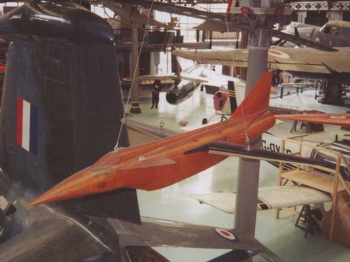
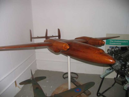
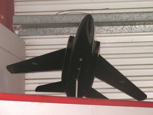
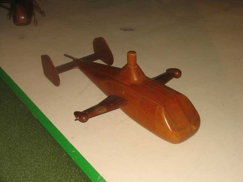
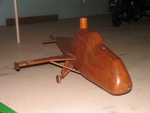
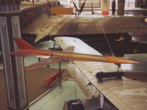
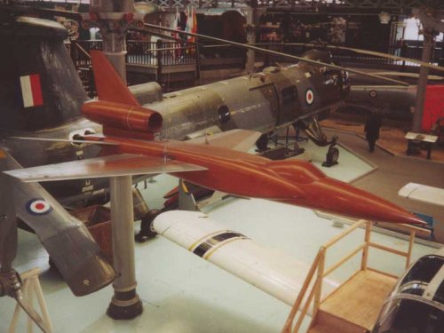
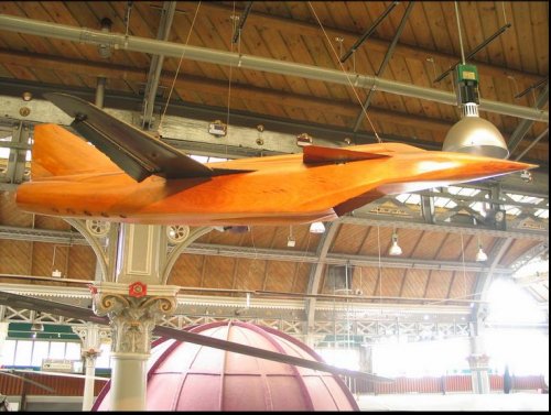
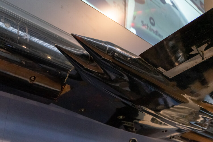
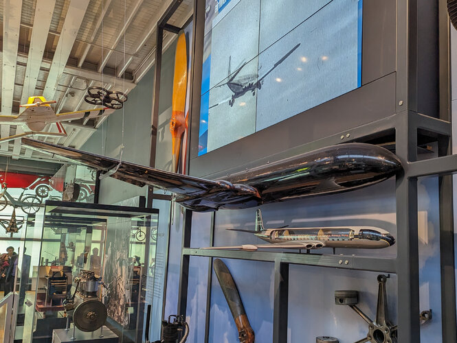
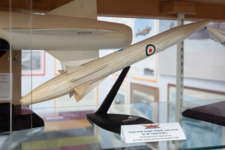
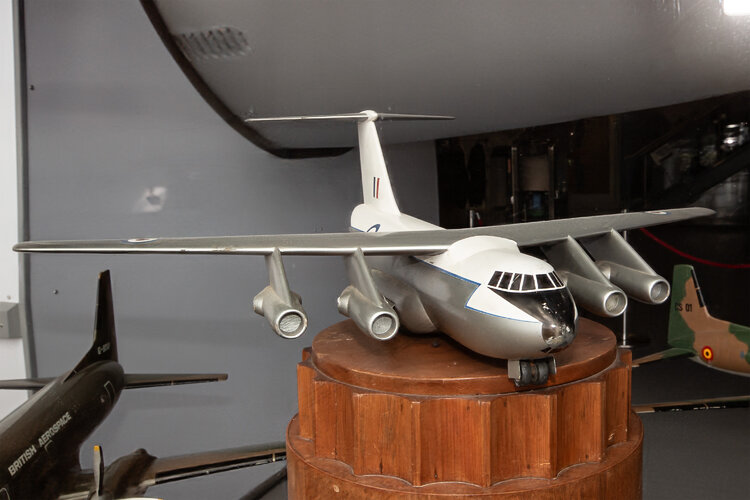
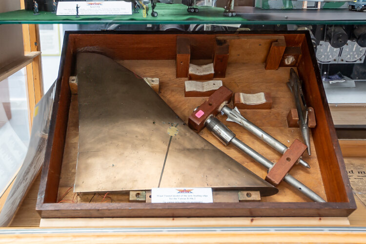
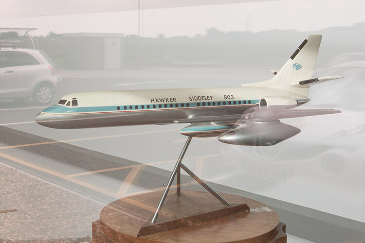
I've always had a bit of a thing about those gorgeous wooden wind tunnel models that manufacturers used to build...
Unfortunatly museums tend to squirrel them away out of sight, which I've always thought is a great pity... Anyway these are a few from Manchester and Southhampton museums which i've managed to take over the years.. I've a few more which i'll post soon.. just need to get permission first...")
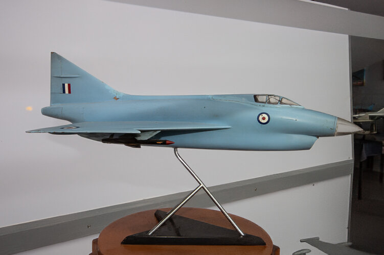
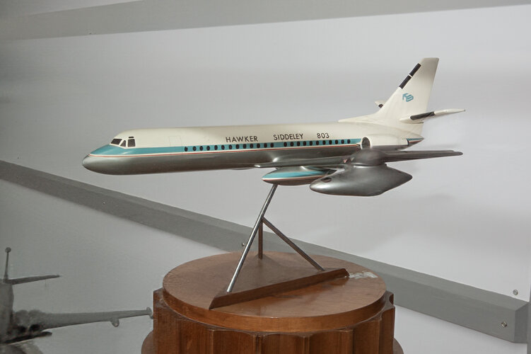
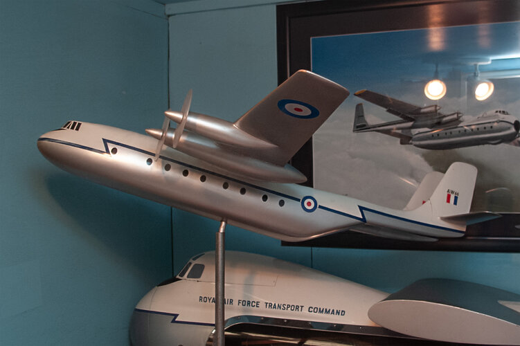
The first five i have no idea what projects they represent, the last two im pretty sure are a Gnat Mk5 and the Theseus Ambassador...
Zeb
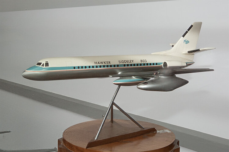
Unfortunatly museums tend to squirrel them away out of sight, which I've always thought is a great pity... Anyway these are a few from Manchester and Southhampton museums which i've managed to take over the years.. I've a few more which i'll post soon.. just need to get permission first...
The first five i have no idea what projects they represent, the last two im pretty sure are a Gnat Mk5 and the Theseus Ambassador...
Zeb