Weick W-1 and W-1A: first safety plane and forerunner of the "Ercoupe"

Steve Pace

Aviation History Writer
Joined
6 January 2013
Messages
2,266
Reaction score
225
Here's the Weick W-1A (NASA Langley).
 

Attachments

  • Weick W-1A EL-2003-00271[1].jpg
    Weick W-1A EL-2003-00271[1].jpg
    665 KB · Views: 354
[NOTE: this aircraft had been posted in the "Flying Cars" topic, but since it wasn't quite appropriate I elected to split the post out and start a new thread instead.]


Here is an account of the Weick W-1 and W-1A in the words of M. C. "Kelly" Viets of the Stilwell, Kansas-based Ercoupe Club, who knew Fred Weick personally and had access to his early documents and data. This was published in The Vintage Airplane Vol. 1, No. 2 (January 1973) and has been slightly adapted for publication here:

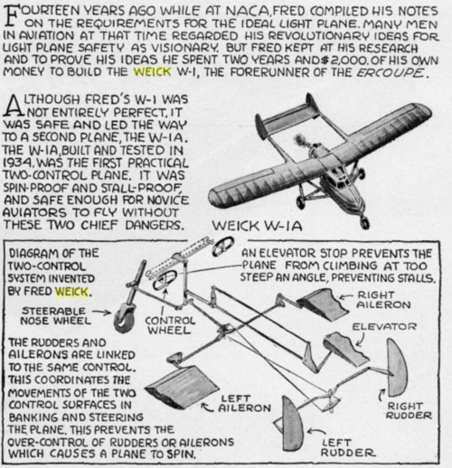
Fred Weick was a very methodical and practical man while being blessed with true genius as few men are. In 1930, Mr. Weick set down a list of 25 things which he considered were necessary for the criteria of the ideal light plane design. His preliminary statement of light plane requirements, a one-page memorandum, which was born of discussion with countless pilots, engineers, etc., as well as his own experience, called for a plane with the following characteristics (besides linked controls and freedom from spin and wing-tip stall):
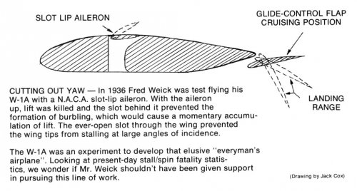
  • Ability to land safely at both the greatest angle of attack and the greatest gliding angle maintainable in other words;
  • ability to make satisfactory landings without particular respect to the pilot's skill;
  • stable "hands off' level flight, i.e., level flight without constant, wearisome fussing by the pilot, as was the case with an old, unstable plane like the Jenny;
  • dynamic longitudinal stability as nearly as possible "dead beat", that is, if the nose is raised or depressed, as by a gust, the plane should return to level flight without excessive up-and-down swaying or "hunting";
  • inability to maintain a dive at a speed greater than 1.1 times the maximum horizontal speed;
  • wide range of vision in the air and on the ground; reasonable comfort in gusty and bumpy air;
  • minimum air speed, 30 mph; cruising speed 100 mph;
  • take-off run 100 feet; landing run 50 feet;
  • rate of climb 400 feet a minute;
  • optimum angle of climb about 10 degrees;
  • minimum gliding angle, five degrees or less; maximum gliding angle, 27 degrees;
  • simple engine and auxiliary controls;
  • simple, rugged structure, to keep down repair time and original and maintenance cost;
  • vibration, only slight and unobjectionable;
  • side-by-side seating, to permit companionship;
  • interior quiet enough for normal conversation;
  • built-in crash protection for pilot and passenger;
  • and the plane as a whole small in size.
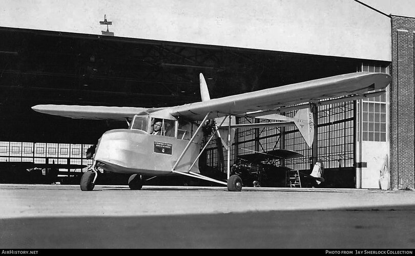
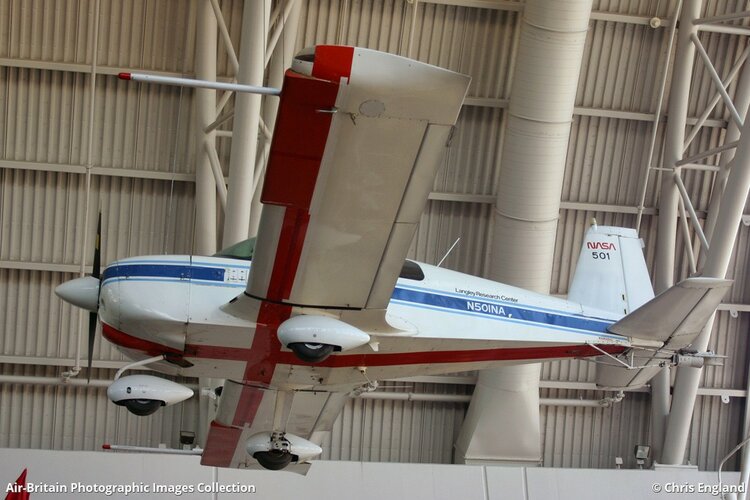
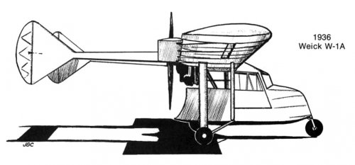
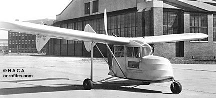
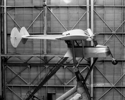
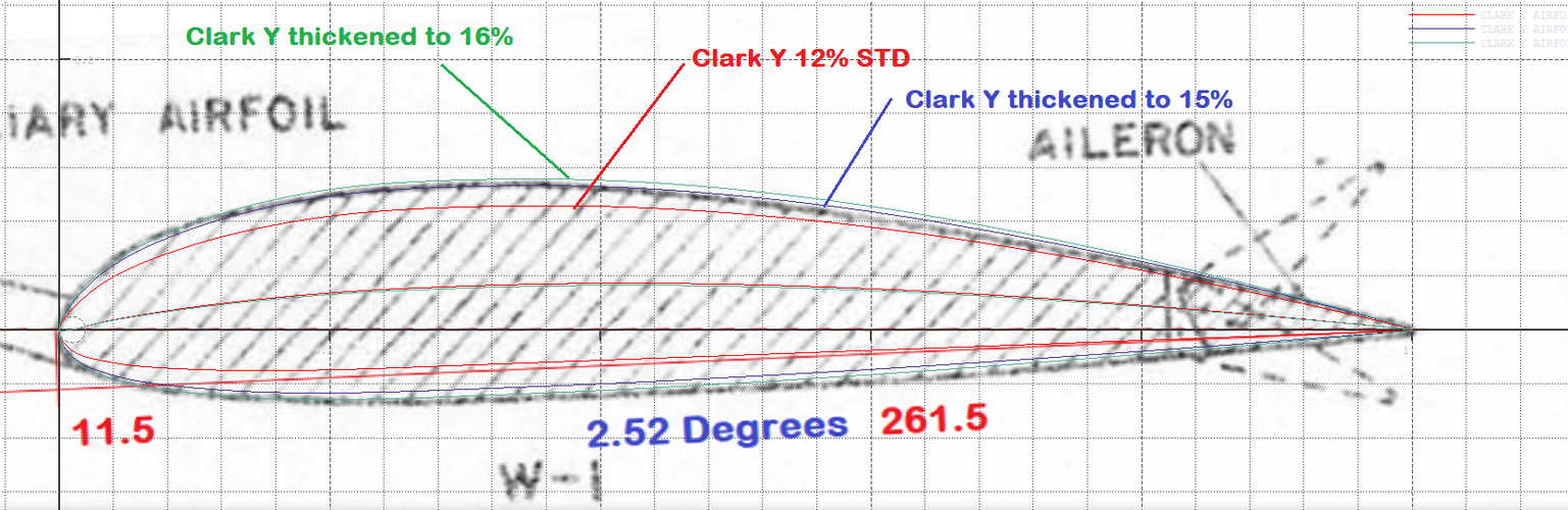
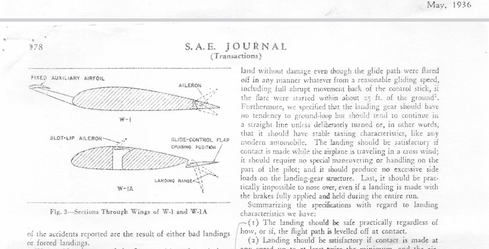
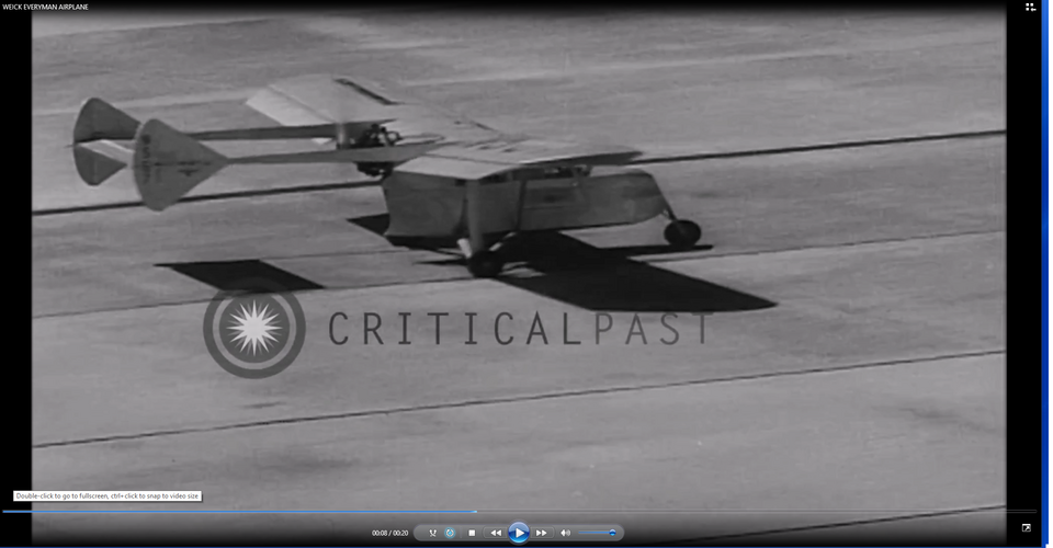
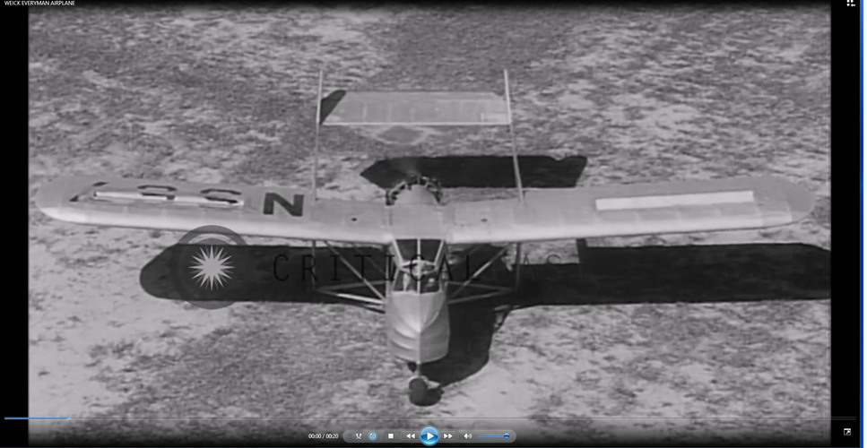
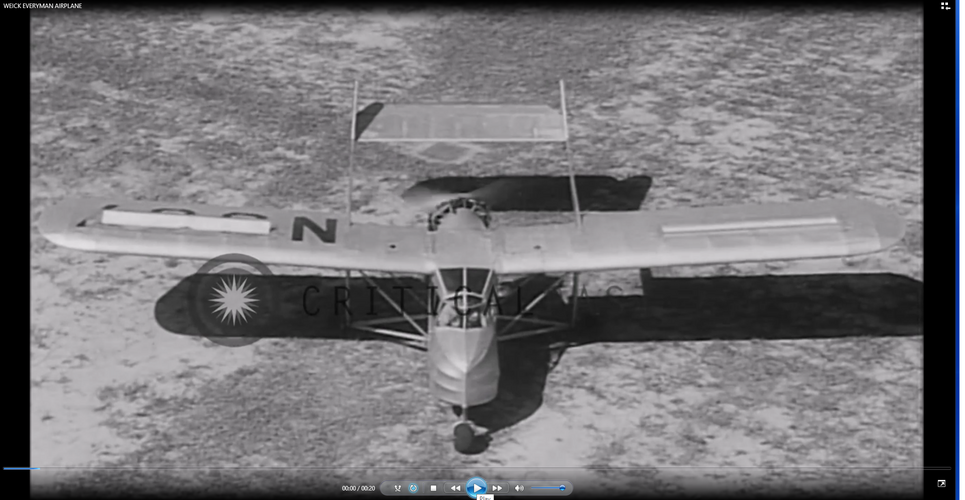
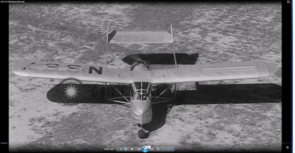
Then during the winter of 1933-34 he, along with some friends, constructed his first aircraft which embodied his criteria. The aircraft was a high wing monoplane (unique in 1934) with a pusher engine, twin booms to twin rudders, the main wheels were widely spaced at the rear and .. . "HORRORS!" ... there was a nose wheel.

Now, this really shook up the Civil Aeronautics personnel. The plane was appropriately called W-1. The plane was built following a series of tests with gliding models -built in his basement in slightly over a year's time -the cost approximately $2,000.00. This included a geared drive Pobjoy engine. Built of wood and steel tubing it is interesting to note some of the design figures. The plane had a 30 foot span, weighed 1,150 pounds, wing area was 161 square feet but it only cruised at 80 mph. But it did accomplish its purpose. Its stalling speed was 35 mph, take-off run was 120 feet and landing run was 100 feet.

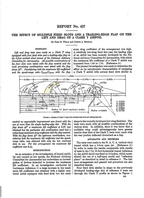
About this time the Bureau of Air Commerce, under Mr. Vidal, became interested in private flying and started a research program to produce a $700 light plane that would be safe for the average man to fly. The man they placed at the head of this project was Mr. John H. Geisse.

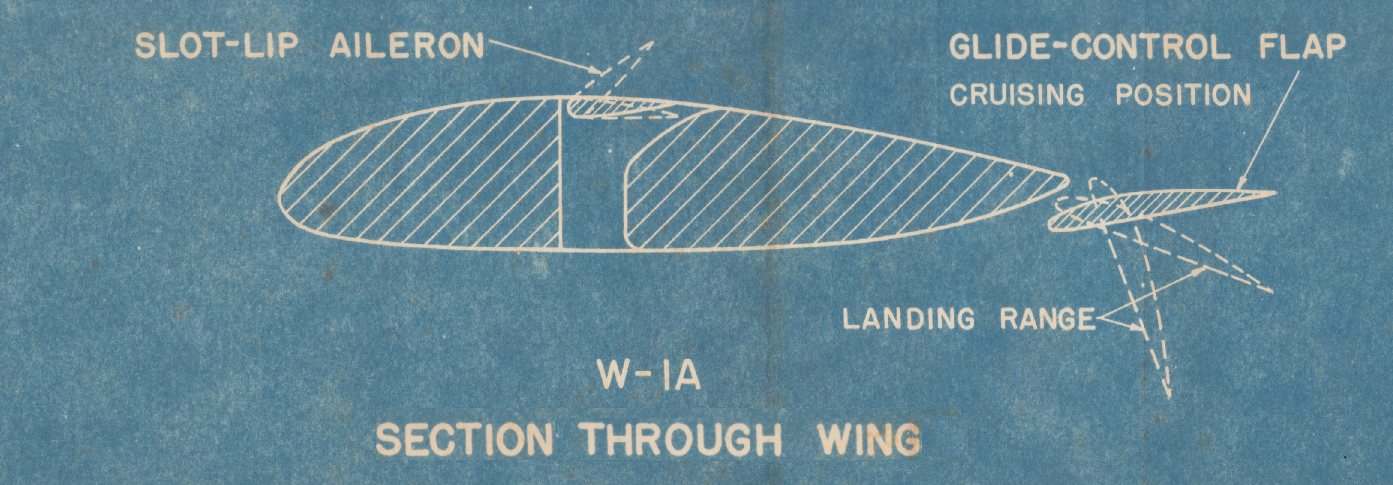
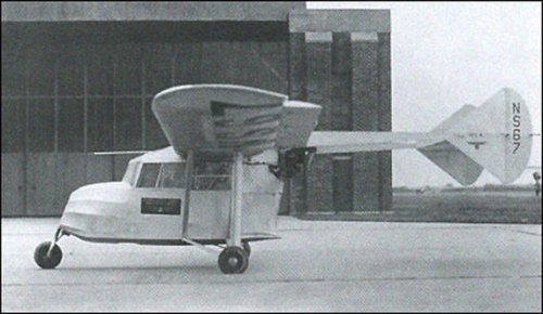
His first step was to contact the NACA. There he met aircraft which met or exceeded their proposed specifications. The Bureau arranged to purchase the plane for tests for $5,000.00. This accomplished, they immediately ran into a typical bureaucratic reaction of aversion at the purchase of a "backyard" aircraft. Therefore, they had Fairchild construct a copy so they could test a "professional" product. This plane was called 
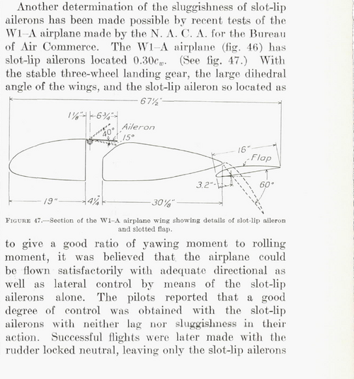
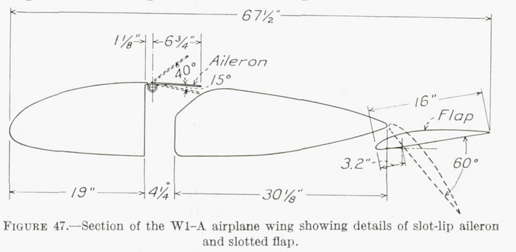
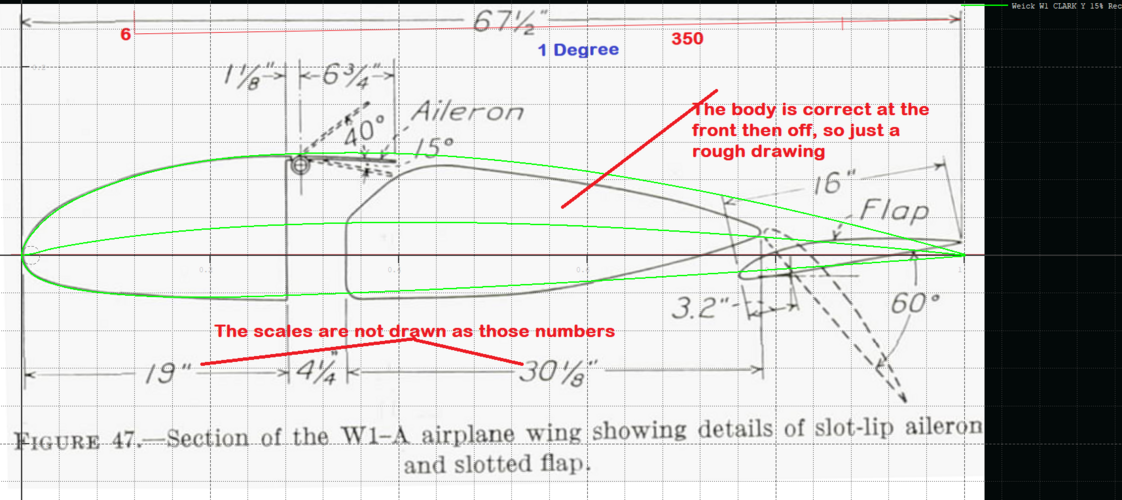
W-1-A. Similar in all respects except the plane was equipped with flaps instead of the fixed slots on the original. Again, typically, they were so sure something had to be wrong with a nose gear that they ended up destroying the aircraft trying to produce "shimmie" in the nose wheel. All this in the face of the fact that no "shimmie" problem had developed in the original design.
Mr. Weick had been in touch with an old friend, Mr. Henry Berliner, who was head of Erco, a firm of aviation tool makers. Mr. Berliner was, by the way, the son of the inventor of the microphone. From this meeting these men set out to design an aircraft which not only had all the safety principles but would have good looks, sturdiness and utility.

Thus began the story of the legendary Ercoupe, the number ONE mass production tricycle gear.
 

Attachments

  • cutting out yaw.jpg
    cutting out yaw.jpg
    101.7 KB · Views: 131
  • W-1A by Jack Cox.jpg
    W-1A by Jack Cox.jpg
    52.1 KB · Views: 173
  • weick.jpg
    weick.jpg
    22.9 KB · Views: 162
  • Weick W-1A (NS67).jpg
    Weick W-1A (NS67).jpg
    57.2 KB · Views: 170
  • Weick_W-1_-_GPN-2000-001399 small.jpg
    Weick_W-1_-_GPN-2000-001399 small.jpg
    330.8 KB · Views: 195
Last edited:
Does anyone know if there are full scale plans of the Weick W1-A , particularly of the slot lip aileron system, the specific airfoil cross-section including the "glide-flap" details . . . Jim Druffel
 
Does anyone know if there are full scale plans of the Weick W1-A , particularly of the slot lip aileron system, the specific airfoil cross-section including the "glide-flap" details . . . Jim Druffel
Type this into Google

"naca slot lip aileron"
 
In all of the Google searches of "slot lip ailerons" that I've done, I could find no detailed drawing of the slot lip aileron control assembly . . particularly, a drawing that shows how the slot "vanes" individually open and close in relation to one another. For example, when one slot vane opens, does the opposite slot vane retract into the slot opening like a standard aileron . . or does it remain stationary ?
Also I have found no detailed drawing, suitable for reproducing the Weick
W-1-A glide flap system. NACA report #547 describes the slot lip system but not the detailed mechanics of its operation.
I made the assumption that they are just activated as normal!

BUT I have been through my files and found the following two diagrams, if that helps!

The diagram in NACA TN-2404 is right at the bottom.

There is also further info in one of his patents showing cable runs(ATTACHED) it appears the Slot Lips Aileron's are interconnected by that cable across the top, implying for one to go up the other must come down!

If you find any more out about it I would be interested to know....
 

Attachments

  • WEICK FLAP AND AILERON CONTROL LINKED SYSTEM.png
    WEICK FLAP AND AILERON CONTROL LINKED SYSTEM.png
    152.1 KB · Views: 44
  • WEICK W-1A CONTROL SYSTEM 2-CONTROL EVERYMANS AIRPLANE BKP.png
    WEICK W-1A CONTROL SYSTEM 2-CONTROL EVERYMANS AIRPLANE BKP.png
    1 MB · Views: 44
  • WEICK PATENT DIAGRAM CONTROLS.png
    WEICK PATENT DIAGRAM CONTROLS.png
    97.2 KB · Views: 47
  • US2110516 weick 1938 patent showing aircraft with slot lip.pdf
    2 MB · Views: 11
Last edited:
Thanks so much for your reply and the attached documents !
The patent wording on page 5 pretty much settles the issue:
" by rotating the wheel (32) to the right and left, spoilers (36) are DIFFERENTIALLY, vertically swung to control the airplane to the right and left and . . . generate a rolling moment . . . "
SO . . . in a turn or roll , the spoiler that is not being raised must "deflect" to some degree downward into the slot cavity. . . and according to the patent language the spoilers do indeed act "differentially".
I plan on checking this out a little further with the National Air and Space Museum papers donated by Donald Weick in 2016 (47 boxes) but for now I can go ahead with preliminary design work on our slot lip aileron configuration. The attached info from NACA TN 2404 is also a big help.
Thanks again so much for helping to get our project over this "speed bump".
I'll keep you posted on anything new that I find on this subject. . . Jim D.
 
No problems happy to help.

I wonder if the up versus down linkages have a differential movement, where they go up at a greater angle rate than they move down!

In some other Weick/Naca slot lip papers there does not look to be any room for them to go down much....

This Blueprint is labeled as the W-1A and shows a little down movement, I got it from a paper a few years ago, but cannot remember which one.

As to the airfoil used I found a Weick reference to a Clark Y with an auxiliary airfoil(UP FRONT) paper of Weick's, although it doesn't look like the airfoil used on the W-1A but has the ordinates for the main airfoil and the auxiliary airfoil, in this link:


The Weick W1 supposedly had a Clark Y, according to the incomplete airfoils website, The W-1A looks different??

Also this attached Weick one on wheel and cable linkages for skewed control surfaces.

Plus this original color scan of the patent.

Also NACA TR-422 with skewed Slot lip ailerons(ATTACHED)

I assume you have seen the Everyman's airplane article, but here it is anyway..

What is the project that you building a W-1A replica?
 

Attachments

  • SLOT-LIP AILERON WEICK W1-JUNKERS TYPE BLUEPRINT - Copy (3).png
    SLOT-LIP AILERON WEICK W1-JUNKERS TYPE BLUEPRINT - Copy (3).png
    1.3 MB · Views: 28
  • 19930091518 TECH REPORT 444 SKEWED AILERONS WEICK.pdf
    1,010.5 KB · Views: 10
  • US_Patent_2110516_for_W-1_Aircraft WEICK HI RES ORIGINAL COLOUR.pdf
    8.2 MB · Views: 17
  • BEST ARTICLE WEICK Everymans_Airplane_Article JUNKERS AND SLOT LIP.pdf
    3.7 MB · Views: 12
  • naca-report-422 Wind Tunnel Research Comparing Lateral Control Devices, Particularly at High A...pdf
    1.2 MB · Views: 8
Last edited:
More on the airfoils,

This schematic shows the W1 compared to W-1A.... indicating the same source, I have compared the W1 one to a Clark Y and even fattening it it does not match a Clark Y. The Ordinates in that PDF Report number 428 will also likely not match the schematics.

So the conclusions must be those schematics are not what was built, but are just for illustration purposes.
 

Attachments

  • WEICK W-1 AIRFOIL IS NOT CLARK Y PROFILE COMPARISON.png
    WEICK W-1 AIRFOIL IS NOT CLARK Y PROFILE COMPARISON.png
    456.6 KB · Views: 23
  • WEICK W1 VERSUS W-1A Airfoils from everymans aeroplane.png
    WEICK W1 VERSUS W-1A Airfoils from everymans aeroplane.png
    845.1 KB · Views: 28
Last edited:
I have a video of the W-1A moving its controls but cannot upload it in here but you might be able to find it on the Youtube channel "critical past"

I have taken some still frames off the video to show that the Ailerons are connected and do go up and also down into the wing somewhat..

They also operate when turning whilst taxying at speed!

Enjoy...
 

Attachments

  • W-1A CONTROLS 4 TURNING WHILST MOVING.png
    W-1A CONTROLS 4 TURNING WHILST MOVING.png
    1.1 MB · Views: 29
  • W-1A CONTROLS 3.png
    W-1A CONTROLS 3.png
    1.7 MB · Views: 28
  • W-1A CONTROLS 2.png
    W-1A CONTROLS 2.png
    1.6 MB · Views: 25
  • W-1A CONTROLS 1.png
    W-1A CONTROLS 1.png
    1.6 MB · Views: 24
Adding some more value I have have recreated the W1 airfoil from report 428 and it matches the one I had previously found for a Clark-Y

Once derotated.

Buts that's still a thin 12 % airfoil, but what the report showed.

That TXT file can be renamed as a DAT file and used inside analysis software as its now in Selig format and derotated.
 

Attachments

  • WEICK W1 CLARK Y AIRFOIL RECREATION FROM NACA REPORT 428.png
    WEICK W1 CLARK Y AIRFOIL RECREATION FROM NACA REPORT 428.png
    90.1 KB · Views: 19
  • CARK Y RECREATION FROM REPORT 428-Derotated- COMPARED TO ANOTHER SOURCE.png
    CARK Y RECREATION FROM REPORT 428-Derotated- COMPARED TO ANOTHER SOURCE.png
    14.8 KB · Views: 19
  • Weick W1 CLARK Y Recreation 299 DEROTATE DEROTATE-Selig DAT FORMAT.txt
    7.6 KB · Views: 5
Now in Weick NACA TN 547 we have Slot Lip Ailerons being studied and they have clear drawings of AN AIRFOIL that is fatter than a Clark y 12%.....

They also have made a small disclosure in a diagram as to the thickness of the Clark Y they actually used!!!!!!!!!!

So we can PERHAPS assume that that is what the W-1 and W-1A started with......

It states the test wing has a 15% or 16% thick Clark Y, its not clear enough to see which.

So I found a Better copy of the report(Page attached) and its 15%

The diagram example I grabbed from the other report measures at about 14% thick so close enough.
 

Attachments

  • MEASUREMENTS OF THICKNESS OF EXAMPLES.png
    MEASUREMENTS OF THICKNESS OF EXAMPLES.png
    124.4 KB · Views: 16
  • NACA TN 547 CLARK Y 16.png
    NACA TN 547 CLARK Y 16.png
    49.9 KB · Views: 16
  • CLEARER COPY OF REPORT SHOWING 15 THICKNESS.png
    CLEARER COPY OF REPORT SHOWING 15 THICKNESS.png
    45.1 KB · Views: 17
Last edited:
So now we just compare an ACTUAL Clark 15% derived from the Weick Ordinates and as expected its a bit bigger than the drawing they have but 15% is what they intended and what they used in the tests, so maybe the aircraft as well.

That is about as close as one can get without any more evidence.....

Attached is the Selig DAT file of the Weick W1 15% Clark Y as a TXT, just change to a ".DAT" before inputting to other apps.
 

Attachments

  • Weick W1 CLARK Y 15% Recreation 299 Selig DAT format.txt
    7.6 KB · Views: 3
  • REPORT DRAWING 14% COMPARED TO A REAL CLARK Y 15 AS MENTIONED IN THE SAME REPORT WAS ACTUALLY ...png
    REPORT DRAWING 14% COMPARED TO A REAL CLARK Y 15 AS MENTIONED IN THE SAME REPORT WAS ACTUALLY ...png
    442.8 KB · Views: 17
While we are on a roll, how about those dimensions you asked for at the beginning, took a while to find...!

It even has the angles, +40 and -15 for the SLA's;)
 

Attachments

  • DIMENSIONS OF W1-A WING ETC ETC GREAT.png
    DIMENSIONS OF W1-A WING ETC ETC GREAT.png
    475.7 KB · Views: 17
  • WEICK W1-A WING DIMENSIONS  HI-RES.png
    WEICK W1-A WING DIMENSIONS HI-RES.png
    482.2 KB · Views: 18
I overlayed the 15% Clark Y but whilst it is ok at the nose it doesn't work elsewhere.

While the dimensions on that drawing are likely correct they don't scale properly on the drawing, so its likely just a rough
drawing for illustrative purposes.
 

Attachments

  • WEICK W1-A WING DIMENSIONS  HI-RES With CLARK Y 15% OVERLAYED.png
    WEICK W1-A WING DIMENSIONS HI-RES With CLARK Y 15% OVERLAYED.png
    507.2 KB · Views: 27
Wow ! what a goldmine of information ! I'll get back with you on our progress so far and a response to your research findings . . . Jim
 
Wow ! what a goldmine of information ! I'll get back with you on our progress so far and a response to your research findings . . . Jim
No probs, I enjoyed digging it all out from my files and other sources. Weick was a smart man.
 
For sure . . . the W-1A must have used differential aileron control for the slot-lip flaps as described in reports # 422 and #442 to achieve the 40 degree up and 15 degree down travel. . . so we will start with this configuration. . .and thanks for the leads on this.
Also, thanks so much for the "Everyman's Airplane" article in its entirety, previously we could only get a brief "teaser" preview of it.
Whether we use the Clark Y or some variation on it, your research will help us and is very much appreciated.
Our project involves expanding on Fred's work to develop a 4 place "utility" version of the W-1A for the new, yet unpublished FAA "MOSIAC" standard that, as we understand, will allow for a 4-place "amateur- built" / kit built aircraft with a stall speed of about 55 mph. . . that, while it may not be used "for hire", may be used for personal business purposes. We are looking at the Lycoming 0-360 180 hp pusher engine, with a very large cabin area.
We would be thrilled if this thing would cruise at about 120 mph and anything over that would be a bonus. A 600 -750 fpm Rate of climb would be just fine.
We originally intended this little ship to be a "flying Volkswagen bus" with the ability of passengers to get up and easily change pilots in-flight . . and even use an aircraft type toilet in a private enclosure at the rear of the cabin.
So far we have a 1" = 1' model in progress to study design configurations, weight and balance issues, thrust line and longitudinal dihedral angle issues etc. We are NOT looking at an anorexic looking speed machine, but rather a high utility ship with an emphasis on crashworthiness an flexibility of uses.
The next step will be to produce a larger scale flying model as a test bed for various modifications.
On a final note . . .take a look a NACA report # 602, it seems to be an expansion of report #547 and includes a section on a Fairchild F-22 modified to use slot lip ailerons and compares it with the Weick W-1A.
And on a final- final note . . . where did you come up with the schematic diagram of the Weick "flap and aileron control" shown as Figure 43 in your attachment ? did I miss something, or is there a NACA report on this ?
Thanks again . . .Jim
 
The Weick W-1A as presented in French aeronautical press (L'Aérophile, Décember 1936):

1732112880143.png
 
Our main door will be about 32 inches wide by 5'-2" tall and allow entrance behind the pilot/copilot seats into the central aisleway running between the two passenger seats/pilot seats and back to a small rear compartment . . . no clambering required. We plan to carry on with Fred W's concerns with the pilots overall visibility and the comfort/safety of everyone on board.
Our fuselage as planned is 5 feet wide and looks a bit like a Bernelli lifting fuselage design . . . It's boxy looking but cute.

Thanks for the timely info on the AG-2 . . . didn't know this one existed and the youtube interview with Anthony Gomez was a real treat of a time capsule on this period in aviation. . . and especially with this type of low speed, cargo intensive, crashworthy, utilitarian aircraft that we are also pursuing. (FYI, our design may work for small scale aerial applications ).
The "slot lip" aileron at the rear of the AG-2 wing and the "aileron flap" are of particular interest and we'd like to know more about how these two features worked together.

For now, we are still looking at a the slot-lip aileron configuration of the W1-A and the attached pages from the 1932 NACA 427 report appears to have shaped Fred's thinking. While the front slot/slat has the best increase in lift coefficient, the slot closest to maximum wing thickness (shown in yellow) is the next best option and also allows better room for the slot-lip "spoilers-flaps". One thought of ours is to have this central slot run nearly the entire length of the wing and locate the slot lip spoilers near the wing tips. . . with the rest of the slot open. We'd like to know your opinion on this configuration (FYI our wingspan will be approx. 38 ft. )
Also, we are working on a novel structural system for the entire aircraft framework that would make this less problematic.

Another thing we'd like your opinion on is the NACA 64021 airfoil that was used in the AG-2 and mentioned by Anthony Gomez in the youbetube interview as being an airfoil with a "gentle stall". (We like thick airfoils and have investigated the Gottingen 535 airfoil on another project) Would the 64021 airfoil work quite as well with a flattened bottom to simplify construction ? or is the slight convex curve on the bottom a must have ?

Thanks again for all the help . . especially from a connoisseur of airfoils. Our mock-up is about 75% complete and we are turning our attention back the the main wing.
 

Attachments

  • NACA427-1.jpeg
    NACA427-1.jpeg
    944.9 KB · Views: 10
  • NACA427-3.jpeg
    NACA427-3.jpeg
    885.9 KB · Views: 12
......

Another thing we'd like your opinion on is the NACA 64021 airfoil that was used in the AG-2 and mentioned by Anthony Gomez in the youbetube interview as being an airfoil with a "gentle stall". (We like thick airfoils and have investigated the Gottingen 535 airfoil on another project) Would the 64021 airfoil work quite as well with a flattened bottom to simplify construction ? or is the slight convex curve on the bottom a must have ?

Thanks again for all the help . . especially from a connoisseur of airfoils. Our mock-up is about 75% complete and we are turning our attention back the the main wing.
The modern approach to "gentle stall" involves large radius leading edges. Thicker airfoils help. If you are aiming at agricultural applications, then I doubt if top speed is a major priority. A thick wing might drop cruise speed by a knot or two, but the lighter structural weight will help regain some of that efficiency. Go read what the late great Chris Heintz had to say about 18 percent thick wings.
Another input - to "gentle stalls" are the updates developed by NASA during the 1970s and now standard on Cirrus and Kodiak airplanes. The outer wing leading edges are extended forward and drooped downwards. This both increases the leading edge radius and reduces the angle-of-attack (relative wind). This allows outer wing panels and ailerons to continue "flying" even after wing roots are stalled.
Yes indeed big radius LE's are GOOD....

The DLE's-Drooped cuffs as well started off as fixes as Weick was looking for, for aircraft with LE/Tip stall issues.

After problems occurred the Vulcan and Victor bombers at the high end were retro fitted with them along with the Grumman AA-1 and on the Questair Venture back in the day.

Weick came up with the SLA option so that there would still be full control ability in the stall, ailerons keep working! The DLE Cusp just delays the angle where they become uncontrolable.

In combination with the external trailing flaps the SLA is even better, if the controls are properly organized.

At high speeds with the thin airfoils required, a DLE CUSP may be a safety issue requirement but Weicks alternative may be a lot better in some circumstances.

The SLA does add drag no doubt about it, due to the lower slot, more than a DLE Cusp adds drag.

But at least one current military aircraft operates with a rearward lower slot that is well forward of other rearward control surfaces!
 

Attachments

  • imgtjjtete.jpg
    imgtjjtete.jpg
    512 KB · Views: 11
  • Quest_Kodiak_100_front_right_20130608 DLE CUFF.jpg
    Quest_Kodiak_100_front_right_20130608 DLE CUFF.jpg
    328.4 KB · Views: 10
  • Velocity_ICONA5_Web DLE showing.jpg
    Velocity_ICONA5_Web DLE showing.jpg
    533.1 KB · Views: 9
  • 1328439-large N501na Grumman AA-1 NASA TEST PLANE DLE F15 style tips etc.jpg
    1328439-large N501na Grumman AA-1 NASA TEST PLANE DLE F15 style tips etc.jpg
    162.3 KB · Views: 10
  • QUESTAIR VENTURE WING CUFFS AND RAO SLOTS.png
    QUESTAIR VENTURE WING CUFFS AND RAO SLOTS.png
    1.4 MB · Views: 10
  • Ag-2 ABOVE WING SHOT OF AILERONS AND SLOT LIPS AND INBOARD FLAP PARTIAL VERY GOOD.png
    Ag-2 ABOVE WING SHOT OF AILERONS AND SLOT LIPS AND INBOARD FLAP PARTIAL VERY GOOD.png
    1.9 MB · Views: 6
Last edited:
Thanks again for the lead on Chris Heintz and his great article titled "AIRFOILS". We are still sponging up information from your other leads such as the AG-2 . . .which lead us to a search on the naca 64021 airfoil which lead us to naca 3676 which in fig. 5 shows the AG-1 with the Zenith inverted wing type horizontal stabilizer! We have also been airfoil "shopping" at the airfoiltools.com site and
found the Glenn Martin 2 airfoil to be of interest (partly for structural reasons). . . but we're still looking for something around a 15% max thickness.
FYI our wing area (at this point) is 244 sq ft. . . . and the big difference between the Weick W-1A and our 4 place version is that we will employ a short "stub-wing" below the fuselage that will contain the 2 rear landing gear and provide an attachment point for Bellanca type external lift struts (similar to the Bellanca Airbus/Aircruiser) Also, it looks like we will be using the Junkers flaps that you mentioned instead of the W1-A flap system.
 

Similar threads

Back
Top Bottom