- Joined
- 27 December 2005
- Messages
- 18,718
- Reaction score
- 33,084
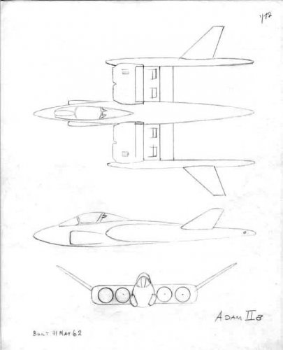
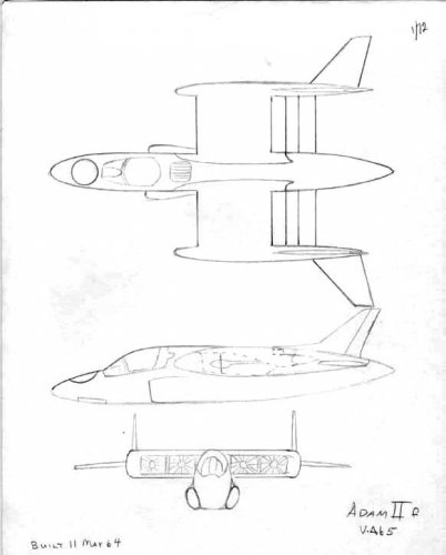
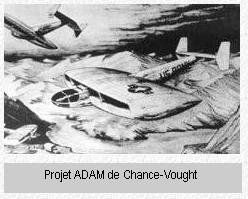
Scott has (re)posted some ADAM stuff here : http://www.aerospaceprojectsreview.com/blog/?p=100 including this VTOL ADAM fighter

Orionblamblam said:That's an ADAM design.
")
The Artist said:I believe this is an ADAM related windtunnel model. It is displayed with no information on it provided.
Bill S said:The Artist said:I believe this is an ADAM related windtunnel model. It is displayed with no information on it provided.
Nice find!
bill
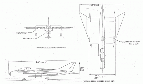
flateric said:From
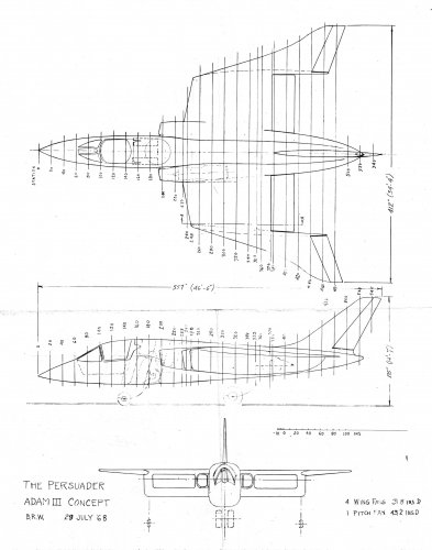
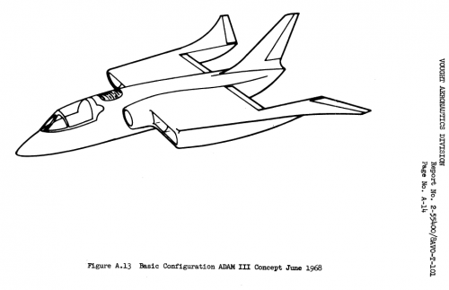
THE ADAM 111 V/STOL CONCEPT
by BYRON R. WINBORN, JR.
LTV Aerospace Corporation
Dallas, Texas
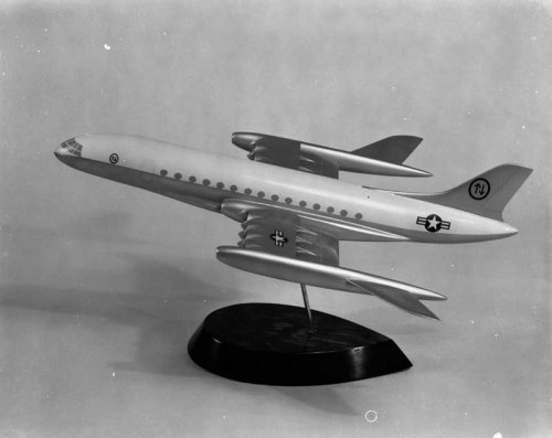
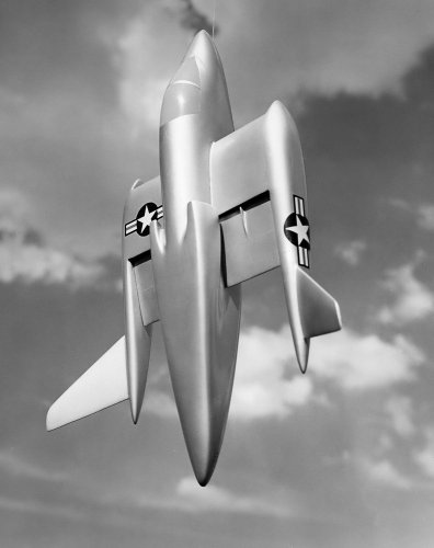
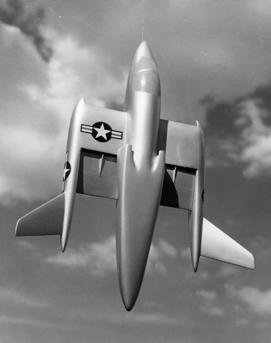
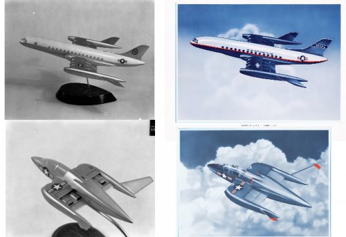
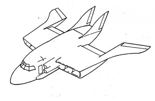
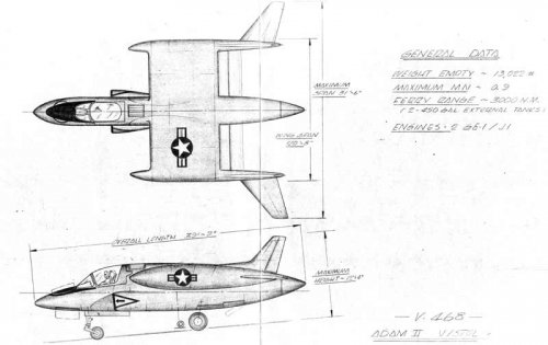
Mark Nankivil said:...and one with with a V# - V-468
Enjoy the Day! Mark
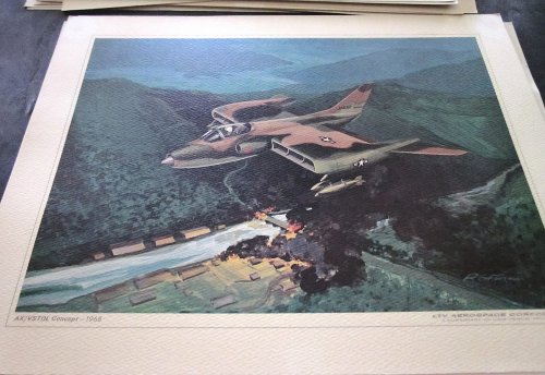
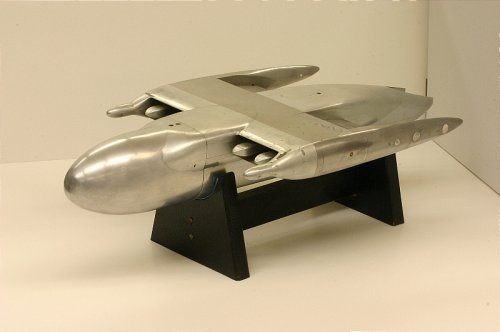
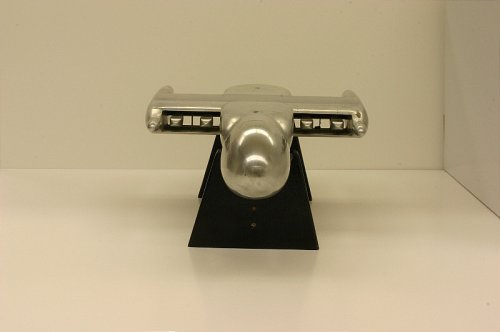
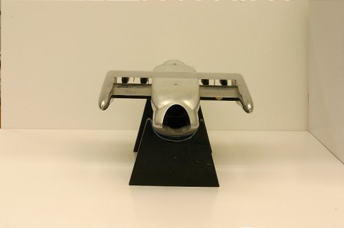
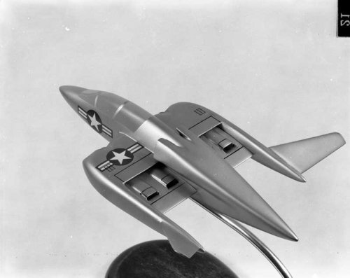
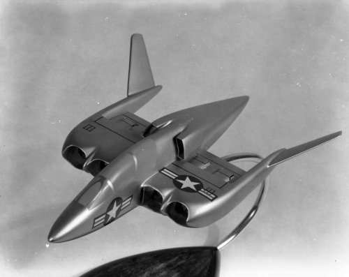
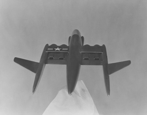
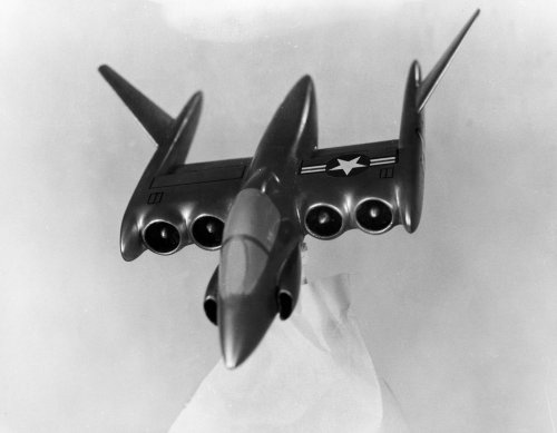
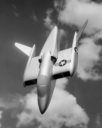
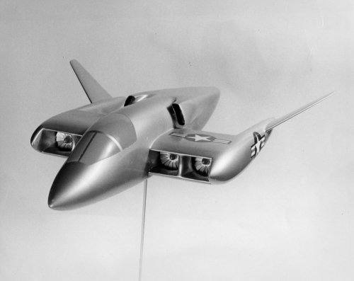
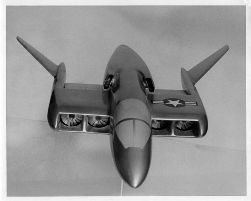
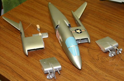
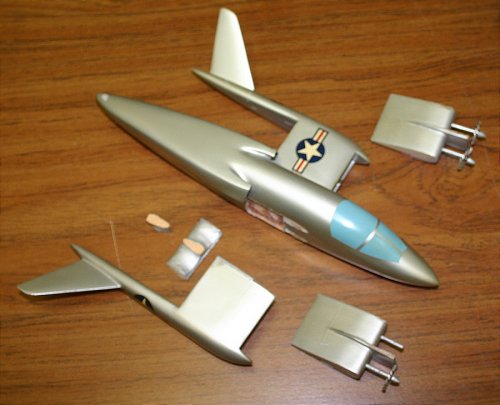
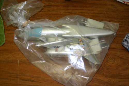
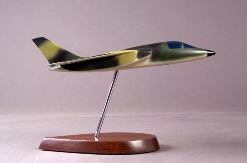
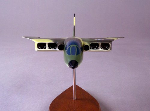
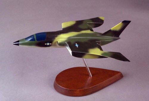
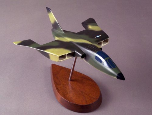
circle-5 said:Vought ADAM III "Persuader" factory model, ca. 1968. I don't know the V-model number for this one, but maybe someone does ...
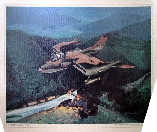
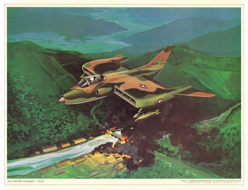
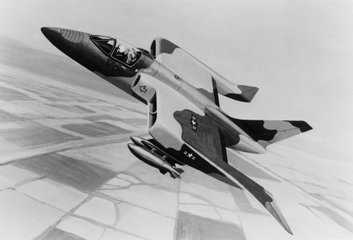
Small V/STOL Strike-Recce Airplane
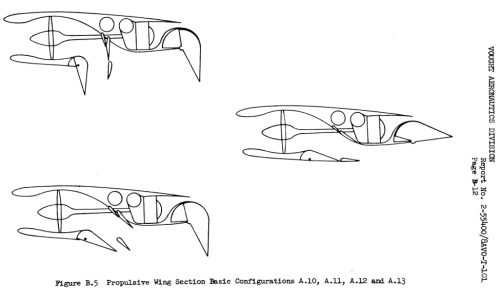
A small ADAM III high-subsonic strike-recce airplane
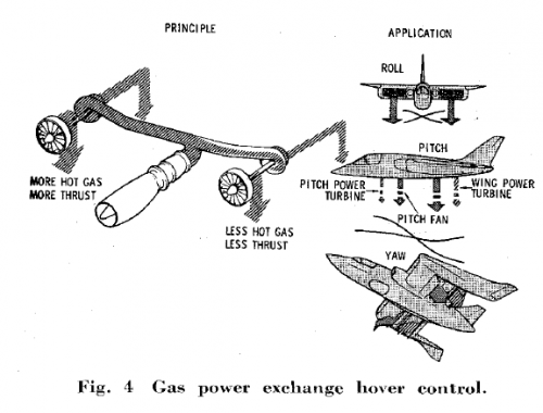
is shown in Fig. 7. The two gas generators are mounted in the
wing roots with nearly straight inlets. Two forward-facing
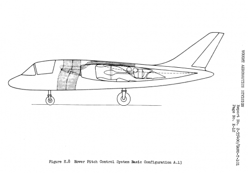
fans are installed in each wing. A large vertical axis pitch
fan is located in the fuselage immediately behind the pilot,
The efflux of the pitch fan is discharged through two rectangular
nozzles in the underside of the fuselage. The major
axes of these nozzles are in the longitudinal direction in order
to minimize suck-down effects.
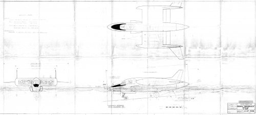
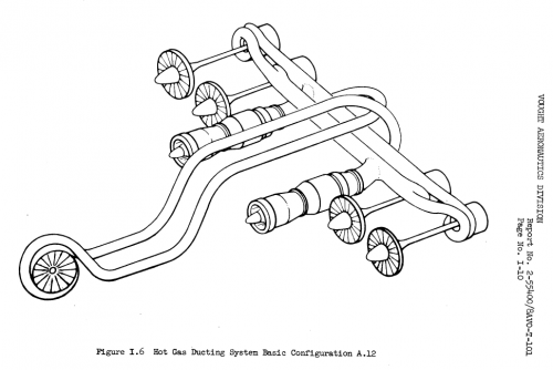
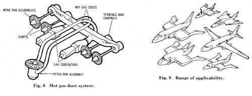
The hot gas ducting system which conveys the hot gas
from the gas generators to the power turbines is shown in
Fig. 8. Actually, two independent hot gas duct systems are
used, with each gas generator supplying hot compressed gas
to part of the periphery of each power turbine.
Each boom and outboard tail comprise an integral structure.
A trailing-edge elevon is used for flight control. Directional
stability and control are provided by a conventional vertical
tail mounted on the centerline of the fuselage. The main
landing gear is mounted under the wing, retracting into the
fairings behind the gas generators. The nose gear is conventional,
ret racting aft into the space between the two pitch
fan nozzles.
No fans, ducts, shafts, or landing gear are located forward
of the pilot's seat bulkhead. The front end of the airplane
can be configured so as to best meet user requirements. A
large amount of space is available in the fuselage forward
and aft of the center of gravity for fuel and other useful load.
Large external tanks may be carried under the outboard
boom tails. Most of the underside of the fuselage is available
for user purposes.
The VTOL downwash velocity is high enough to require
moderate site preparation. The various nozzles are arranged,
however, so that there is virtually no chance of heating the
ground appreciably. Likewise, there is no danger that hot
propulsive flows will be reingested unless the airplane is
hovered in a tail wind.
With the dual hot gas duct system, either gas generator
may be started or shut down at any time on the ground or in
flight, intentionally or otherwise, without requiring readjustment
of the other gas generator. The airplane will fly in the
cruise mode and make conventional landings with either gas
generator or either hot gas duct completely inoperative.
With loss of a gas generator or hot gas duct in the hover mode,
thrust will remain symmetrical, and the airplane will remain
controllable in a retarded descent.
All hot gas components are located aft of all wing primary
structure, so that it becomes possible to protect the primary
structure from any hot gas leak.
The transition process is continuous, and is similar to gradually
raising or deflecting the flaps in a conventional airplane.
Activation of the pitch fan is not sensitive and may be accomplished
over a wide range of flight conditions.
The useful load is approximately 43% of the VTO gross
weight under tropical day, sea level conditions. For STO
operation, the useful load may be increased to approximately
53% of the takeoff gross weight. These values are predicated
upon the use of conventional rather than exotic structural
materials.