The Development of HMS Dreadnought

Tzoli

ACCESS: Top Secret
Senior Member
Joined
1 February 2011
Messages
2,615
Reaction score
2,591
This is a copy from the Secret projects forum, regarding the development of the HMS Dreadnought with it's numerious and quite headache like preliminary designations.

My initial thread opener:

-------------------------------------------------------------------------------------------------------------------------------


I wish to understand how HMS Dreadnought evolved during her design process as well as clear what design is what
From Norman Friedman's British Battleship book:
Fisher almost immediately asked Watts to design a fast battleship with uniform armament. Watts’ instructions to his deputy J H Narbeth do not survive, but Narbeth’s 22 November 1904 answer does. There were two main alternatives, each protected like a Lord Nelson, each capable of either 20 or 21 knots. Alternative A would be armed with eight 12in in pairs. Narbeth estimated that it would require 16,000 tons and 19,000 IHP for 20 knots (about 435ft x 83ft x 27ft) or 16,500 tons and 22,000 IHP for 21 knots (about 440ft x 63ft x 27ft). The list of alternatives shows A as an eight-gun ship on Lord Nelson plan, implying two twin turrets at the ends and single 12in at the corners of the superstructure. She would displace 16,500 tons (16,000 tons with turbines) and would cost £1,360,000. DNC had previously (10 November) produced a Legend for the 20-knot version: 450ft x 79ft 6in x 27ft, 17,500 tons. The considerably greater length compared to a Lord Nelson was an important factor in higher speed, as was much greater power (in the initial Legend, 25,000 IHP vs 16,750 IHP). Continuous sea speed, the measure of strategic mobility, was to be 18.5 knots rather than 16.5 knots.
Alternative B had twelve 12in guns. Narbeth estimated that the 20-knot version would displace 18,000 tons (475ft x 83ft x 27ft, 19,000 IHP); the 21-knot version would displace 18,800 tons (495ft x 83ft x 27ft, 22,000 IHP). This was apparently Narbeth’s hexagonal turret arrangement ship proposed in 1903. It would cost £1,700,000.
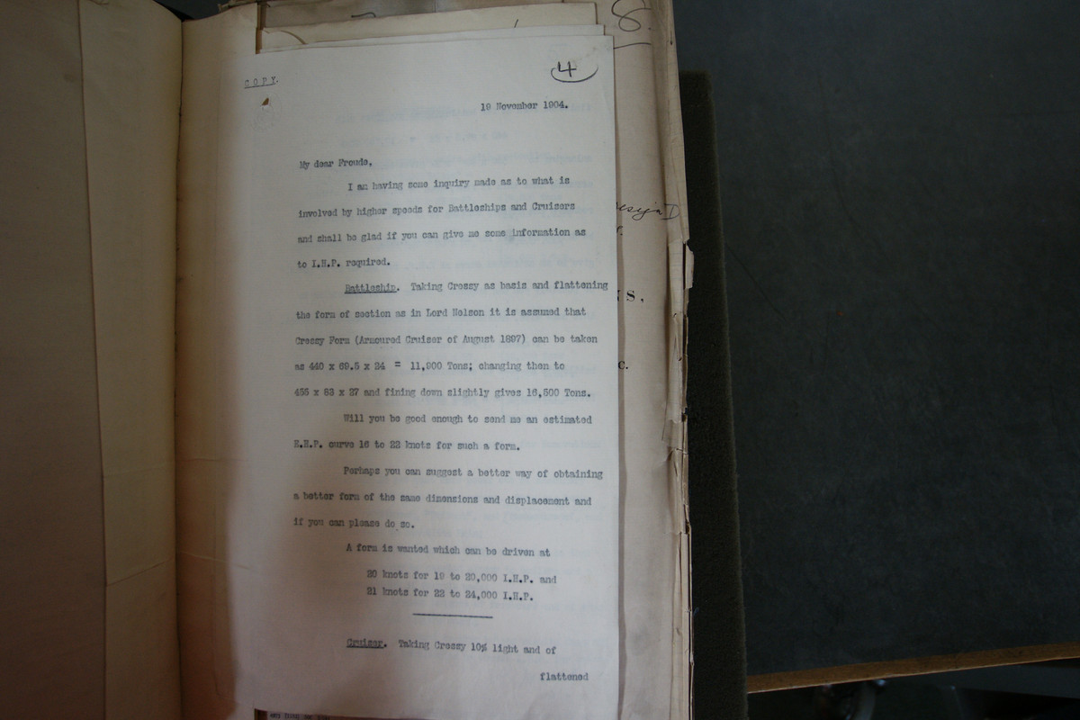
So from this the very first designs leading to Dreadnought are:
John Harper Narbeth's 1903 design with 6x2 hexagonal arranged likely 12"

DNC Design, 1904 November 10?
450(pp) x 79 x 27ft
2x2,4x1 12" (Hexagonal arrangement like Lord Nelson with single wing turrets)
17.500tons, 25.000shp, 20knots (VTE Engines?)

John Harper Narbeth's 1904 November 22 designs: ( 4x variants based on Untakeable B? )
Alternative A1 (20knots)

435(pp) x 83 x 27ft
2x2,4x1 12" (Hexagonal arrangement like Lord Nelson with single wing turrets)
16.000tons, 19.000shp (Turbine engines?)

Alternative A2 (21knots)
440(pp) x 63 x 27ft
2x2,4x1 12" (Hexagonal arrangement like Lord Nelson with single wing turrets)
16.500tons, 22.000shp (Turbine engines?)

Alternative B1 (20knots)
475(pp) x 83 x 27ft
6x2 12" (Hexagonal Nassaul like arrangement)
18.000tons, 19.000shp (Turbine engines?)

Alternative B2 (21knots)
495(pp) x 83 x 27ft
6x2 12" (Hexagonal Nassaul like arrangement)
18.800tons, 22.000shp (Turbine engines?)

Then:
Narbeth wrote that ‘a little squeezing’ and some innovations would be required. The main engines could be run harder to produce 10 per cent more power on the same weight and space (as had been achieved in the Armstrong-designed Swiftsure and Triumph and in the Admiralty-designed armoured cruiser Monmouth and considerably exceeded in the Italian Benedetto Brin); bridge and conning tower could move aft to bring the fore barbette closer to the boilers and the funnel arrangement improved; existing freeboards could be retained despite the greater length of the ship (i.e., accepting greater wetness); and a better hull form could be adopted.
Four days later Narbeth produced formal Legends for fast battleships, all armed with eight 12in, of three alternative speeds: 21 knots (A), 20 knots (B) and 19 knots (C).13 Some existing ships were rated at 19 knots. The basic designs used reciprocating engines. Substituting turbines would save considerable weight: for example, the engineering weight of A could be reduced from 2150 tons to 1700 tons. Protection could be a conventional citadel extending up to the upper deck; or citadel extending only up to the main deck, with 12in redoubts above. Watts followed up on 14 December with a Legend for a 21-knot battleship, armed with twelve 12in guns (Design D). Estimated displacement was 18,000 tons (500ft x 83ft x 27ft). D seems to have been a development of Narbeth’s earlier hexagonal turret twelve-gun design. Watts clearly favoured this arrangement as a convenient way to accommodate the ship’s vitals and also to provide space for essentials such as ships’ boats.
So the next 4 are (I don't know if this Design C had any connection to the C series of preliminary designs including Untakeable C )
John Harper Narbeth's 1904 November 26 designs:
Design A:

8x 12" (likely 4x2 or 2x2,4x1)
21knot speed, VTE engines but alternativey Turbines

Design B:
8x 12" (likely 4x2 or 2x2,4x1)
20knot speed, VTE engines but alternativey Turbines

Design C:
8x 12" (likely 4x2 or 2x2,4x1)
19knot speed, VTE engines but alternativey Turbines

Philip Watts's proposal from 1904 December 14
Design D:

500(pp) x 83 x 27ft
6x2 12" (Hexagonal Nassaul like arrangement)
18.000tons, 21knots (VTE? Turbine engines?)

Then:
Docking considerations had doomed Watts’ previous large battleship – and this one was considerably larger. Throughout the Empire, seven docks could take the ship; another twelve suitable ones were building. The ship could not dock at Chatham, Devonport, Portsmouth, Birkenhead, Glasgow or at Sydney. The new First Sea Lord was more interested in superiority than in convenience. The next day Narbeth suggested a 500ft battleship armed with eight 12in guns. With 30,000 IHP such a ship would make 22.5–23 knots.
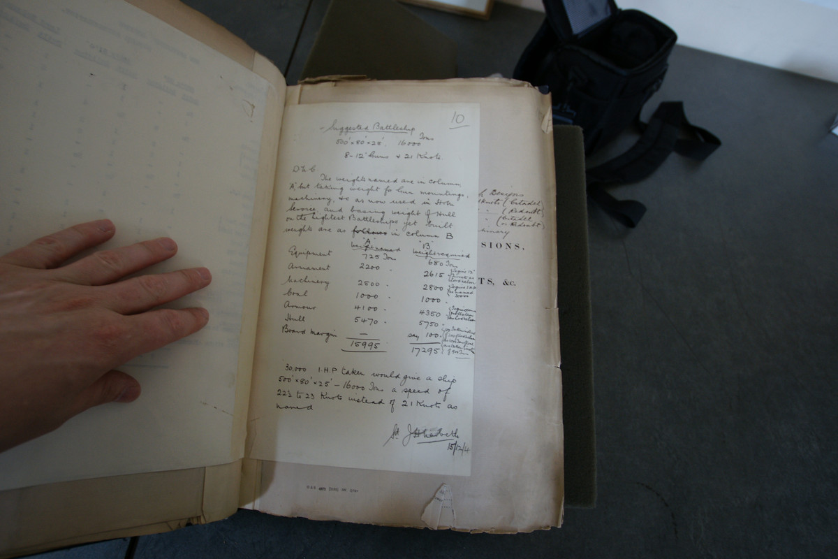
John Harper Narbeth's 1904 December 15 or November 27 design???:
500(pp) x ? x ?
8x 12" (4x2 possibly a modified Untakeable B? or 2x2,4x1 )
30.000shp, 22,5-23knots (likely Turbine engines?)

Next
On 14 December Narbeth summarised the 21-knot designs, all with turbine power (23,000 IHP in each case).14 Continuous steaming power was 16,000 IHP, nearly the full power of a Lord Nelson. That gave a continuous sea speed of 19.5 knots (19.25 knots for the larger twelve-gun ship, which was 500ft rather than 460ft long). These figures went to DNC on 21 December.
None of these designs apparently satisfied Fisher. He consulted Admiral Sir A K Wilson, the highly-regarded tactician who commanded the Channel Fleet. Wilson pointed out that every tactical exercise became a broadside-to-broadside engagement: what counted was the number of guns which could fire on the broadside. All turrets should be on the centreline. In what Narbeth called the Castle Plan, the new design had six turrets in two three-turret groups fore and aft. Each group consisted of three superfiring turrets, as in the much later Dido and Atlanta class cruisers. This design required considerably more space. A Legend for this HMS Untakeable, the name Fisher privately used for his super-battleship, was dated 21 December 1904. She was much longer (555ft x 84ft x 26ft 6in, 20,700 tons) and higher-powered (27,000 SHP for 21kts), mounting twelve 12in guns and sixteen 4in (all the earlier designs had 12pdr antitorpedo guns). Armour would have been thinner, with 10in rather than 12in at the waterline (9in upper belt) and 10in rather than 12in turret sides. This design was designated C, in a series in which A was the eight-gun ship and B Narbeth’s rather smaller twelve-gun ship.
Design D was Narbeth’s hexagonal-battery ship on roughly a Lord Nelson hull, with reciprocating machinery. It was dated 14 December 1904. For a time it seemed that this design would be chosen, so early in January Narbeth produced a variety of alternative versions.15
Design E (designated G for the Committee on Designs, see below) was yet another twelve-gun ship, arranged on what Narbeth called the Triangle Plan. Guns were mounted in and atop two triangular redoubts pointing towards amidships. A single turret was at the apex of each triangle, superfiring over two pairs of guns firing from each of the two other points of the triangle. This required a ship about as large as C. The main advantage of this configuration over Narbeth’s hexagonal ship was much greater end-on fire against a target crossing the ship’s bow, as all three pairs of 12in guns at either end of the ship could keep firing under those circumstances. This design was never fully examined by the Committee on Designs because broadside fire was far more important than end-on fire.
Design F was a cut-down version of the twelve-gun ship, with the highest forward turret and the quarterdeck omitted. That dramatically reduced topweight, so dimensions were reduced to 530ft x 82ft x 26ft (19,000 tons). Compared to the twelve-gun ‘castle’ ship, F cost £1,700,000 rather than £1,940,000. G was the least expensive all-big-gun ship, essentially half of C, with only one ‘castle’, aft. This dramatic reduction cut her to 14,000 tons (425ft x 77ft x 25ft, £1,200,000), but since G cost more than half as much as a full ‘castle ship’, her cost per gun was the highest of the lot. This was the only one of Narbeth’s designs never shown to the Committee on Designs. The lowest cost per gun was D, the Lord Nelson derivative with reciprocating engines (£1,700,000; £142,000 per gun).
So.......
I'm now confused what is Design A,B and C?
Friedman writes:
Design A was the 8-gun ship (All designs to this point by John Harper Narbeth was 8-gunned either 2x2,4x1 or 4x2 except the Alternative B designs)
Design B from my understanding is Alternative B1 with 21knots and hexagonal layout
Design C was Untakeable C either the original or the fixed design with super and super-super firing pair of turrets forward and aft
Design D was a new design based on Alternative B or B1 but VTE engines and likely enlarged Lord Nelson hull?
Design E was basically Untakeable Design 1 with larger hull and armoured redoubts / mini citadels protecting the magazines
Design F was 5x2 with 3 turrets aft and cut back aft deck / quarterdeck (530(pp) x 82 x 26ft, 19.000tons)
Design G.... Friedman description is weird, at the start he says it is Design E, but then writes it has only one "castle" at the aft eg either half Untakeable design 1 (forward part, with the aft part is the same as Untakeable C or Design C and data either for Design E or this different version G: (425(pp) x 77 x 25ft, 14.000tons)
John shared a drawing with me showing the layout of E, but labelled "Battleship G" and with this data: 550(pp) x 85 x 27ft, 21.000tons

I barely know now which design is which now.

Next:

Fisher personally opened proceedings on 3 January 1905. His reported remarks were much those he later used to justify the new type of battleship. He stated that the two governing factors in a battleship were guns and speed. All armament had to be above the upper deck (i.e., not on the ships’ sides) so that it could be fought in any weather and also so as not to interfere with net defence against torpedoes. Existing battleships had central magazines connected to turrets or other guns by horizontal passages. Fisher would reduce vulnerability to underwater attack by providing each turret with its own magazine, at a safe distance from the side of the ship (hence from any mine explosion). Bulkhead penetrations would be eliminated to improve watertight integrity, particularly against the mines which were proving so effective in the Russo-Japanese War. Since Russia and Japan had chosen 20 knots as their future standard, the Royal Navy must choose 21 knots – not as a paper speed, but as an actual speed (it might be necessary to design for 21.5 knots to be sure of making 21 knots).
The Committee was given Designs D, E and F. D was Narbeth’s hexagonal-battery ship. E was Wilson’s vertical-echelon ship (C above) with its quarterdeck omitted. F was a modified version of E with one fewer turret forward. All had Lord Nelson protection. Considerations of blast simplified the choice. Although blast had been only a limited problem in earlier battleships, whose 6in batteries were protected from 12in blast by decks and bulkheads, it now seemed that the blast from one turret could disable gunners in the sighting hood of a neighbouring one. Based on experience in several battleships, the Committee concluded that the sighting hood of a turret should be at least 63ft from the gun muzzles of the next. The naval members decided that, taking into account the length of the 12in gun and the diameter of the turret, turrets should be about 70ft apart (centre to centre). They also argued against superfiring: a lower turret would be untenable in a chase due to blast from the upper turrets. Lower turrets would be tenable only when firing within 20–30° of the beam. Wilson’s ship would offer nothing in ahead or astern fire and the concentration of turrets at each end of the ship, protected by a single redoubt, offered a very large target, the middle turret of the three being an excellent point of aim. Because Design G suffered from the same problems as the other two, it was never shown to the full Committee.
That left Narbeth’s hexagonal Design D. It carried as many guns as Wilson’s ship on 2000 tons less. A modified D1 design had the foremost turret moved up onto a forecastle, to keep it dry. A further modified D2 had the broadside turrets moved further apart, with a large boiler compartment between them. Committee members were provided with a cardboard section of the blast zone, so that they could work out the arcs of fire of the turrets on wooden models of the D designs. It was soon apparent that the close midships turrets of D1 would have very limited arcs of fire. Substituting a single centreline turret for the two after broadside turrets of the D2 design would give better performance. Blast from the two remaining broadside turrets would pass clear of the two centreline turrets aft. Blast from the two wing turrets would make it impossible to fire the forward centreline turret in a chase. On the available length, it was impossible to move the wing turrets far enough aft for their blast to clear the centreline turret forward. DNC was asked for a further design H, with the five turrets (a centreline turret replacing the two after broadside turrets and the foremost turret on a forecastle). There was no question of replacing the remaining two wing turrets with another centreline turret, because that would have taken up too much centreline space.
In the footnotes:
The variety of such versions suggests that Narbeth thought so. A list dated 12 January 1905 omits D1 and D2. D3 was 500ft x 84ft x 27ft 3in (18,500 tons), with magazines amidships and two funnels before the conning tower. D4 had magazines at the sides and partly amidships, with one funnel forward of the conning tower. D5 had engine room amidships. D6 (510ft x 83ft x 27ft) had a ten-gun broadside (configuration not clear). D7 (525ft x 83ft x 27ft, 19,000 tons) had a twelve-gun broadside and conning tower between the after guns, but boat stowage and anti-torpedo arrangement were impracticable. D8 (520ft x 83ft x 27ft, 18,800 tons) had a twelve-gun broadside and magazines at the side, but again boat stowage and anti-torpedo arrangement were impracticable. D9 (500ft x 83ft x 27ft, 18,000 tons without forecastle or 500ft x 84ft x 27ft 3in, 18,500 tons with forecastle) had a larger boiler room aft for sea steaming. The Cover lacks drawings, so it is impossible to say how Narbeth got ten and twelvegun broadsides out of evolved versions of his D design, which had an eight-gun broadside.
So... 1905 January 3 designs:
Design C
became Design E eg the triple superfiring pairs forward and aft design but with the modification of the quarterdeck reduced
Design D1, a modified Design D eg what I understand the Nassau or hexagonal layout but the forward centreline turret was risen to a forecastle as on Dreadnought
Design D2, same as D? but more widely spaced Wing turrets?
Design D3 (500(pp) x 84 x 27,25ft, 18.500tons) But I don't understand what Friedam states about the Conning Tower eg the Bridge is located BEHIND!!! both funnels!
Design D4 same as D3 but ONLY one funnel is loated in front of the Conning tower / bridge??? Also don't understand the magazine layouts he was describing. Or he describes a SECOND Conning tower???
Design D5 seems like a side by side funnel arrangment version based on the description of the engine rooms at amidships
Design D6 (510(pp) x 83 x 27ft) Unknown layout for 10gun broadside but which likely be a mix f Dreadnought and Invincible where the wing turrets at Echleon and could fire over deck
Design D7 (525(pp) x 83 x 27ft, 19.000tons) 12-gun broadside which implies 6 or more twin turrets on an unknown layout with a Conning tower (likely second?) between the aft turrets
Design D8 (520(pp) x 83 x 27ft, 18.800tons) 12-gun broadside but again I don't understand magazines at the sides???
Design D9A (500(pp) x 83 x 27ft, 18.000tons) looks like by the description is the same as Design D (Eg Design D1 without forecastle) but with larger boiler room aft?
Design D9B (500(pp) x 84 x 27,25ft, 18.500tons) Same as Design D1 but with larger boiler room aft?
Design H is basically the Dreadnought as built with the forward centreline turret on a forecastle and the rest (1-1 wing and two aft centreline turrets on the same deck level and one level lower then the first turret)

Note the missing C1-C3 and E1-E5 series

Can you guys clear my head regarding these designs???
 
The next post are John French's extensive answer clearing things up a bit and gives much more insight in the development process:
Note: I hope the images load as well.

--------------------------------------------------------------------------------------------------------------------

According to the Dreadnought’s ships cover, the following is how the Dreadnought preliminaries unfolded:

First I should mention the nearly unique circumstance that resulted in two different preliminary design branches working in parallel and completely independent of one another and ignorant of each others work. On the one hand there is Fisher’s Untakeable series and on the other is the separate efforts from the DNC’s department. Both design branches used the letter B and C which is the source of much confusion. I will present the facts in chronological order as much as possible.

First up is Fisher’s Untakeable designs beginning around 1900 or 1901 and culminating in 1902 or thereabouts. These are dealt with in the Untakeable thread where TZoli and I have, for want of any official designation, called them Untakeable 1, Untakeable 2, and Untakeable 3. The first two being armed by 4x10-inch and 12x7.5-inch and the last by 16x10-inch (50 calibre). All are 21 knots which I believe to have been specified due to the forthcoming Italian Regina Elena’s being expected to be 20 knot ships.

Following Fisher’s initial designs we jump to the Admiralty in late September 1903 where proposals are being made for Lord Nelson’s with uniform armament of either 16x10-inch guns or 12x12-inch. The following two images are from the Dreadnought’s ships cover (Copyright: Brass Foundry out-station of the National Maritime Museum, Greenwich) regarding these Lord Nelson derivatives:


Next in the sequence is a bit of speculation, but I believe that John Jellicoe and Reginald Bacon reviewed Untakeable 3: Likely in mid to late 1904. Minor alterations from their criticism create Untakeable A still with 16x10-inch guns. However, neither Jellicoe or Bacon liked the 10-inch gun preferring the 12-inch. The result is Untakeable B armed with 8x12-inch guns and heavier armour than Untakeable A.

Jumping back to the Admiralty, likely around the time Untakeable B became a thing, We have the following dated 19 August 1904 (Dreadnought’s ships cover, Brass Foundry, National Maritime Museum, Greenwich):


Previously I have suggested that this rumoured US battleship design may have been the reason why Fisher abandoned Untakeable B for Untakeable C (12x12-inch). However, I no longer think so. The date is far too early and likely coincides with, or predates, the development of Untakeable B rather than Untakeable C. At the moment this seems little more than a red herring to be ignored.

I can’t find the sole document that I know exists which dates the development of Untakeable C and so I can’t remember the exact date that is on it. It is sometime during November 1904. It occurred after Fisher took up the post of 1st Sea Lord on 20th October 1904. Once 1st Sea Lord, Fisher now had access to the intelligence reports from the Royal Navy officers observing the Russo-Japanese war. Among the reports is a statement of the Japanese intent to build their next battleships (Satsuma’s) with 12x12-inch guns. This is undoubtedly the starting point for Fisher asking Henry Gard to design a new Untakeable design with 12x12-inch guns.

TZOLI WROTE:
DNC Design, 1904 November 10?
450(pp) x 79 x 27ft
2x2,4x1 12" (Hexagonal arrangement like Lord Nelson with single wing turrets)
17.500tons, 25.000shp, 20knots (VTE Engines?)

The above data regarding turret arrangement is not mentioned in the ships cover. However, this design is likely the 20 knot design in the table below (in which case engines are indeed VTE). This is the only reference I have ever seen of single 12-inch turrets. Fisher’s requirements specifically call for twins as they allow for equal weight of fire on all bearings and so, for this reason and assuming single 12-inch turrets were actually a thing, the single 12-inch turrets are complete non starters and, once Fisher is made aware of them, they would be rejected out of hand. When exactly Fisher was made aware of them is the question.

By 18 November 1904, the DNC’s department have produced specifications for a 20 and a 21 knot battleship armed with 8x12-inch guns which are compared to Lord Nelson:
Specifications20 knotsLord Nelson21 knots
Length
Breadth
Load draught
Displacement
Freeboard forward
Freeboard midships
Freeboard aft
Height of guns forward
Height of guns midships
Height of guns aft
Engine power
E.P. for continuous sea speed
Max load speed
Continuous speed
Complement
12-inch 45 cal.
Rounds per gun
9.2-inch 50 cal.
Rounds per gun
Armour
Total armament weight
Total machinery weight
Total armour weight
450ft
79ft 6in
26ft 6in
17,500t
24ft
16ft 6in
18ft
27ft
22ft
22ft
25,000ihp
17,500ihp
20kts
18.5kts
750
8
80
-
-
As Lord Nelson
2,700t
2,450t
4,650t
410ft
79ft 6in
26ft 6in
16,500t
24ft
16ft 6in
18ft
27ft
22ft / 23ft 3in / 22ft 4in
22ft
16,750ihp
11,700ihp
18kts
16.25kts
750
4
80
10
100

3,110t
1,720t
4,200t
500ft


18,000t


27,000ihp

21kts


It is unmentioned what began the design investigation. As these designs have only 8x12-inch guns, they are not related to the rumoured US 12xheavy-gun battleship noted above. I can only assume that Fisher asked the DNC’s department for these designs. The available evidence suggests that Fisher did not yet inform the DNC’s department of the existence of his own Untakeable B (had he, then the any posibility of single turrets would never have arisen). Following the development of the above sketch specifications, the matter is referred to Haslar for refinement on 19 November 1904 (Dreadnought’s ships cover, Brass Foundry, National Maritime Museum, Greenwich):


For political reasons, Fisher was aiming for a new battleship that would not exceed a displacement of 16,000 tons. Both specifications the DNC’s department drew up were well over this limit. This likely explains why a 20 knot ship was also investigated; to see if the displacement could be kept to 16,000 tons. However, speed is displacement intensive and so the need to turn it over to Haslar to see if they could find a fast and efficient hydrodynamic hull form that could achieve higher speeds with a lighter displacement, i.e. with considerably less power installed. Most of the data in image 5 obviously relates to the parallel cruiser project. Whether this data relates to Fisher’s Unapproachable or his failed attempt to recast the still not laid down Minotaur’s into uniform 9.2-inch armed cruisers (either 12x9.2-inch or 16x9.2-inch) is unknown.

It would seem that immediately following this is where the Admiralty learn of Japanese intentions (not achieved) to arm their next battleships and armoured cruisers with uniform armaments of 12-inch guns. This explains the data on the next image (Dreadnought’s ships cover, Brass Foundry, National Maritime Museum, Greenwich):


Dated 22 November 1904, we now have, for the first time, formal design designations for the DNC departments designs (the increase in beam suggests that these designs have abandoned single 12-inch turrets in favour of twins on the wings – the B designs have to have twins as per Narbeth’s 1903 design):
A1 (20 knots & 8x12-inch),
A2 (21 knots & 8x12-inch),
B1 (20 knots & 12x12-inch),
B2 (21 knots & 12x12-inch).

A1 and A2 are clearly carrying on from the previous unnamed designs in the table above and are the competition to Untakeable B. B1 and B2 are designs drawn up to respond to stated Japanese intentions and are in competition with Untakeable C (the DNC’s department apparently do not yet know about Gard’s previous and parallel efforts). Regarding Design A1 and A2: Haslar seems to have come up with the goods (along with the other suggestions made) as the displacements are now radically reduced to 16,000 tons for 20 knots and 16,500 for 21 knots. If so, then it is likely that designs B1 and B2 are also based on Haslar refinements. There is clearly a chunk of correspondence and related documentation missing from the ships cover detailing all this.

Without hindsight to inform that the Satsuma’s would well exceed 19,000 tons with a lesser mixed armament, the 18,800 tons of B2 probably set the new displacement target for Fisher and the Committee on Designs to aim at as they most definitely wanted to avoid the criticism’s that would result from a supposedly “economy” Admiralty administration producing the largest and most expensive battleship ever. Looking at it in this light, it makes it much easier to understand the decisions the Committee on Designs would make. Note: “adhering to present heights [of guns]” rules out Untakeable C’s super-firing turret arrangement. However, Gard was giving Untakeable C’s displacement as only being 17,000 tons.

By 26th November 1904, The DNC’s department have discarded the previous designations and have started from scratch as far as designations go (Design D further down is a direct continuation of this new series while C and C1 have nothing to do with Untakeable C).
Design A (21 knots),
Design B (20 knots),
Design C (19 knots):
All the above with citadel carried all the way to the upper deck as in Lord Nelson (all armour thicknesses as Lord Nelson)
Design A1 (21 knots),
Design B1 (20 knots),
Design C1 (19 knots):
These three with citadel to main deck height only and 12-inch redoubts (barbettes) above (otherwise armour thicknesses as Lord Nelson). [Note: this armouring is along the lines of Untakeable B.]
The detailed specifications are in the table below. Draughts and displacements are provided for both turbine and VTE machinery for all six designs:
SpecificationsABCA1B1C1
Length
Breadth
Draught Turbines
Draught (VTE)
Displacement (T)
Displacement (VTE)
Freeboard forward
Freeboard midships
Freeboard aft
Height of guns forward
Height of guns midships
Height of guns aft
Engine power
for continuous sea speed
Max load speed
Complement
12-inch 45 cal.
Rounds per gun
460ft
81ft 6in
25ft 9in
26ft 6in
16,000t
16,500t
24ft
16ft 6in
18ft
27ft
22ft
22ft
23,000hp
16,000hp
21kts
680
8
80
425ft
82ft 6in
26ft 4.5in
27ft
15,350t
15,750t
24ft
16ft 6in
18ft
27ft
22ft
22ft
19,000hp
12,500hp
20kts
650
8
80
410ft
83ft
26ft 6in
27ft
14,700t
15,000
24ft
16ft 6in
18ft
27ft
22ft
22ft
15,000hp
10,500hp
19kts
620
8
80
460ft
81ft 6in
25ft 6in
26ft 3in
15,750t
16,250t
24ft
16ft 6in
18ft
27ft
22ft
22ft
23,000hp
16,000hp
21kts
680
8
80
425ft
82ft 6in
26ft 3in
26ft 10.5in
15,270t
15,670t
24ft
16ft 6in
18ft
27ft
22ft
22ft
19,000hp
12,500hp
20kts
650
8
80
410ft
83ft
26ft 6in
27ft
14,700t
15,000t
24ft
16ft 6in
18ft
27ft
22ft
22ft
15,000hp
10,500hp
19kts
620
8
80

As Fisher was hoping Untakeable B would be a 21-knot, 16000 ton ship, only design A or A1 (both with turbines) was of any real relevance in the above study. While Fisher had always been keen on turbines, he didn’t push them in the Committee on Designs to the extent of presenting a version of Untakeable C to the Committee with VTE engines. I had often wondered why, but, from the above data above, it is clear that the required maximum displacement for an 8x12-inch ship could only be met by using turbines So, Fisher could remain silent on the issue as the others involved ultimately had no choice but to opt for turbines.

As Fisher specifically ruled out the extended height citadel of Lord Nelson in his Untakeable designs due to wanting a well lit, well ventilated, healthy, and therefore unarmoured, main deck for crew accommodation, it seems safe to suggest that Fisher would have favoured A1.

Design D was therefore the Admiralty design for the 12x12-inch ship. The data table recording its specifications is dated 14 December 1904. Only a speed of 21 knots and turbines was considered; presumably as turbines kept the displacement down to 18,000 tons. The 18 day gap between this table and the previous one suggests a lot of missing documents:
SpecificationsLord NelsonD
Length
Breadth
Load draught
Displacement
Freeboard forward
Freeboard midships
Freeboard aft
Height of guns forward
Height of guns midships
Height of guns aft
Engine power
Max load speed
Continuous speed
Complement
12-inch 45 cal.
Rounds per gun
Armour scheme
410ft
79ft 6in
26ft 6in
16,500t
24ft
16ft 6in
18ft
27ft
22ft / 23ft 3in / 22ft 4in
22ft
16,750ihp
18kts
16.25kts
750
4
80
Full Citadel
500ft
83ft
27ft
18,000t
24ft
16ft 6in
18ft
27ft
22ft
22ft
23,000hp
21kts
19.25kts
680
12
80
?

A diagram from the Committee on Designs shows that the turret layout is similar to how Narbeth drew it in 1903 for an all big gun Lord Nelson but with the amidships turrets further apart.

Probably on this date (14th December 1904) or just prior to it, The DNC’s department was finally shown the specifications for Untakeable B. Narbeth’s analysis is recorded in the following document dated 15th December 1904 (Dreadnought’s ships cover, Brass Foundry, National Maritime Museum, Greenwich). From what TZoli wrote previously, it is clear that Friedman completely misinterpreted this document due to his failing to account for Fisher and Gard’s parallel design efforts to the DNC’s department and so he didn’t understand what he was looking at here:


The initial Admiralty equivalent to Untakeable B is the 21-knot design in the first table above. This design was 2,000 tons heavier than Untakeable B so it is likely that Gard was well off in his calculations. However, to be fair to Gard, Untakeable B appears to have been a hasty kludge job, trying to cram 12-inch guns and heavier armour into the very different battleship concept that was Untakeable A. Unfortunately, there is no evidence that the DNC’s department ever got their hands on Untakeable A to perform a similar analysis. Also in Gard’s favour is that Narbeth used the armour scheme of Lord Nelson for his calculations despite Untakeable B having the lighter “redoubt” protective scheme. Some might conclude that Gard managed to produce a 22.5 to 23 knot battleship design on about 1,000 tons less than the Admiralty’s initial effort for a 21 knot battleship. However, the 18,000 ton figure was before Haslar’s refinements which chopped down the displacement required for 21 knots to only 15,750 tons and it is likely Narbeth applied these refinements to his analysis of Untakeable B and therefore, had she been analysed prior to these refinements, Untakeable B would likely have well exceeded 18,000 tons in Narbeth’s estimation and not displaced as low as perhaps 17,000 tons. The final conclusion is that Design A1 is the functional equivalent of Untakeable B and would have more than met Fisher’s requirements (the only major difference being Untakeable B having 4-inch ATB guns) and ultimately showed that the aim to achieve Untakeable B’s characteristics on less than 16,000 tons was feasible. However, all this is mute as, thanks to the Japanese, requirements had moved on to demanding a 12x12-inch ship instead and all the 8x12-inch designs were now obsolete.

However, the Admiralty didn’t leave it at this and chose to produce another table (dated 14 December 1904) comparing the 12x12-inch Design D with Designs A and A1 (all three with turbine machinery) and Lord Nelson:
SpecificationsLord NelsonAA1D
Length
Breadth
Draught
Displacement
Freeboard forward
Freeboard midships
Freeboard aft
Height of guns forward
Height of guns midships
Height of guns aft
Engine power
for continuous sea speed
Max load speed
Continuous sea speed
Complement
12-inch 45 cal.
Rounds per gun
Armour scheme
Total armour weight
410ft
79ft 6in
26ft 6in
16,500t
24ft
16ft 6in
18ft
27ft
22ft / 23ft 3in / 22ft 4in
22ft
16,750ihp
11,700ihp
18kts
16.25kts
750
4
80
Citadel
4,200 tons
460ft
81ft 6in
25ft 9in
16,000t
24ft
16ft 6in
18ft
27ft
22ft
22ft
23,000hp
16,000hp
21kts
19.5kts
680
8
80
Citadel
4,275 tons
460ft
81ft 6in
25ft 6in
15,750t
24ft
16ft 6in
18ft
27ft
22ft
22ft
23,000hp
16,000hp
21kts
19.5kts
680
8
80
Redoubt
4,075 tons
500ft
83ft
27ft
18,000t
24ft
16ft 6in
18ft
27ft
22ft
22ft
23,000hp
unstated
21kts
19.25kts
680
12
80
See Note 2
4,700 tons

Note 1: Anti-torpedo boat and torpedo armament are as Lord Nelson for all the DNC department designs.
Note 2: There is some question over whether Design D has citadel (as Lord Nelson) or redoubt protection. The photograph I took of this table is blurred and I cant read the associated figures and note regarding this. In two places it clearly states regarding protection: Citadel or redoubt. As only one displacement figure is given, I can only conclude that the weights for either protection scheme in this particular case are about equal.

The Friedman extract that first mentions the castle arrangement of turrets is describing Untakeable C. This is Gard’s completely independent design and, contrary to what Friedman wrote, has nothing to do with the DNC’s department or Narbeth. Friedman is completely incorrect in what he wrote here. The document that I mislaid dating the creation of Untakeable C makes it clear that the “castle” arrangement is entirely Gard’s innovation and nothing to do with any input from A.K. Wilson who only enters the picture during the deliberations of the Committee on designs as an expert witness. Untakeable C existed prior to Wilson ever uttering a word of the matter.

On December 24, 1904, The DNC’s department are made aware of Untakeable C and draw up a specification table to examine it. They are somewhat confused when the displacement figures don’t add up and so recalculated everything to get the correct weights. The DNC departments design series designators are reset here very awkwardly to account for the previously unknown Untakeable C. Excepting Design D (the final 12x12-inch design), everything from before is ignored. There is no Design A nor a Design B in this new design series. Gard’s miscalculated Untakeable C is now Design C and the beginning of the series. The recalculated Untakeable C (referred to as the “Office Design”) is Design C1. Later DNC department derivatives are Design C2 and Design C3. Following these is the pre-existing Design D, as shown in the following table:
SpecificationsUntakeable CC1C2C3D
Length
Breadth
Draught (VTE)
Draught (T)
Displacement (VTE)
Displacement (T)
Freeboard forward
Freeboard midships
Freeboard aft
Height of guns forward
Height of guns midships
Height of guns aft
Engine power
Max load speed
Complement
12-inch 45 cal.
Rounds per gun
Armour scheme
Lower belt
Upper belt
Lower belt ends
Transverse bulkhead
Barbettes
Conning Tower
Communications tube
Main deck
Middle deck
Lower deck
Turret sides
Turret roof
555ft
80ft
24ft 6in
-
17,000t
-
18ft
16ft
17ft
23ft/30ft/37ft
-
23ft/30ft/37ft
32,000ihp
21kts
730
12
80
Redoubt
10in
9in
2in
10in
10in & 8in
12in
6in
1in & 1.5in
1in & 2in
2.5in
10in
2.5in
555ft
84ft
26ft 6in
26ft
20,700t
20,350t
18ft
16ft
17ft
23ft/30ft/37ft
-
23ft/30ft/37ft
27,000hp
21kts
?
12
80
Redoubt
10in
9in
2in
10in
10in & 8in
12in
6in
1in & 1.5in
1in & 2in
2.5in
10in
2.5in
520ft
83ft
26ft
-
18,900t
-
24ft
18ft
12ft
27ft/35ft/43ft
-
15ft/23ft/31ft
25,000ihp
21kts
?
12
80
Redoubt
10in
9in
2in
10in
10in & 8in
12in
6in
1in & 1.5in
1in & 2in
2.5in
10in
2.5in
500ft
83ft
-
26ft
-
18,200t
24ft
18ft
12ft
27ft/35ft/43ft
-
15ft/23ft/31ft
25,000shp
21kts
?
12
80
Redoubt
10in
9in
2in
10in
10in & 8in
12in
6in
1in & 1.5in
1in & 2in
2.5in
10in
2.5in
500ft
83ft
-
27ft
-
18,000t
24ft
16ft 6in
18ft
27ft
22ft
22ft
23,000shp
21kts
680
12
80
Either


AS
LORD
NELSON


One oddity to note from the data table is that a freeboard of only sixteen feet amidships precludes these designs from having a middle deck. I suspect that the thicknesses given for this middle deck are the lower deck thicknesses fore (1-inch) and aft (2-inch) of the citadel.

Chronologically, the next in the design series following C, C1 and D were E, E1, F, and F1. However, as F and F1 were derivates of C1, they were retroactively renamed C2 and C3 and ‘F’ would be reused for a later design. I consider this a mistake as C2 and C3 are substantially different designs to C1 and deserve their own designator. C2 and C3 can be seen in the previous table and E and E1 in the next table (dated 29 December). E and E1 saw the application of Lord Nelson style protection to a modified version of the Untakeable C design. One thing to be noted is that the Lord Nelson ATB armament is ditched in favour of 16x4-inch guns. Until Design H saw the re-adoption of the 12 pounder, this would remain the proposed ATB armament for the remainder of the design series excepting Design D.
SpecificationsEE1
Length
Breadth
Draught (VTE)
Draught (T)
Displacement (VTE)
Displacement (T)
Freeboard forward
Freeboard midships
Freeboard aft
Height of guns forward
Height of guns aft
Engine power
Max load speed
12-inch 45 cal.
Rounds per gun
Armour scheme
530ft
82ft
26ft
-
19,000t
-
24ft
18ft
12ft
27ft/35ft
15ft/23ft/31ft
25,000hp
21kts
10
80
Citadel
510ft
82ft
-
26ft
-
18,300
24ft
18ft
12ft
27ft/35ft
15ft/23ft/31ft
25,000shp
21kts
10
80
Citadel

In E and E1 we have the first efforts to drastically cut weights while increasing armour protection. Compared to C1, E and E1 have been reduced to ten 12-inch guns by deleting one turret forward, The quarter deck has been cut down, and the Lord Nelson armour scheme has been applied (thereby adding weight?). E has VTE engines while E1 has turbines. E1 is also 20 feet shorter which increases weight savings to 700 tons and maintains load draught at 26 feet. The freeboard aft is a totally inadequate 12 feet. However, freeboard forward and amidships has been increased over C1 to 24 feet and 18 feet respectively; possibly in compensation for the poor freeboard aft; or possibly not. The 18 foot freeboard C1 has forward is also inadequate and needed raising. I know from what Rear-Admiral Sydney M. Eardley Wilmott wrote in his memoirs that Fisher strenuously opposed the reduction to ten guns.

The need for drastic weight saving is likely the reason why C2 and C3 came to be. The only difference between them is VTE in C2 and turbines in C3. The difference between them and C1 is the cutting down of the quarter deck, as per E and E1, and the merging of the three redoubts forward into one giant redoubt and doing similarly with the aft redoubts. There is a partial sketch (dated 29 December) of the aft redoubt of C3 preserved (Dreadnought’s ships cover, Brass Foundry, National Maritime Museum, Greenwich):

.

As can be seen, The two foremost turrets are located over the turbines leaving access to magazines only below the aftermost turret. While merging the three redoubts into one probably saved some weight, it is clear that the main weight saving feature was reducing the distance between the fore and aft turret groups by reducing the length of both the deck protection and belt armour required for the citadel area. It is possible that the fore boiler room is similarly located under B and C turrets, but this is currently only speculation. Merging the barbettes also created a relatively large protected space and I suspect that the shell rooms were relocated from the lower citadel into the barbette structures as this allows for a much compacted two-storey space below the foremost and aftermost turrets to accommodate the magazines, thereby keeping the citadel short. Interestingly enough, C3 only displaces 100 tons more than Dreadnought as completed, a testimony to the massive 2,150-ton weight saving this rather unique idea contributed to. However, the fear that a single shell could disable three turrets with one hit apparently resulted in the concept being rejected. The question being: How likely is this?

Prior to comprehending what the above sketch represented, I was of the opinion that the closing up of the redoubts was something foisted on the Untakeable C design by others to force its rejection. Now it seems almost certain that the idea came from Team Fisher; and most likely from Henry Gard. If so, despite poor mathematical ability, Gard is displaying an impressive talent for very innovative ideas and out of the box thinking; possibly what drew Fisher to him in the first place.
SpecificationsC1C2C3
Length
Breadth
Draught (VTE)
Draught (T)
Displacement (VTE)
Displacement (T)
Freeboard forward
Freeboard midships
Freeboard aft
Height of guns forward
Height of guns midships
Height of guns aft
Engine power
Max load speed
Complement
12-inch 45 cal.
Rounds per gun
Armour scheme
Lower belt
Upper belt
Lower belt ends
Transverse bulkhead
Barbettes
Conning Tower
Communications tube
Main deck
Middle deck
Lower deck
Turret sides
Turret roof
555ft
84ft
26ft 6in
26ft
20,700t
20,350t
18ft
16ft
17ft
23ft/30ft/37ft
-
23ft/30ft/37ft
27,000hp
21kts
?
12
80
Redoubt
10in
9in
2in
10in
10in & 8in
12in
6in
1in & 1.5in
1in & 2in
2.5in
10in
2.5in
520ft
83ft
26ft
-
18,900t
-
24ft
18ft
12ft
27ft/35ft/43ft
-
15ft/23ft/31ft
25,000ihp
21kts
?
12
80
Redoubt
10in
9in
2in
10in
10in & 8in
12in
6in
1in & 1.5in
1in & 2in
2.5in
10in
2.5in
500ft
83ft
-
26ft
-
18,200t
24ft
18ft
12ft
27ft/35ft/43ft
-
15ft/23ft/31ft
25,000shp
21kts
?
12
80
Redoubt
10in
9in
2in
10in
10in & 8in
12in
6in
1in & 1.5in
1in & 2in
2.5in
10in
2.5in

The rejection of C3 saw a return to the E series but with the deleted turret restored in E2 and E3 to provide the full 12 guns:
SpecificationsEE1E2E3
Length
Breadth
Draught (VTE)
Draught (T)
Displacement (VTE)
Displacement (T)
Freeboard forward
Freeboard midships
Freeboard aft
Height of guns forward
Height of guns aft
Engine power
Max load speed
12-inch 45 cal.
Rounds per gun
Armour scheme
530ft
82ft
26ft
-
19,000t
-
24ft
18ft
12ft
27ft/35ft
15ft/23ft/31ft
25,000hp
21kts
10
80
Citadel
510ft
82ft
-
26ft
-
18,300
24ft
18ft
12ft
27ft/35ft
15ft/23ft/31ft
25,000shp
21kts
10
80
Citadel
550ft
85ft
26ft 9in
-
21,000t
-
24ft
18ft
12ft
27ft/35ft/43ft
15ft/23ft/31ft
27,500shp
21kts
12
80
Citadel
530ft
85ft
-
26ft 9in
-
20,300t
24ft
18ft
12ft
27ft/35ft/43ft
15ft/23ft/31ft
27,500shp
21kts
12
80
Citadel

It will be noted that all this design debate occurred on 29 December; five days before the Committee of Designs would first sit. On 3 January 1905 we see two further E series designs added: E4 and E5 (E4 VTE and E5 turbines). These were designs E2 and E3 but with the quarter deck restored. It appears this was not something requested by the Committee:
SpecificationsE2E3E4E5
Length
Breadth
Draught (VTE)
Draught (T)
Displacement (VTE)
Displacement (T)
Freeboard forward
Freeboard midships
Freeboard aft
Height of guns forward
Height of guns aft
Engine power
Max load speed
12-inch 45 cal.
Rounds per gun
Armour scheme
550ft
85ft
26ft 9in
-
21,000t
-
24ft
18ft
12ft
27ft/35ft/43ft
15ft/23ft/31ft
27,500shp
21kts
12
80
Citadel
530ft
85ft
-
26ft 9in
-
20,300t
24ft
18ft
12ft
27ft/35ft/43ft
15ft/23ft/31ft
27,500shp
21kts
12
80
Citadel
560ft
86ft
27ft
-
22,000t
-
24ft
18ft
20ft
27ft/35ft/43ft
23ft/31ft/39ft
28,000shp
21kts
12
80
Citadel
540ft
86ft
-
27ft
-
21,300t
24ft
18ft
20ft
27ft/35ft/43ft
23ft/31ft/39ft
28,000shp
21kts
12
80
Citadel

For some unholy reason some bright spark, possibly Narbeth, decided to rename Design E to F and Design E2 to E as if things weren’t complicated enough. The new E and F became the focal point of the Committee discussions on the Untakeable concept. A Design G with only 6x12-inch abruptly appears on 3 January. The provenance this G design isn’t known.
SpecificationsEFG
Length
Breadth
Draught (VTE)
Draught (T)
Displacement (VTE)
Displacement (T)
Freeboard forward
Freeboard midships
Freeboard aft
Height of guns forward
Height of guns aft
Engine power
Max load speed
12-inch 45 cal.
Rounds per gun
Armour scheme
550ft
85ft
26ft 9in
-
21,000t
-
24ft
18ft
12ft
27ft/35ft/43ft
15ft/23ft/31ft
27,500shp
21kts
12
80
Citadel
530ft
82ft
26ft
-
19,000t
-
24ft
18ft
12ft
27ft/35ft
15ft/23ft/31ft
25,000hp
21kts
10
80
Citadel
425ft
77ft
?
?
14,000t
?
?
?
?
?
?
21,000hp
21kts
6
?
?

To clarify: 3 January 1905 the Committee on Designs is officially sitting and the designs being examined (as far as I can determine) are:
C, C1, C2, C3, D, E, F, G.

3 January also sees Modified E being added to the list:
SpecificationsEModified E
Length
Breadth
Draught (VTE)
Displacement (VTE)
Freeboard forward
Freeboard midships
Freeboard aft
Height of guns forward
Height of guns aft
Engine power
Max load speed
12-inch 45 cal.
Rounds per gun
Armour scheme
550ft
85ft
26ft 9in
21,000t
24ft
18ft
12ft
27ft/35ft/43ft
15ft/23ft/31ft
27,500shp
21kts
12
80
Citadel
550ft
85ft
26ft 9in
21,000t
24ft
16ft
17ft
27ft/35ft
20ft/28ft
27,500hp
21kts
12
80
Citadel

Modified E is a throwback to Untakeable A as regards turret arrangement. There are two turret groups fore and aft. In each group, one turret is in a raised super firing position on the centreline. The two lower turrets are placed in a side by side arrangement. Viewed from above, the turrets in each group form a triangle. Traditionally it is believed that the barbettes for each group of three turrets are merged into a single structure as in C2 and C3. However, now that I have a better understanding of the order in which the designs developed, I have come to the conclusion that only C2 and C3 had multiple turrets on single elongated barbettes and that all the other designs had standard circular barbettes. Design E, from which Modified E is derived, did not have merged barbettes, The displacement of 21,000 tons demonstrates that the weight savings expected from merging barbettes is not there. Also, judging from the distances between turrets, merging the barbettes would probably increase weights. I suspect that the notion that the barbettes were merged in this design comes from the simplistic plan sketches preserved in the records of the Committee on Designs. Due to the sketches simplistic nature, the draughtsman didn’t bother detailing each barbette (or even all the turrets for that matter) and only drew a borderline around that area occupied by each barbette group. Going by the sketches, then design E appears to also have merged barbettes. However, we know that it didn’t.

The other changes from design E to Modified E are the restoration of the quarter deck and the mounting of 20x4-inch guns instead of the previous standard of sixteen. The restoration of the quarter deck seems to have resulted in individual deck heights (between lower and main and main and upper) reducing by one foot (from approx. 8ft to approx. 7ft). The additional 4-inch guns mounted are an indication that no shortening of the citadel occurred which is further strong evidence that the barbettes were not merged. An issue not dealt with here (but it does come up as an issue in the Invincible preliminaries) is the fact that two 12-inch turrets can’t fit side by side so far fore and aft. As was seen in Invincible design preliminaries A and B, this was not a feasible design choice and Modified E could not have been proceeded with regardless although it remained in the running through several meetings. Traditionally Modified E is regarded as a Fisher-Gard design although I have found little evidence supporting this beyond the turret arrangement. Modified E’s excessive displacement, and also using the heavier Lord Nelson citadel armour scheme rather than Untakeable’s redoubt scheme, possibly suggests that Fisher and Gard may have had little to do with this design.

On 4 January, the designs being considered are: C2, C3, E, F, Modified E, D, A, G. The new A design is the old 8x12-inch A design from 14 December. It is also examined with VTE engines in which case its displacement increases from 16,000 tons to 16,500 tons and load draught goes from 25ft 9in to 26ft 6in. D is also considered with VTE engines increasing displacement to 19,000 tons from 18,000 tons and draught to 27ft 3in from 27ft. On this date, the 6x12-inch G is dismissed from consideration and Modified E is now renamed G (as if things weren’t confusing enough). C2 and C3 are also gone after this date.

At the end of 4 January, the situation is:
SpecificationsEFGD1DA
Length
Breadth
Draught (VTE)
Draught (T)
Displ. (VTE)
Displ. (T)
Freeboard fore
Freeboard mid
Freeboard aft
Height guns fore
Height guns mid
Height guns aft
Engine power
Max load speed
12-inch 45 cal.
Rounds per gun
Armour scheme
550ft
85ft
26ft 9in

21,000t

24ft
18ft
12ft
27ft/35ft/43ft
-
15ft/23ft/31ft
27,500shp
21kts
12
80
Citadel
530ft
82ft
26ft
-
19,000t
-
24ft
18ft
12ft
27ft/35ft
-
15ft/23ft/31ft
25,000hp
21kts
10
80
Citadel
550ft
85ft
26ft 9in

21,000t

24ft
16ft
17ft
27ft/35ft
-
20ft/28ft
27,500hp
21kts
12
80
Citadel
500ft
83ft
-
27ft
-
18,000t
24ft
16ft 6in
18ft
27ft
22ft
22ft
23,000shp
21kts
12
80
Citadel
500ft
83ft
27ft 3in
-
19,000
-
24ft
16ft 6in
18ft
27ft
22ft
22ft
23,500shp
21kts
12
80
Citadel
460ft
81ft 6in
26ft 6in
-
16,500t
-
24ft
16ft 6in
18ft
27ft
22ft
22ft
23,000hp
21kts
8
80
Citadel

D1 is a new design. Its difference to D is that its wing turrets are moved much closer together amidships, probably to increase the distance between the conning tower and muzzles of the forward wing turrets.

On 12 January Design D goes down a rabbit hole with multiple new variants examined. In the following design series, I presume that D and D1 would be the missing designs No. 1 and No. 2:
No. 3: 500ft x 84ft x 27ft 3in. with magazines amidships. 2 funnels before conning tower.
No. 4: With magazines at sides and partly amidships. 1 funnel before conning tower.
No. 5: With engine room amidships.
No. 6: 510ft x 83ft x 27ft. 10 guns on broadside.
No. 7: 525ft x 83ft x 27ft x 19,000 tons. 12 guns on broadside. Conning tower between after guns. Impractical boat stowage. Impractical anti-torpedo boat armament.
No. 8: 520ft x 83ft x 27ft x 18,800 tons. 12 guns on broadside. Magazines at sides of ship. Impractical boat stowage. Impractical anti-torpedo boat armament.
No. 9: Larger boiler room aft for sea steaming. 500ft x 83ft x 27ft x 18,000 tons without forecastle as drawn. 500ft x 83ft x 27ft x 18,000 tons with forecastle.

No. 6 must have echeloned wing turrets; probably the after pair and the lack of hull length suggests likely arranged as in Invincible rather than Indefatigable. No. 7 and No. 8 seem to have all four wing turrets in echeloned pairs.

At the end of 12 January attention is focused on D1 and D2; both with forecastle decks. Presumably D2 is No. 3 above. The only difference between them appears to be the location of the magazines for the wing turrets. From an external perspective they can be considered the same design. Dimensions are: 500ft x 84ft x 27ft 3in x 18,500 tons. A note suggests that the forecastle deck added 500 tons over the forward shear previously used. The increase in beam for D1 plus the new forecastle deck should have produced a new designator, but the ship of properly organising this mess sailed long ago. ATB guns are reduced to 12x4-inch.
SpecificationsD1 & D2
Length
Breadth
Draught (T)
Displ. (T)
Freeboard fore
Freeboard mid
Freeboard aft
Height guns fore
Height guns mid
Height guns aft
Engine power
Max load speed
12-inch 45 cal.
Rounds per gun
Armour scheme
500ft
84ft
27ft 3in
18,000t
28ft
16ft 6in
18ft
30ft
22ft
22ft
23,000shp
21kts
12
80
Citadel

The end of 12 January also saw the suggestion first made for what became the turret arrangement for Dreadnought; replace the two aft wing turrets with a single centreline turret between engine and boiler rooms. This became Design H. the associated data tables are dated 14 January 1905:
SpecificationsH (T)H (VTE)
Length
Breadth
Draught (VTE)
Draught (T)
Displacement (VTE)
Displacement (T)
Freeboard forward
Freeboard midships
Freeboard aft
Height of guns forward
Height of guns Amidships
Height of guns aft
Engine power
Max load speed
Complement
12-inch 45 cal.
Rounds per gun
Armour scheme
490ft
83ft
-
26ft 6in
-
17,750t
28ft
16ft 6in
18ft
30ft
22ft/22ft
22ft
23,000shp
21kts
700
10
80
Citadel
500ft
84ft
27ft
-
18,850t
-
28ft
16ft 6in
18ft
30ft
22ft/22ft
22ft
23,500hp
21kts
750
10
80
Citadel

On 24 January modifications are suggested to accommodate increased coal storage and add oil storage and replace the 12x4-inch with 20x12 pounders. This modified H also marks the deletion of one of the last aspects of Untakeable; with the fire-control station removed from the top of the conning tower:
SpecificationsH H (mod.)
Length
Breadth
Draught (T)
Displacement (T)
Freeboard forward
Freeboard midships
Freeboard aft
Height of guns forward
Height of guns Amidships
Height of guns aft
Engine power
Max load speed
Coal Load
Coal Max
Oil
Complement
12-inch 45 cal.
Rounds per gun
Armour scheme
490ft
83ft
26ft 6in
17,750t
28ft
16ft 6in
18ft
30ft
22ft
22ft
23,000shp
21kts
900t
2,000t
-
700
10
80
Citadel
510ft
83ft
27ft
19,000t
28ft
16ft 6in
18ft
30ft
22ft
22ft
24,000hp
21kts
1,600
2,400
850t
750
10
80
Citadel

On 4 February, further modifications were incorporated:
SpecificationsH H (mod-1)H (mod-2)
Length
Breadth
Draught (T)
Displacement (T)
Freeboard forward
Freeboard midships
Freeboard aft
Height of guns forward
Height of guns Amidships
Height of guns aft
Engine power
Max load speed
Coal Load
Coal Max
Oil
Complement
12-inch 45 cal.
Rounds per gun
Armour scheme
490ft
83ft
26ft 6in
17,750t
28ft
16ft 6in
18ft
30ft
22ft
22ft
23,000shp
21kts
900t
2,000t
-
700
10
80
Citadel
510ft
83ft
27ft
19,000t
28ft
16ft 6in
18ft
30ft
22ft
22ft
24,000hp
21kts
1,600
2,400
850t
750
10
80
Citadel
490ft
83ft
26ft 6in
17,900t
28ft
16ft 6in
18ft
30ft
22ft
22ft
23,000shp
21kts
900t
2,400t
700t
700
10
80
Citadel

14 February saw the next modification with the 12-inch belt armour reduced to 11-inch and displacement reduced to 17,750 tons. After this a model is built and the design sent to Haslar for assessment on the effect of cutting away the clipper bow; probably the last remaining element carried over from Untakeable. The result of Haslar’s experimentation is the classic dreadnought ram bow. Following this bit of weight cutting the next was reducing the 12-inch turret armour to 11-inch on 20 April. By this point we are pretty much at Dreadnought and the preliminaries are done!
 

Similar threads

Back
Top Bottom