F-23 Blackwidow II
ACCESS: Restricted
- Joined
- 12 December 2009
- Messages
- 5
- Reaction score
- 1
Hi everyone! Any help?

sferrin said:T10-6 looks pretty interesting considering what Sukhoi supposedly thought about the North American FX entry. (That it was better than McDonnell Douglas' F-15.)
sferrin said:T10-6 looks pretty interesting considering what Sukhoi supposedly thought about the North American FX entry. (That it was better than McDonnell Douglas' F-15.)
PaulMM (Overscan) said:There is a brief mention in Oleg Samolovich's memoirs "Next To Sukhoi" (only published in Russian) where he says that, apparently, when McDonnell-Douglas 199 won the F-X contest over "Northrop" (I assume he meant "North American") Sukhoi was heartened as it meant they had a chance to beat the US, implying they felt the other design was better, and it was certainly more simllar to the early Su-27.
hesham said:In my files,
there is a version to Su-27 at the end of the 1980s,had a vectored thrust nozzle,does
anyone hear about it before ?.
flateric said:http://www.secretprojects.co.uk/forum/index.php/topic,13938.0.html
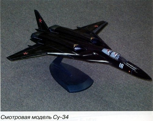
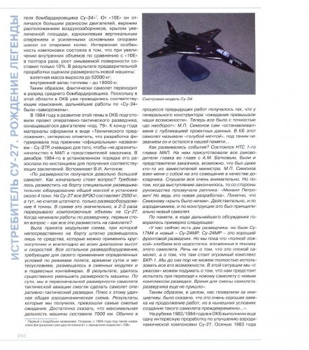
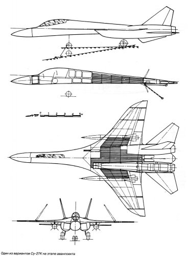
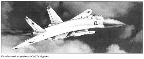
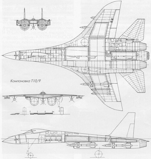
paralay said:Истребитель Су-27. Рождение легенды ч.2
")
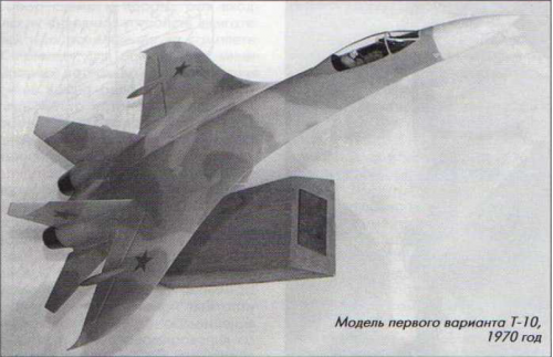
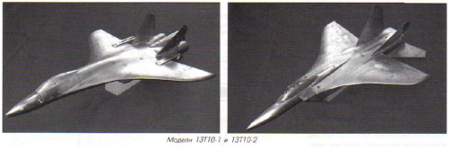
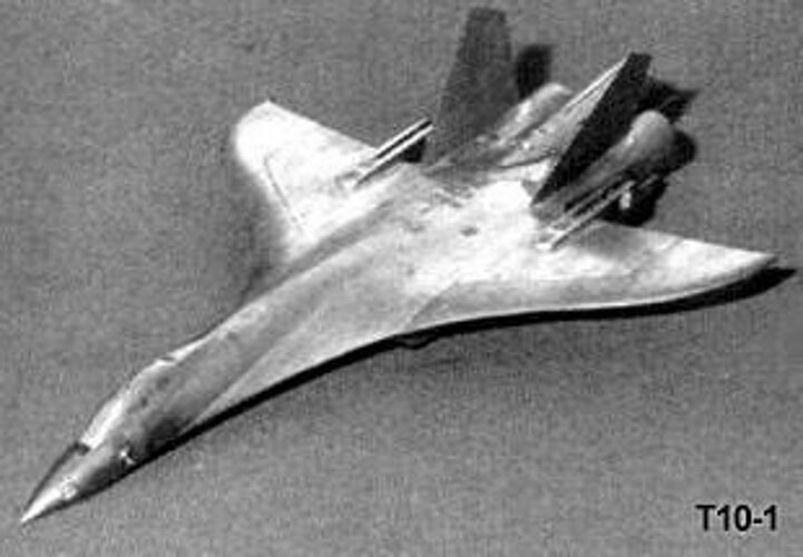
Are those fins canted out slightly? They appear so.Hi! T-10-1 model.

I sent them all in large images,why sending them again ?.Hi! Larger images.
http://aviadejavu.ru/Site/Crafts/Craft21416-6.htm
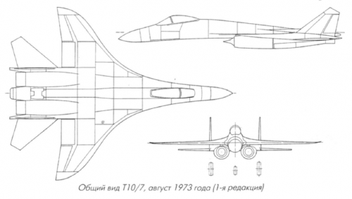
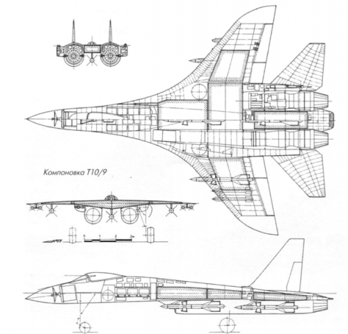
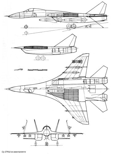
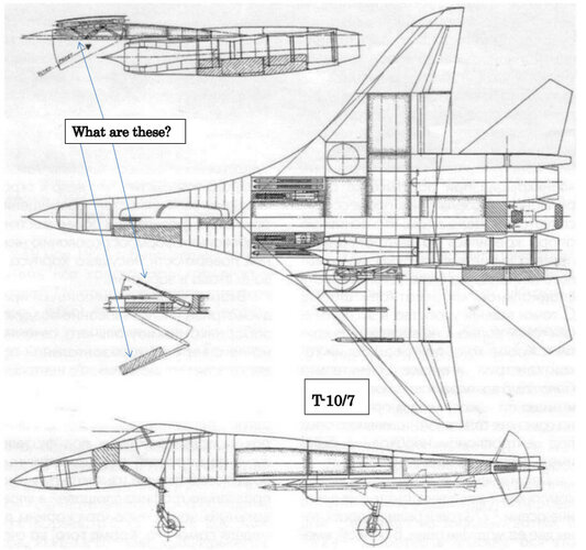
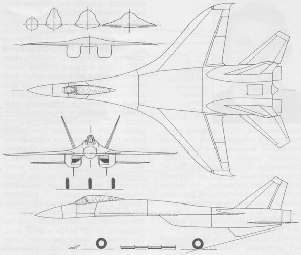
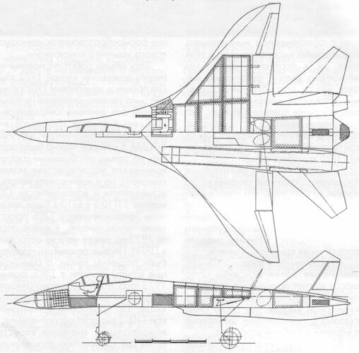
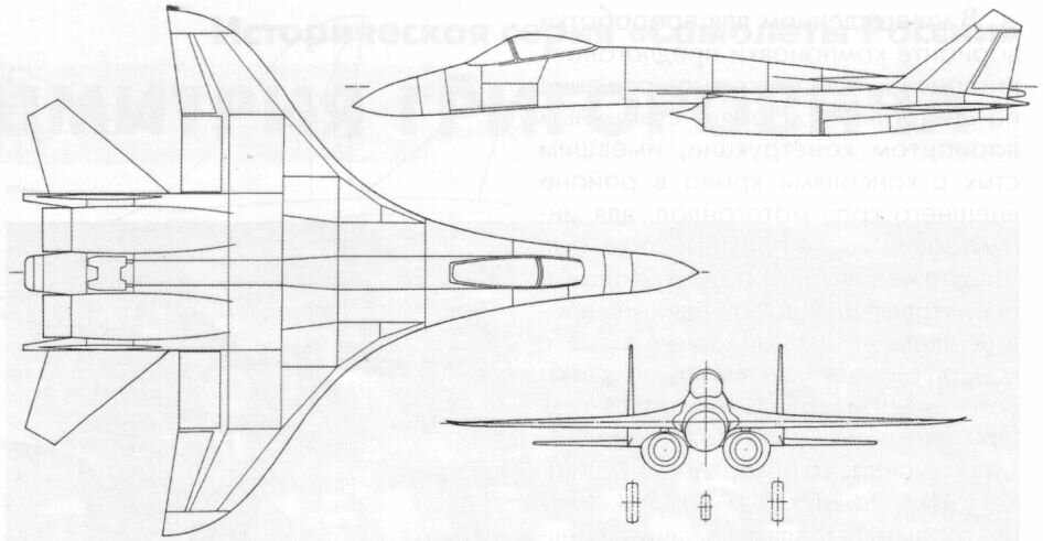
If I had to guess, it seems to be some sort of internal missile stowage (two per side) and two twin-barreled aircraft canons (GSh-23?).Hi! I want to ask these questions.
It might be the PPU-27 moving gun installation.Hi! I want to ask these questions.
Part of the tests between the VPU-687 – built-in fixed gun installation or a flexible mount based on theoretical studies that showed great benefits to such a system in dogfights.PPU-27 - moving gun installation in the same layout volume as the VPU-687, with the gun being steerable through +5 ° in the horizontal plane and 0-15° in the vertical plane, upwards from the axis of the aircraft, with an ammunition load of 150 cartridges.
DEVELOPMENT OF SU
Hi everyone! Any help?
There is an English version of 'Su-27 Fighter... 'For what purpose?
The book you need is this:
"Su-27 Fighter: Beginning of Story" by Ildar Bedretdinov et al.
It has full details and drawings of every variant studied up to the T-10 prototype in exhaustive detail. The second volume (not out in English yet) covers the rest of the story.
The SIBNIA perspective of the T-10 to T-10M, from AviaPanorama Magazine 1997 No 4 and No 5.Siberian hardening of the Su-27
The undisputed "highlight" of the last major air shows in the world are Su-27 family aircraft created at the Sukhoi Design Bureau under the leadership of the General Designer Mikhail Petrovich Simonov. The basic Su-27S aircraft (serial) was the ancestor of this family. including Su-27UB, Su-30, Su-30MK, Su-33, Su-34, Su-35, Su-37. Organizers of air shows have invented a trouble-free reception of retention of visitors until the last minute of the salon's operation. To do this, they put these planes the latest in the programs of daily demonstration flights. Visitors wait patiently, and this is the picture repeats every day. Harmony and completeness of form combined with the power of the propulsion system and the effectiveness of the control system of the Su-27 and other members of the family cause strong feelings in everyone, Those who observe their flight are delighted and delighted by their friends, fiercely envied by their ill-wishers. Therefore It is no coincidence that the Su-27 aircraft is literally overgrown with legends and fictitious facts, and it is important to clarify here.
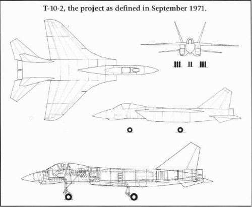
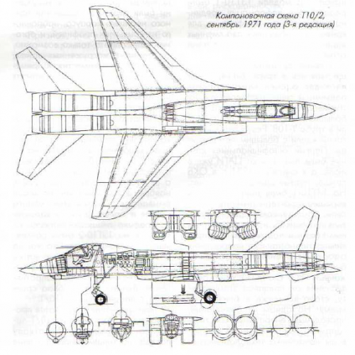
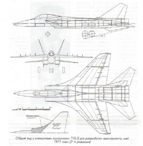
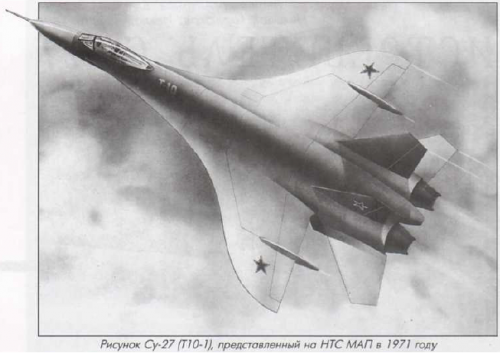
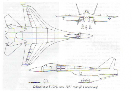
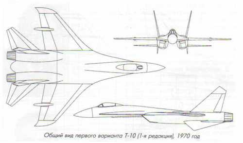
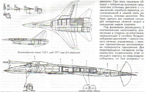
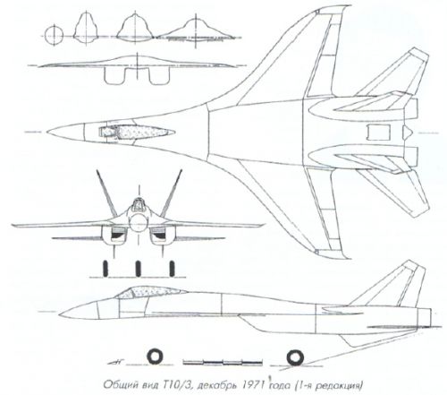
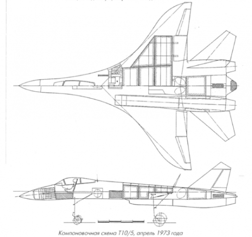
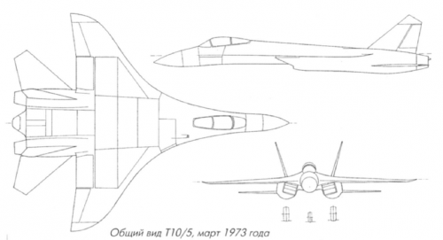
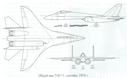
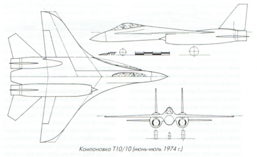
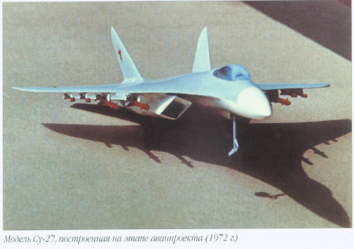
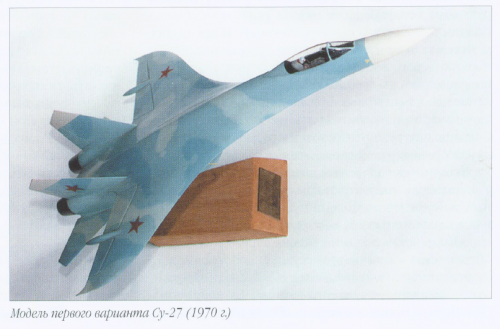
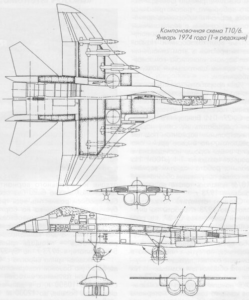
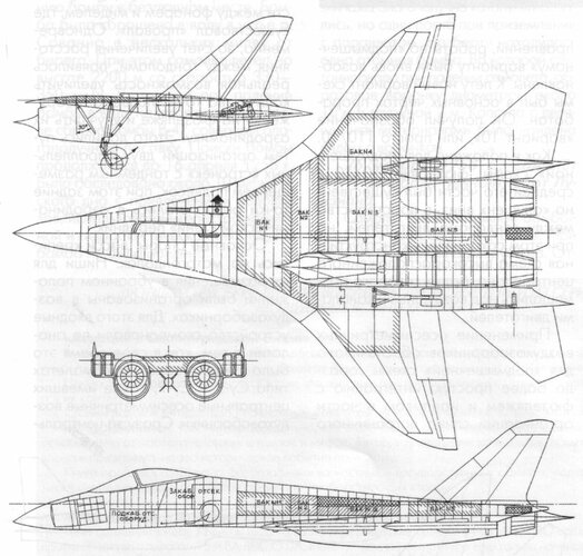
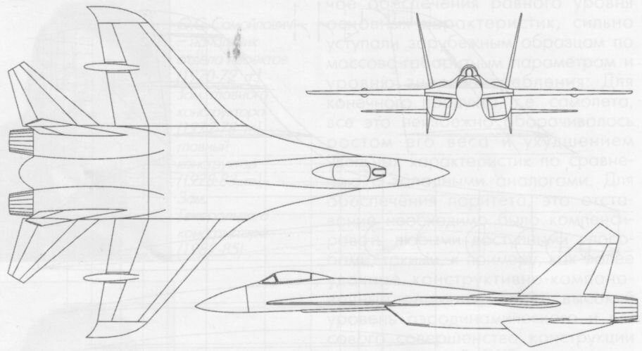
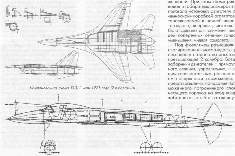
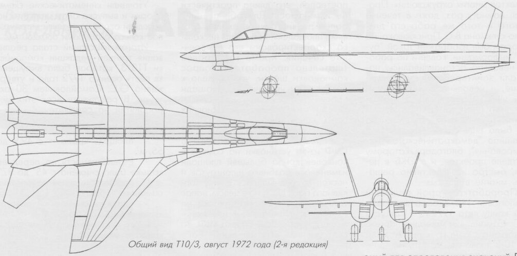
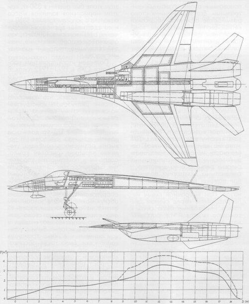
By the beginning of the 70s, there was a developed under the leadership of Pavel Osipovich Sukhoi, the general appearance of the "Gothic" in shape in the plan layout, the choice of which was largely due to its advantage in terms of resistance to supersonic mode. The layout contained a number of fundamentally new solutions and elements. She was Integral.
Two engines in separate nacelles were supposed to be "suspended" from the lower surface of the wing with maintaining a certain distance between the leading edge and the air inlet inlet. It was adopted the decision to use rear centering, which assumes the longitudinal static instability of the aircraft, and remote control system. For the first time, a serial Russian aircraft was equipped with automated fly-by-wire control system. The listed features remain The assets of the Su-27 family of aircraft, after all the improvements and changes, were important components of their success.
However, many issues of aerodynamic design of the aircraft were problematic.
It was necessary to take into account that its purpose was to fight for air superiority and that tactics included close maneuver combat, which by that time was again recognized as the main element of combat use Fighter. The designed aircraft was designed to give a worthy response to the F-15, which since 1969 had been accelerated was created by MC'Donnell Douglas. Since the F-15, according to the Pentagon's plan, was supposed to be superior to everything existing and developed fighters, an aircraft designed by the P.0.Sukhoi Design Bureau, which received the code T-10, should have been made head and shoulders above the F-15.
Where to start?
A great merit of the then heads of aerodynamic design in the Design Bureau - Deputy Chief designer I. Baslavsky, head of department M. Khesin, head of the brigade L. Chernov was the intention in-depth study of the phenomena of flow around the selected wing of the Gothic form, according to which the There was no information at the time. If the United States has already designed (F-16, F-17) and flown (F-5E) aircraft with root In our country, we had to deal with this issue from scratch. The fact is that T-10 Gothic wing with a curved leading edge, suitable for cruising on a transonic and supersonic, contains root swells integrated with the fuselage.
What will be their role and will they ensure the high maneuverability of the T-10 aircraft?
All these questions were addressed to the Siberian Research Institute of Aviation (SIBNIA).
It may be asked: why not to the head institute of the Ministry of Aviation Industry - TsAGI?
By that time, the authority of SibNIA in the field of aerodynamics was quite high. The possibility of competently and promptly answer topical questions posed by life. I've just been A great deal of work has been done on the systematic study of wings with variable sweep. Very much It was important that SibNIA designed and manufactured blowdown models as in the general industry and in the interests of one or another design bureau. Timely production of a sufficient number of models was a "bottleneck" in the country's aviation industry.
So in 1972 the epic "Su-27" began in SibNIA, which lasted 12 years.
The author was fortunate enough to be the leader and participant of this arduous work, which caused a genuine enthusiasm among all who have come into contact with it.
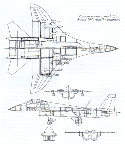
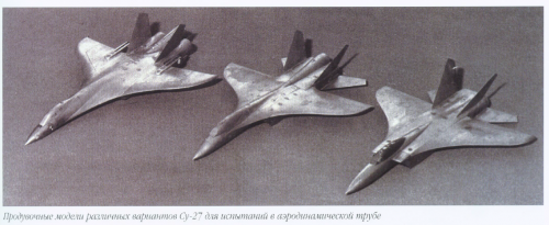
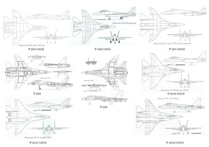
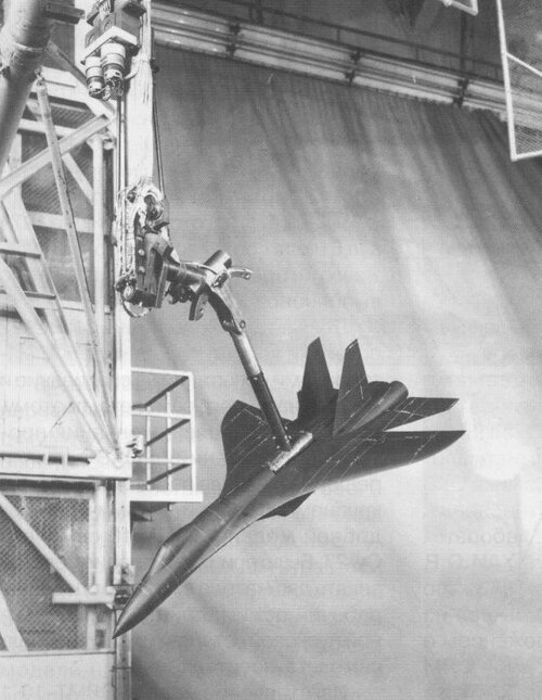
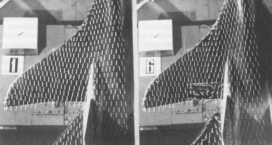
The first series of models consisted of isolated wings with the shape in the plan shown in the figure. Two wings were manufactured - a flat one and one with the first variant of the calculated optimal deformation. The goal was to study in the wind tunnel of low speeds of the T-203 SibNIA of what aerodynamicists call physical To begin with, in the area of angles of attack from 0 to 40° After testing the models on scales, tests with the use of various visualization methods - with the help of silk belts, meshes (longitudinal and transverse), oil film - a film was made about the peculiarities of the flow around the Gothic wing at the Maneuvering; The characteristics of the flow field behind the wing were also exhausted.
The models were then drilled and the pressure distribution across their surface was measured. Thus, in the In the first one and a half to two years, experimental material was obtained that was unique in scope and volume.
Starting with the first tests, which date back to 1973, we began to introduce modifications, "rocking" layout, and assess its sensitivity to change in order to find ways to improve it. Of the first The most important conclusions were made, which determined the directions for further research:
The deformation of the wing provides in subsonic cruising flight a continuous flight close to plane-parallel flow around even such a complex wing shape;
at moderate angles of attack (68°) At the leading edges, a tear-vortex flow (the term was introduced by V. Grachev) with a pair of free vortices from the leading edges is born. root swells and a pair of vortices formed on the edges of the cantilever parts of the wing (in addition to the usual terminal vortices);
These free vortices have a positive effect on the load-bearing properties and on the aerodynamic quality of the wing, therefore, they are necessary to improve the maneuverability of the aircraft;
however When the angle of attack increases above 8-10°, there is a "swelling" of vortices, a merger of inflated and cantilever vortices vortices and the destruction of the combined vortices within the wing, which is equivalent to disrupting the flow over a wide area from the ends of the wing with all the adverse consequences (the occurrence and growth of the pitching moment, impaired lateral stability, pulsation loading, the appearance of an extensive inhibited track, reduction of limiting load-bearing properties).
Thus, it became clear that a significant improvement in streamlining was required. The following tasks were formulated: Find forms of root swells that increase the intensity and stability of the root swells they generate vortices at angles of attack corresponding to maneuvering; find the means to increase the intensity and the stability of vortices occurring on the leading edges of the cantilever parts of the wing, and to prevent the early fusion of inflated and cantilever vortices, thereby increasing the stability of the entire vortex system of the wing.
When we showed a film about the visualization of the wing flow at the Design Bureau and it was watched by pilots who "morally" were preparing for flights on the designed aircraft, it became clear to many that there were angles of attack in the flight area There is an unsteady flow around the wing, which can be a prerequisite for air shaking Design. The source of nonstationarity is the destruction of vortices.
Year 1973 1974 1975 1976 1977
Number of Tube Hours 114 450 621 278 1270
Including with the flow 36 154 233 124 352
The volume of tests at SibNIA and the number of variants under study increased like an avalanche. In the first five years, the pace of The T-203 is characterized by the figures given in the table:
Along with tests in a low-speed tube, we also conducted tests in the T-205M transonic tube SibNIA and in the T-313 supersonic tube leased for this purpose of the Institute of Applied Mathematics of the Siberian Branch of the USSR Academy of Sciences. Constant and active V. Kondakova and G. Yelinov participated in these works at SibNIA. Main flow of information about features aerodynamics of the designed Su-27 aircraft came from Siberia.
At first, the project of the Su-27 aircraft was unlucky.
Pavel Osipovich Sukhoi appointed his honored and respected colleague as the head of the theme, who, However, for health reasons, he could no longer pay enough attention to this fundamentally new project. Pavel Osipovich himself was also less and less able to delve into it He died in September 1975. We reported new information to I. Baslavsky and jointly outlined program of further experiments, but all this at first had a tinge of academism. The Topic Leader has never met with us to discuss the progress of the work, although with the general contractor Pavel Osipovich Sukhi such a The meeting, however, took place. There was an impression that the design of the aircraft in the Design Bureau and the process of aerodynamic research at SibNIA was carried out independently of each other. Perhaps there was a certain factor at play here. the role of the desire to prevent changes in the project of the OKB management group, which "staked out" the author's evidence of a preliminary arrangement that has not been fully substantiated.Su-27
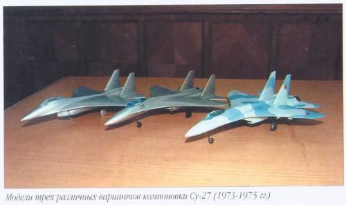
Later, it was confirmed that the leadership of the Ministry of Aviation Industry was painted a rather favorable picture development status of the Su-27 aircraft in its initial configuration. And this is despite the revealed early breakdown flow during the test of insulated wing models (approximately 10°), as demonstrated by the of the film mentioned above. Testing of the full model corresponding to the preliminary layout began in 1975 and also revealed a number of deficiencies in the effectiveness of the longitudinal control, transverse and track stability. We have identified a list of layout elements that can be weakened by changing them. or even eliminate defects. Everything was criticized: the root swells, the very shape of the wing in plan, the shape of the and the position of the horizontal tail, the layout of the vertical tail. A huge amount of the number of dissolve options, but the choice was subject to a strict limitation of the ability to create the required dive moment at any large positive values of the angle of attack. I had to choose swells that would combine a noticeable increase in the load-bearing properties of the wing with a slight increase in of the moment.
Since the aircraft was designed to be statically unstable, it was designed for balancing at high angles of attack It was necessary to deflect the stabilizer to a positive angle (with the toes up). At the same time, the lifting force of the stabilizer is folded with the lift of the wing, that is, the load-bearing capacity of the aircraft increases when a slight increase in resistance. This is the advantage of a statically unstable aircraft. But the angle of attack The stabilizer turns out to be greater than the angle of attack of the wing, and there is an early disruption of the flow on the upper surface stabilizer, which limits the maximum balancing angle of attack of the aircraft and does not allow to obtain the required margin of dive torque at the maximum design deflection of the stabilizer toes up.
When creating the F-16 aircraft, the Americans faced the same problem and could not solve it. At the exit to the angle of attack of about 50° the F-16 aircraft remains in this position, since even the maximum deviation Toe upwards at these angles does not create a dive torque. The creators of the aircraft simply entered in the control system, the angle of attack is limited to 25°.
If we take a more forward centering, that is, make the aircraft statically stable, then the problem of longitudinal balancing disappears. But the advantages statically unstable aircraft in load-bearing properties and in aerodynamic drag are so important for maneuverable fighter, which was worth fighting to find an acceptable compromise solution. On the model various ways to increase the dive moment of the stabilizer were considered, and a number of such methods were found Ways. At the same time, completely non-trivial results were obtained on the mutual influence of the wing and Stabilizer.
In the process of searching for a solution, we also set the task of increasing the dive moment of the wing by maneuvering modes. It was proposed to change the shape of the wing in the plan with a simultaneous increase in its area at the expense of the trailing edge area by straightening it and adding area behind the center of gravity. Experiences The pipe confirmed the correctness of this choice.
An obstacle to an even greater increase in the diving moment of the wing was a fairly early disruption of the flow. Together with the aerodynamicists of the Design Bureau, we came to a firm conviction in the need for deflectable toes. Confirmed by tests of full and insulated wing models. Wing twist and deflection effects Noskov was summed up, but it was impossible to predict the result in advance. I. Baslavsky said that we should protect and strengthen their decisions with a pile of reports, meaning the SibNIA reports, and they were issued before at the end of 1977, no less than 27!
In 1976, Mikhail Petrovich Simonov was appointed head of the T-10 project.
M. Simonov's approach to business was fundamentally different from that practiced by his predecessors.
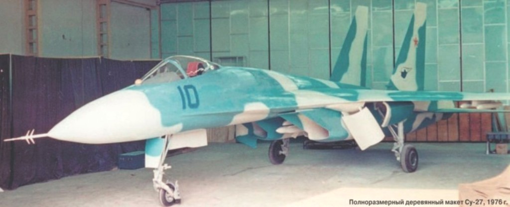
Already in 1975 - 1976 it became quite clear to us that the initial layout had significant Disadvantages. In cooperation with the aerodynamicists of the Design Bureau, a number of changes were proposed. However, the plane with was nevertheless built and took off on May 20, 1977 of the Design Bureau.
The main principle that guided M. Simonov was simple and clear: if there is a real remedy layout improvements, then you need to use it. The common "wisdom" is alien to him: the best is the enemy Good.
The second principle, which M. Simonov professed, was also simple: it is necessary to create an absolute weapon.
The third principle: M. Simonov did not consider it shameful to work directly with our Siberian Institute. We reviewed and discussed all the results obtained earlier, determined the direction of further Research. The new head of the OKB department O. Kalibabchuk was also actively involved in this work.
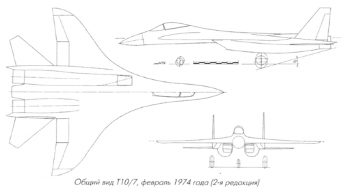
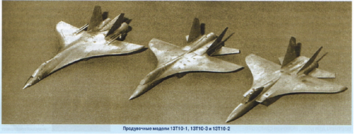
Now our work has accelerated. It was necessary to find ways to significantly increase the angle of attack, with in which there is a loss of lateral and directional stability. They began to further vary the shape of the root wing sags, angles of deflection of the wing tips and, finally, the place where the fins are installed. The most effective turned out to be the maximum separation of the keels, their installation on the beams at the root sections of the rotary Stabilizer. At the same time, the efficiency of both the stabilizer and the vertical tail has increased. On account removal of the fins from the longitudinal axis of the aircraft, the leeward keel at angles of attack over about 20 degrees turned out to be removed from the braked track of the windward wing, while the windward keel remained in this track. But leeward keel, while maintaining its effectiveness, increased the value of the angle of attack at which the loss of directional stability. Disputes about where the swamp vortices should pass when flying without slipping - between the keels or at the outer sides, - the end was laid. The question was how the inhibited a trace of windward and leeward wings when an aircraft glides. And if the windward keel with large angles of attack in any case turns out to be in the track, then the leeward keel was found a place between the companion traces of windward and leeward wings.
So, it became clear to the chief designer of the T-10 aircraft, M. Simonov, that all the elements of the aerodynamic The layout of the aircraft needs to be changed. A huge amount of experimental data obtained at SibNIA showed how to do it. At the same time, the fundamental features laid down by Pavel Osipovich Sukhoi were not subject to doubt - integrality, rear centering, remote control system (RCS), lower placement of propulsion nacelles. In 1976, Mikhail Petrovich Simonov formed a layout with a completely new aerodynamic appearance. At the same time, he introduced an extremely important element - adaptive deviation mechanization of the leading and trailing edges. This was a logical extension of the CDS functions, bringing the polar closer aircraft to the so-called envelope polar - the best of all possible for a given aircraft. Taking into account other changes in the design, power plant and onboard complex turned out to be completely new, a radically improved aircraft. But, paradoxically, it had to win the right to exist! After all, the then General Designer E. Ivanov did not see the need for significant changes to the aircraft, hoping to "bring up" the initial layout, despite the fact that in flight tests it turned out significant, and in our opinion, irremediable defects. Minister V. Kazakov accepted the proposal of M. Simonov as an attempt to "destroy the plane". Seeing the unsuitability of the original layout for highly maneuverable fighter, Mikhail Petrovich managed to defend his proposal. Design work began of the real Su-27 aircraft, which was put into serial production and became the ancestor of all of the subsequent family.
It is interesting to note that while all recommendations for relayout have been developed on the basis of the results of testing models in the T-203 subsonic wind tunnel of SibNIA, subsequent checks in the supersonic tubes and in nature showed that they did not contradict the requirements of near- and supersonic Flight.
The first production aircraft - the real Su-27 - took off on April 20, 1981, but it was preceded by an intensive work on models in the T-203 wind tunnel: in 1978 - 755 hours, in 1979 - 1068 hours, in 1980 - 860 hours. aimed at clarifying the layout parameters.
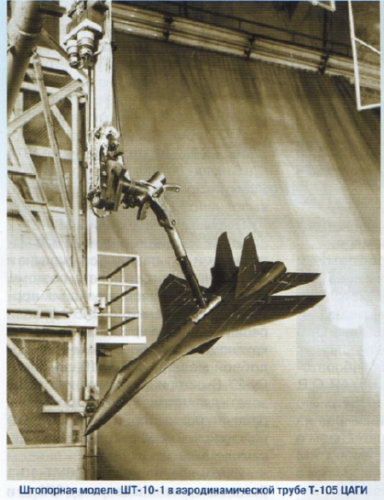
We have drawn up the terms of reference, approved by the First Deputy Minister I. Silaev and obliging to ensure the controllability of the aircraft up to an angle of attack of 90 degrees. small models for all-round testing and tests were carried out in the range of angles of attack of 90 degrees and 180 degrees. The ability to control up to an angle of attack of about 90 degrees and the presence of a very large dive is shown torque at high angles of attack, even with the stabilizer fully deflected in pitching mode. This is There was a prerequisite for the future "Cobra"!
SibNIA paid great attention to aerodynamics during unsteady movements. Y. Prudnikov were extensive experiments were carried out to study the characteristics of aerodynamic damping and revealed the regions of kinematic parameters in which "anti-damping" occurs.
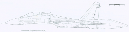
Flight tests of the aircraft of the initial layout (nine copies were produced - "experimental" series) showed, among other shortcomings, the presence of a completely unacceptable level of shaking of the structure At angles of attack exceeding 8 degrees. question about a more accurate method of predicting shaking. A joint study of SibNIA and OKB was carried out Sukhoi and LII (V. Grachev) by comparison of the total lift and distribution of pressures over the wing (stationary and non-stationary) on the model in the T-203 SibNIA wind tunnel and in flight. As an object for A 100L flying laboratory was chosen. Then in T-203 pipe, the non-stationary pressures on the wing of the T-10 model of the "experimental" layout were measured. All this made it possible to find a criterion for the occurrence of shaking. The criterion was used to analyze the test results in the tube of the serial Su-27 model. It is shown that the new shape of the wing in the plan in combination with the new shape of the root sags significantly reduces the level of pulsation loading, but the deflection of the wing tips. The flights of serial aircraft fully confirmed these conclusions. The problem of shaking was Charged.
A comparison of different approaches to eliminating shortcomings is interesting. When the Design Bureau was preparing for the first flights aircraft of the original layout, it was necessary to increase the extremely low angle of attack, at which Directional stability is lost. TsAGI recommended installing partitions at the root of the wing. Indeed, with There was a slight improvement in track stability, but at the expense of a significant deterioration in the load-bearing Properties. The partitions destroyed the vortex system of swells and accelerated the destruction of vortices on the consoles. Root influxes in this case lost all meaning.
Our approach, which was fully approved by M. Simonov, did not allow "improvement by deterioration". Painstaking tests were carried out on numerous variants of wing root swells and deflection angles wing tips, various parameters of vertical tail, the shape of the cross-sections of the nose Fuselage. Therefore, we found acceptable solutions. Our strategic principle can be described as "and/and", their principle is "either/or".
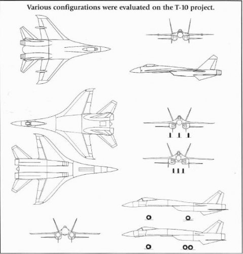
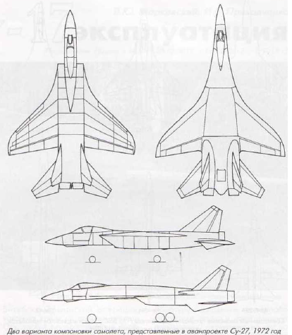
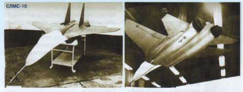
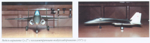
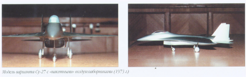
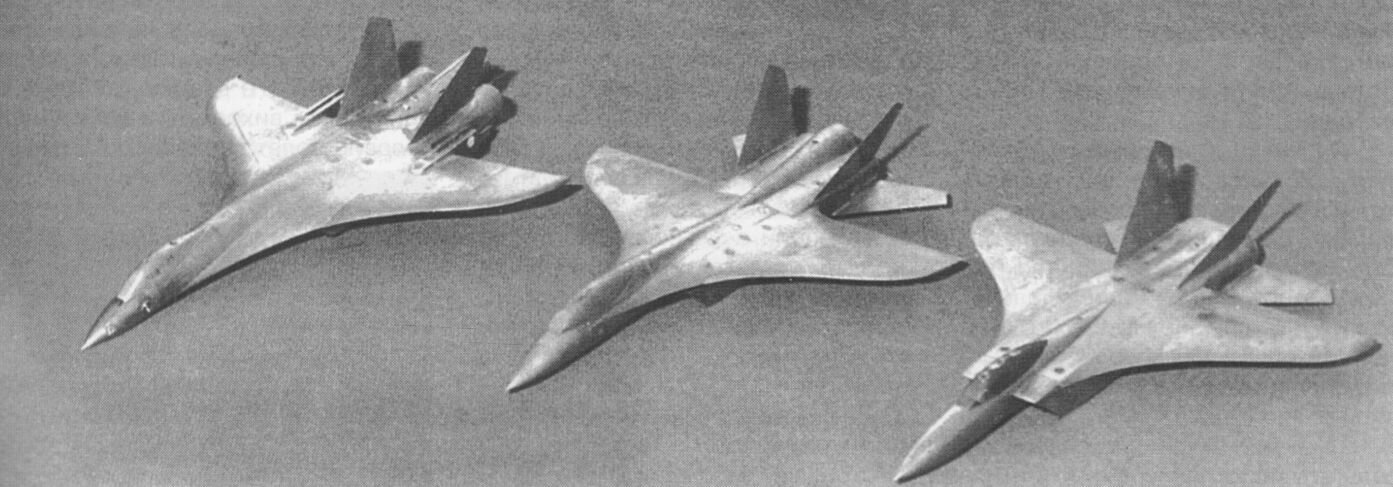
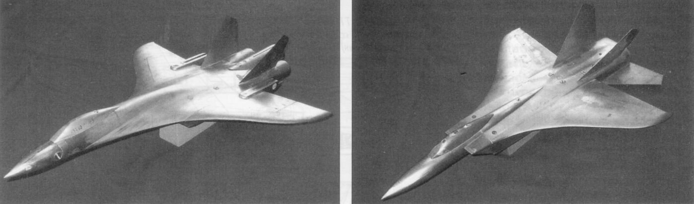
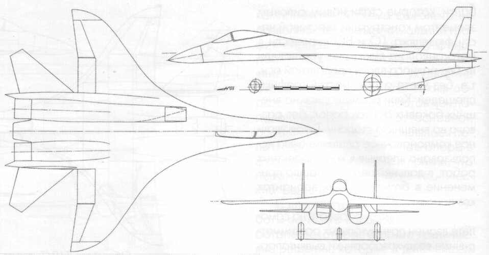
With the arrival of M.P. Simonov in charge of the Su-27 project, and then the Sukhoi Design Bureau, the horizons of our research Widened. Tests were carried out at that time of completely "exotic" layout options Su-27 aircraft: with negative sweep wings, with a front horizontal tail (PGO); Simulation of engine operation was carried out. A lot of experiments were carried out to find means of support direct control of lifting and lateral forces. A unique experiment was carried out in the T-203 tube. The screen with a moving surface simulates the rolling wheel of the nose landing gear. When working air intakes, particles were injected under the wheel, and the trajectories of their movement were filmed at the various protective devices on the wheel. The possibility of protecting engine inputs when driving was studied aircraft on the runway.
By the end of 1981, the number of scientific and technical reports on the test results issued by SibNIA exceeded 60. Was An indisputable conclusion is made in favor of the front horizontal tail as a means of comprehensive improvement of all aerodynamic properties of the aircraft. It is no coincidence that in May 1985 the T-10-24 aircraft took off (modified Su-27) with a front horizontal tail. This made it possible to install PGO in the as an integral part of the layout.
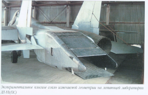
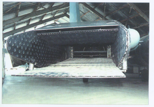
The chief, and since 1983 - the general designer of the Sukhoi Design Bureau, M. Simonov, did not abandon the idea of using controlled thrust vector. In Western literature, even then they wrote about two-dimensional rectangular nozzles as the most convenient devices for controlling the thrust vector. But M.P. Simonov chose his own path: deviation axisymmetric nozzle. We have conducted several series of tests of the model with a simulation of the operation of engines with rotary axisymmetric nozzles, although flat nozzles were also modeled. By 1985, the situation had become quite clear forces and moments arising during the rotation of engine nozzles. It was possible to start designing an aircraft and of the corresponding engine. Thus, the scientific and technical groundwork for aerodynamic Su-37 layout.
By 1985, the total volume of tests of the Su-27 model in the T-203 tube of SibNIA amounted to 10,000 hours. In addition, tests in the T-205 and T-313, but incomparably smaller. If we compare this volume with statistical data In terms of pipe hours, then there is a good coordination of the Su-27 aircraft with statistics. This It cannot be said about all other aircraft built in our country. The volume of pipe tests in our country, to unfortunately, it was always less than when creating similar aircraft in the West.
The Su-27 aircraft falls out of this statistic. Therefore, its outstanding flight characteristics and its huge development potential, which gave rise to the entire family: Su-27UB, Su-30, Su-33, Su-34, Su-35, Su-37. This family owes its existence to three sources: Pavel Osipovich Sukhoi's plan for an integral, static unstable layout; the great creative will, intuition and foresight of Mikhail Petrovich Simonov; unique in coverage of the experimental material of SibNIA.
Stanislav Kashafutdinov
, Deputy Director of SibNIA,
Candidate of Technical Sciences,
laureate State. Prize of the Russian Federation.