
You are using an out of date browser. It may not display this or other websites correctly.
You should upgrade or use an alternative browser.
You should upgrade or use an alternative browser.
Stealthy inlet duct quiz
- Thread starter flateric
- Start date
lantinian
ACCESS: Top Secret
- Joined
- 24 March 2007
- Messages
- 539
- Reaction score
- 174
Well, if I had to guess....
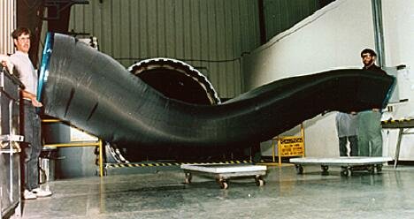
The shape suggests it was a 1 inlet per engine design. So either a single engine 1 inlet or two engine 2 inlet.
The type of curve (strong but strictly one axis) would suggest a vertical S moment not a side of mixed (side+vertical) one. That would rule out the two engine configuration.
Actually, if you turn the picture upside down, you will likely see a stealthy F-16 type of chin inlet design forming around the shape of the inlet. The main weapons bay is hiding in the cavity behind the inlet, which is shark mount in shape.
B)
- Joined
- 4 May 2008
- Messages
- 2,439
- Reaction score
- 762
I agree with lantinian's assessment. It should be for a single engine aircraft.
Just judging by the size and diameter of the duct, it should be something bigger than X-45
But which aircraft?
Could it be that there was no aircraft and it was a manufacturing technology demonstration?
Of course, this is a much less exciting explanation")
Just judging by the size and diameter of the duct, it should be something bigger than X-45
But which aircraft?
Could it be that there was no aircraft and it was a manufacturing technology demonstration?
Of course, this is a much less exciting explanation
My first thought was the Bird of Prey but I think it might be a bit too big ???
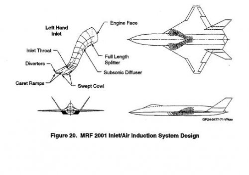
Looks a bit like one of the ducts for a MRF study in this thread http://www.secretprojects.co.uk/forum/index.php/topic,2392.msg49723.html#msg49723 but the wrong way up.
Looks a bit like one of the ducts for a MRF study in this thread http://www.secretprojects.co.uk/forum/index.php/topic,2392.msg49723.html#msg49723 but the wrong way up.
flateric said:are you kiddin'?
sorry Flateric, that was a bad idea. Post removed
sferrin said:Could just be a practice shape they were testing a new layup machine on.
That, and it could be a test shape to attach to an actual turbojet, to see how such a serpentine inlet would actually survive. Built poorly, the inlet would collapse, or at least crack. Doing such tests early would provide good data for actual designs later.
Just a theory.
shockonlip
ACCESS: Top Secret
- Joined
- 29 January 2008
- Messages
- 605
- Reaction score
- 57
It's obviously a big slinky the engineers play with at lunch.
Judging from the happy faces.
When they are done, they put it back in its container in the wall (as you can see in the background).
There is a black program exploring stealthy slinky's, but you didn't hear it from me!
Yes, I think it is an inlet duct too. Note the rectangular cross section
at the right and the circular cross section on the left (hard to see but looks
circular).
Gavin said:Maybe?
It's certainly in the same family. THe photo seems to show the inlet as bilaterally symmetrical (meanign a single engine design), but it's hard to be sure.
Similar threads
-

-
-

-
 BAE STOVL patents - P.1175, P.1185, P.109, P.112, P.115, P.1218
- Started by Mike Pryce
- Replies: 1
-
