"Source Grading"

Orionblamblam

ACCESS: USAP
Top Contributor
Senior Member
Joined
5 April 2006
Messages
11,734
Reaction score
9,140
Website
www.aerospaceprojectsreview.com
Those who bought my "US Bomber Projects Preview" probably noticed the "source grade" I used to describe the quality of the drawings used to create the new general arrangement drawings. Since then, I have revised and refined the concept, with the help of Dennis R. Jenkins and Robert Godwin, two other "project" authors who have declared the idea valid and something they'll use in the future. In the latest issue of APR, I have a two-page article describing the concept in greater detail. In the intersts of spurring discussion, I'm posting the article below...

In this issue of APR, you’ll find a great many drawings produced by yours truly. There are a few reasons for this… it allows for numerous designs to be shown in scale, it eliminates (or at least reduces) possible copyright/intellectual property issues, and, most importantly, it means that new high quality drawings can take the place of the original drawings, which are often of dubious quality.

This is hardly a new concept. Many books produce new three-views rather than showing the original drawings. However, when the original drawing is not shown, it is difficult, if not impossible, for the reader to determine just how accurate that new drawing may be. Often, especially in the case of “Luftwaffe, 1946” books, the drawings are based on scant description at best, and can often be described as pure invention on the part of the draftsman. But without further information, that is not known to the reader. As a result, many designs that can be safely described as inaccurate nonsense gain cache as “real.” This is a particular annoyance to me, and one I don’t wish to contribute to. Consequently, all drawings will have an indication of the “reliability” of the drawing, through a simple grading system, 1 through 6.

 A “source grade” of 1 indicates that the drawing is a provisional reconstruction, based on text description, not actual drawings.
 A “source grade” of 2 indicates that the source drawing is at best crude, often a notional design with just a sketch. Alternatively, the source image is an isometric or perspective artists impression rather than orthogonal drawings.
 A “source grade” of 3 indicates that the source drawings are serviceable but simple.
 A “source grade” of 4 indicates that the source drawings were clear, but the design was not entirely detailed.
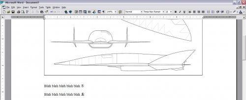
 A “source grade” of 5 indicates that the source material was detailed, clear and unimpeachable.
 And finally, a “source grade of 6 indicates that the drawing presented is the actual source drawing, not a reconstruction. A grade 6 drawing can thus run the gamut from blurry to crystal clear, from spartan to detailed.

In consultation with several other authors (including Dennis R. Jenkins, author of “Hypersonic The Story of the North American X-15” and “Space Shutlle, The History of the National Space Transportation System,” and Robert Godwin, editor of Apogee Books’ “NASA MissionReports”), this system has been refined, and changed somewhat from when I first used it in “US Bomber Projects Preview.” Grade six has been added, and instead of text describing the source grade, a standardized graphic has been created. A numeral, one through six, inside a circle inscribed within a square will be added to the drawing, either within the body of the art itself, or at the end of the caption (in this issue of APR, the source grades are located at the end of the captions). The intent is to be clear yet unobtrusive.


In short, the source grade is a measure of how much you can trust the drawings you’re looking at.
 
grades.gif


Here are some examples, showing the original source and what the grade would be for a reconstruction based on it.

grade%201%20example.gif

A reconstruction based on a pure text description rates
grade%201x.gif


grade%202%20example.gif

A reconstruction based on an artists impression to create a 3-view rates
grade%202x.gif


grade%202a%20example.gif

A reconstruction based on a very crude 3-view rates
grade%202x.gif


grade%203%20example.gif

A reconstruction based on a very simple, but basically accurate, 3-view rates
grade%203x.gif


grade%204%20example.gif

A reconstruction based on a clear 3-view rates
grade%204x.gif


grade%205%20example.gif

A reconstruction based on a “perfect” drawing rates
grade%205x.gif
 
I think its a good idea. Previously you had no clear idea whether the drawing in a book is accurate or not.
 
Really good idea indeed, will add this in the future ! Problem is, in my opinion, that
drawings could be rated as "3" or "4", because they were based on orthogonal drawings,
maybe even quite detailed ones, whereas others only get a "2" rating, as they are based
on artists impressions. But even a detailed drawing can be faulty, whereas an artists impression
can be of photographic quality ...
And even if this system would find its way into most of the literature, there probably would be
very often the temptation, to use it as an instrument of promotion and so the value probaly
would degrade quite fast. Who would buy a book, which only contains "1" or "2" drawings ?
 
Jemiba said:
Really good idea indeed, will add this in the future ! Problem is, in my opinion, that
drawings could be rated as "3" or "4", because they were based on orthogonal drawings,
maybe even quite detailed ones, whereas others only get a "2" rating, as they are based
on artists impressions. But even a detailed drawing can be faulty, whereas an artists impression
can be of photographic quality ...

This was bandied about for a while The issue with artists impressions is that you can never be sure of jsut how accurate your three-view is based on some perspective view... even if that view is a photograph. Witness the stunning inaccuracies with early reconstructions of the SR-71 and the F-117 based on actual photos.

I was of a mind to have a "2 degree" system... grades 1-6 or so for the level of detail of the original drawing/image, and A-F for the actual quality of the drawing. I've seen some staggeringly detailed blueprints that had been reduced to garbage by water, photographing onto microfil, crappy printers, exposure to sun and finnally a few years of cats peein' on 'em. But the general concensus was that 1-6 was detail enough, given that the current industry standard is nothing whatsoever.
 
Nice idea Scott!! :)

And...emh...what is the rating for (e.g.) these ones....?? ;)
 

Attachments

  • NF 104.jpg
    NF 104.jpg
    367 KB · Views: 244
  • NF104_cutaway.jpg
    NF104_cutaway.jpg
    141.9 KB · Views: 258
As the F-104 is well known, even from inside (a lot of them showed their intestines
scattered around at many places in Germany ... ::) ) and the type is well documented,
I would opt at least for "5".
But remember : Even Mike Badrock, for me the king of the cutway, the pope of the
technical aviation drawing, made some cutaways just by guessing, would it could look
like inside !
So for real clarity about the reliability, Scott's system would be far better !
And as usual, the winner is the seconds best !
 
"...you can never be sure of just how accurate your three-view is based on some perspective view... even if that view is a photograph."

We had the theme of reconstruction of 3-views from perspective views, mostly photos, several
months ago, but as it was mentioned again here, I would like to misuse this thread:
Is it possible, to reconstruct a 3-view from a photo, IF length and span are known ? Of course,
another limitation is, that it has to be a suitable photo, no head-on view.
(Not just an academic question for me ... !)
 
overscan said:
Those early F-117 drawings show how tricky making a 3 view from a single photo can be.

Absolutely quote Overscan and Jemiba, by my side it's almost impossible to have a correct three views starting by photos, even if have dimensions in your hands...
 
Three-views from photos, *especially* photos taken from close up, cannot be relied upon as accurate, the effect of perspective, especially when you don't know the cameras focal length or distance from the target, can make things a mess. You can often get *real* close, but you can't be *certain* of it.
 
To be more specific :
Apart from dimensions, preferably length and span, we need a photo, where the
endpoints are recognisable (That's a problem, especially for aircraft on the ground !).
Ideal would be the object (aircraft, of course !) in the center point, but as published
photos often are only cut-outs from the originals, so you cannot be sure about that.
And artist's impressions often are too much "art" ...
But apart from the mentioned limitations it should be possible. The relation between
length, span and the angle betwen them should be unique, I think.
 

Attachments

  • example.JPG
    example.JPG
    54.2 KB · Views: 106
Jemiba said:
But apart from the mentioned limitations it should be possible. The relation between
length, span and the angle betwen them should be unique, I think.

Ah, but that's the problem. Length, for instance. Is that "length overall?" Is it "length of fuselage?" Does it include the pitot tube on the nose? Does it start where the nose *actually* starts, or from the *theoretical* apex?
 
I suppose that appropriate software exists - at least that's one that would be used for for Photo Intelligence results processing at NSA, SVR etc. Wonder if any commercial one does.

BTW, from Charles Fleming (hope he would not mind):
"We were the first to publish accurate drawings of the F-117 [in Aerofax Extra] after Jay [Miller] got invited to the pre-public unveiling of the F-117 at Nellis Air Force base in the spring of 1990. The USAF let him take as many pics as he wanted as long as he didn't touch the aircraft, so he handed me a stack of black-and-white pics about 4 inches thick and said "have at it"; we knew the dimensions thanks to [...] so I made a wire-frame model and worked-out all the facets based on his photos. After the book was published in the fall of 1990, Jay got a call from the Pentagon wanting to know where the drawings came from; evidently even Lockheed's drawings had deliberate inaccuracies, so some feathers were ruffled at the top of the USAF command chain!"
 
flateric said:
I suppose that appropriate software exists - at least that's one that would be used for for Photo Intelligence results processing at NSA, SVR etc. Wonder if any commercial one does.

Almost assuredly. Sometime in the late 1990's I saw an ad for some piece of software that would take photos of an object taken from multiple angles and create a 3-D computer model of it. The example used was a car. The results were... unspectacular, but appeared reasonably accurate.
 
In the pre-electronic-confuser age, your best bet was to take an intelligent guess, or use best data, on a length/span relationship.
The next step was to draw two lines, one from nose to tail and one from wingtip to wingtip.
From there, you could construct a grid - a non-orthogonal grid, but with parallel lines in each direction.
Now, given what you think the primary dimensions are, plot the basic shape proportionally on the grid. There is a lot of TLAR (that looks about right) involved.
Where it gets atomically fubared is when you have no idea what the dimensions are and the pic is drastically foreshortened.
As far as I understood it, back in the days of disco, that was basically how everyone did it.
 
One thing I've often noticed in a lot of three-views (especially made in pre-computer era) is that side view, top view and front view were not at exactly at the same scale, misleading the object represented (with special reference to Spacecrafts).
This mind is also valid for NASA drawings try to take (for instance) an official STS three view and compare the the scale of each view, you may find out a lot of incongruencies...
 
I always was wandering why there are still NO accurate scale drawings of the STS...
 
"One thing I've often noticed in a lot of three-views (especially made in pre-computer era) is that side view, top view and front view were not at exactly at the same scale"

Ok, I could accept this, but there is a startling number of 3-views, were details in side, top and
front view don't match. Then it's up to you to decide, which view shows the correct postition of,
say, the wing. And even recommended books aren't always free of such errors.
So, never believe in 3-views, you didn't manipulate yourself ! ;D
 
Jemiba said:
there is a startling number of 3-views, were details in side, top and
front view don't match.

Tell me about it. It's been a recurring problem with the Bomber Projects effort

On the other hand, I've been re-drawing the Model 2050E X-20 Dyne Soar in the past few days, using drawings that I got from the Boeing Archive (thus they are not among the drawings I've released for sale). Very detailed drawings with lots of body stations, water lines, etc. And much to my utter astonishment... the angles line up perfectly, the lines to within a fraction of an inch, radii are as advertised, etc. This is a rarity for anything less than manufacturing drawings or modern CAD drawings.
 
If you look for some accurate STS scale drawing I suggest to give a look o some graphical works I did for my company, in order to fill an ASI (Italian Space Agency) Internet site dedicated to the STS-120 Mission:

http://www.esperia.marscenter.it/shudrawing.asp?lang=en
 
Jemiba said:
Ok, I could accept this, but there is a startling number of 3-views, were details in side, top and
front view don't match. Then it's up to you to decide, which view shows the correct postition of,
say, the wing. And even recommended books aren't always free of such errors.
So, never believe in 3-views, you didn't manipulate yourself ! ;D

I think that it is caused because the authors are doing every view independently. Using that method, you can of course make a lot of errors. In my drawings I connect every view with the others, so as a result, there is not any chance that something dont match.
 

Attachments

  • drawing_prototype.jpg
    drawing_prototype.jpg
    53 KB · Views: 135
Hi everybody

The second little Picture. What is this ! A VTOL-Tailsitter with prone position pilot ?
http://up-ship.com/blog/?p=2809
http://up-ship.com/blog/wp-content/uploads/2009/06/grade-6-example.jpg
It looks very cool !

Thanks
 
I would like to raise another question, as Scotts characterisation of the six different s
ource grades is clear, but fits especially projects.
What’s the source grade for a drawing, that is based on a source drawing with grade 3
or 4, but with additional detailing from photos ? Not possible for projetcs, of course and
yes, I know, that the SPF IS a special forum about projects, but it deals with prototypes
and rare one-offs, too. ;)
Grade 3 or 4, as for the source drawing only wouldn’t do justice to the result, I think, as
you couldn’t tell then a drawing, where details were just added by guessing from another
one, where a walk-around (in itself a very worthwhile source) was used . Another example
would be the combination of two source drawings, a simple one without details and another,
detailed one, but suffering from poor proportions. ???
 
Jemiba said:
I would like to raise another question, as Scotts characterisation of the six different s
ource grades is clear, but fits especially projects.
What’s the source grade for a drawing, that is based on a source drawing with grade 3
or 4, but with additional detailing from photos ?

I'd say it's still a 3. The grading system is of course subjective (except for 1 and 6, which are unambiguous), but is basically a way to tell the reader how "trustworthy" the reconstruction drawing is. If the reconstruction drawing is based on a somewhat shaky foundation... even if specific, unambiguous details are added in later, it's still a shaky drawing.

For example, something I wanted to do as an APR article for a while but eventuially rejected (largely on copyright grounds) was an article presenting a number of the first drawings of the A-12 (SR-71 predecessor) as done by the aviation media at the time of the release of the first photos. Av Week, Flight, etc. all set their analysts and artists to work cranking out three-views and cutaways based largely just on some side-view photos. So even though some details were clearly visible in the photos, the resulting 3-views were *all* dead wrong in plan view, since there was missing info. The resulting 3-views were all at a very low level of reliability, despite having clear photos with details.
 
...to say it in general, source grade tells you how close is the drawing to the reality, not how detailed it is or how nice it looks.

So as I understand it, when you have the drawing with the source grade 3 and you add additional details from the photo, than if you perfectly match the reality (less often situation), then the source grade can increase to 4, but when it will not correspond, it can also degrade to 2.
 
GAAAHHHHRRR! Had a really good, really long missive all written, ready to hit "send," and the computer burped and took the whole thing away. Bah.

Matej said:
...to say it in general, source grade tells you how close is the drawing to the reality, not how detailed it is or how nice it looks.

That's it in a nutshell. The person looking at the drawing can tell just by looking at it how detailed it is or how nice it looks... but he probably *can't* tell how accurate it is.

So as I understand it, when you have the drawing with the source grade 3 and you add additional details from the photo, than if you perfectly match the reality (less often situation), then the source grade can increase to 4, but when it will not correspond, it can also degrade to 2.

Not a situation that will occur often for "projects," but on a limited basis, I'd agree with this for reconstruction drawings for "actual" aircraft, or at least those that get to the high-fidelity mockup stage.


The purpose of the "Source Grade" is trust... how well can we trust the reconstruction to be accurate. And the reader needs to also trust the reconstructor to be honest. IF by some chance "source grading" takes off and becomes "industry standard," you can bet that some jackass will take a worthless scribble and convert it into a detailed, possibly believable three-view... and claim that it's a "4" or a "5." But if the dishonest reconstructor is found out, his reputation will be damaged.

I understand the urge to present as many "4s" and "5s" as possibel as opposed to "1s," "2s" and "3s." But especially with "3s..." who here would turn their nose up at a really well-done reconstruction rated as a "3?" Even a "2", based purely on photos of a display model or off of artwork - Lantinian's FB-23, Lantinian/Matej's DASA TDEFS spring immediately to mind - remain magnificent pieces. So long as they are pointed out to be "2s," there's not a thing wrong with them, and not the slightest bit to be disappointed* or ashamed about.

*NOTE: ok, it's acceptable to feel disappointed that Northrop has not released detailed diagrams of the FB-23, but that's beside the point...
 
"Not a situation that will occur often for "projects," but on a limited basis,... for "actual" aircraft"

That's exactly the case I'm talking about.

"the person looking at the drawing can tell just by looking at it how detailed it is or how nice it looks... but he probably *can't* tell how accurate it is"

I noticed, that even for actually built aircraft, it is often just possible to tell "how nice it looks". Maybe lots of rivets, panels .. but used just randomly to fill the areas. Or, even the smallest details you can
find on a photo, but .... measuring sometimes show, that for applying them the nose had been slightly elongated, or the fuselage had been widened a little bit to fit the markings (something that often can
be observed on colours profiles).
But with a serious effort, I think it is possible to make a detailed and accurate 3-view using a basic one
plus photos and that could be claimed by increasing the grade from maybe 3 to 4, as Matej said.

"But if the dishonest reconstructor is found out, his reputation will be damaged"

That's how it should be !
Again, my question is, if the additional use of photos shouldn't be indicated with the source
grade.

Well, you've probably noticed, that I've a personal interest in this system (and have already used it),
as it would ease the use of drawings in general. No need for long explanations, just a symbol at the
bottom ! The source grade, of course, isn't a school grade, so there isn't any need to "push" a drawing
to a 5 or even 6 .... as long, as it becomes apromoting argument for selling a book ("... contains 5 and
6 grade drawings only !" ), then maybe it will become doubtful. ::)
 
Hi everybody

Maybe someone can answer the question ? Please .
The second little Picture. What is this !
A VTOL-Tailsitter with prone position pilot ?
http://up-ship.com/blog/wp-content/uploads/2009/06/grade-6-example.jpg
It looks very cool !

Thanks
 
Looks good, but it's a little bit difficult to handle, I think.
And AFAIK, Scott proposed a symbol like the one below.
You can quite easily make a separate font of it and use it
via your keyboard.
Of course, yours would be better for printed publications.
 

Attachments

  • grade1.GIF
    grade1.GIF
    11.3 KB · Views: 53
I am going to make the drawing public in vector .cdr, .pdf and bitmap .jpg format. I just wanted to know, if it is better/worse for use compared to Scott´s symbol.
 
Here are both versions, shown in the scale at which they would be used, and used in the normal sort of context... the source grade notation at the end of a picture caption. A screenshot of a Word document seen at "page width," which would be the most probable size as seen on a computer screen, and shows the approximate resolution if the page is printed.

Note that the new version loses all its details at this scale.
While it's a visually more interesting figure than my admittedly simplistic concept, the new one has a lot of needless redundancy (the numeral "5" and five dots; the words "Source Grade"), and these get lost once the figure is actually used.
 

Attachments

  • sources.jpg
    sources.jpg
    96.8 KB · Views: 104
Its going to be THAT SMALL?? :eek: Wowh, I though that it will be the part of the drawing some 15 x 15 mm in size. Okay, for that sort of using is your symbol better for sure. I will use mine on my drawings, because it is there large enough.
 
As I promised, here it is - freeware:

Vector format (CDR):
http://www.hitechweb.genezis.eu/source_grading/source_grading.cdr

Bitmap 600 dpi (TIF):
http://www.hitechweb.genezis.eu/source_grading/source_grade_1.tif
http://www.hitechweb.genezis.eu/source_grading/source_grade_2.tif
http://www.hitechweb.genezis.eu/source_grading/source_grade_3.tif
http://www.hitechweb.genezis.eu/source_grading/source_grade_4.tif
http://www.hitechweb.genezis.eu/source_grading/source_grade_5.tif
http://www.hitechweb.genezis.eu/source_grading/source_grade_6.tif
 

Similar threads

Back
Top Bottom