Some questions about the Heinkel He 219's Nacelle Thrust Line

Thanks Dan. Fair enuffski, no worries. Not trying to pick holes in anyone either, Artie, sorry if I came across like that.
 
It is alright to include speculation and tentative conclusions. As a researcher with 40 years of experience, conclusions, tentative or not, are good only at the time of publication. More documents may come to light, as is the case here. I will also add that I've read 'historical' articles online that are distorted, incomplete and biased. And some without the necessary statements regarding any speculation. Trophy brigades (Трофейные бригады) was the Russian name for their exploitation teams.

I have a background in photography and perspective drawing. The following example is meant to be simplified. Say you have an aircraft that is exactly 30 feet long. Let's give it a fuselage height of 8 feet. Now imagine the fuselage, minus landing gear, suspended above the ground at the same height as your eyes, with your eyes at the middle of the 8 feet. You are standing at the exact middle lengthwise at 15 feet. You cannot stand too close since part of the aircraft will be outside your field of view. So you back up until you can see all of it.

Now, take a picture. If you could enclose the floating fuselage in a rectangular box that fits it exactly while being open on your side, you will see the upper left and right sides tilt downward toward the back. The lower left and right sides tilt upward. On a fuselage with a circular cross section, this will be difficult to see. It would be more noticeable in the tail assembly. That describes the distortion in photos taken from the side and assumes at least one meets the requirements I've given.

This is called one point perspective. It can be likened to standing in the middle of a straight railroad track that goes to the horizon. You know the track is straight but both of the rails converge in the distance.
 
many thanks guys.

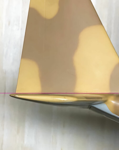
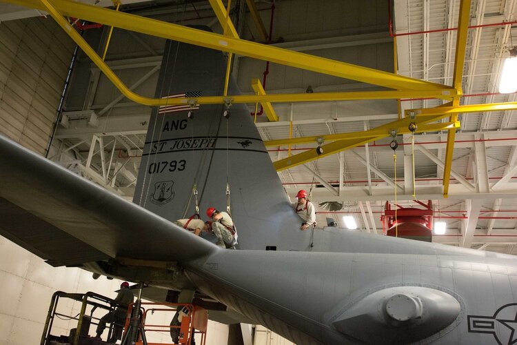
regarding this image - could it really be so simple? That the answer is that the REAR of the gondola is above the centreline and the gondola isn't tipped forward at all??

I'd say so. The shape of the nacelle--almost a tear drop but up-swept at the rear--invites the impression of tilt, particularly if perspective distorts the spinner, the propeller blades, and ends of the nacelle.
 
It is alright to include speculation and tentative conclusions. As a researcher with 40 years of experience, conclusions, tentative or not, are good only at the time of publication. More documents may come to light, as is the case here. I will also add that I've read 'historical' articles online that are distorted, incomplete and biased. And some without the necessary statements regarding any speculation. Trophy brigades (Трофейные бригады) was the Russian name for their exploitation teams.
...
This is called one point perspective. It can be likened to standing in the middle of a straight railroad track that goes to the horizon. You know the track is straight but both of the rails converge in the distance.

This brings us back to the nature of research.

We hear a lot of different views on authoritative sources, most of which are correct up to a point--as long as they don't get doctrinaire. For example, historians tend to view contemporary documents as authoritative, while scientists are likely to give more credence to physical artifacts--photographs, components, or even eye-witness observations. Nowadays, neither give much credence to secondary sources. Yet neither approach guarantees authenticity. Original documents may be preliminary, incorrect, misleadingly reproduced, incomplete, or outright false. And as we have seen, photographs can misleading due to perspective, color sensitivity of media, etc. On the other hand, secondary sources may be based on primary sources that are not presently available (almost all scriptural and classical literary/historical research is based on such sources). So, in some cases, the much derided secondary source is MORE reliable than all the available primaries put together. The bottom line is that no single source or set of sources is authoritative except relative to other available sources, critically examined.

Critical analysis is thus as important as sourcing. At a minimum, no source can be true unless what it appears to show is compatible with logic. This and several other of the more interesting above posts depend on logical assessment of the photographic evidence in light of known physical and mechanical principles. News Desk Dan's posts are convincing because they relate documents at different points in the airplane's design history and show that an angled thrust line is logically unlikely. None of them in and of itself proves anything about the "real," as-built airplane.

Finally, there was a question about qualification above. In my view, this is the least compelling support for an argument. Taken to extremes, reliance on particular qualifications can be highly misleading. Just look up the latest retractions of scientific papers published by highly qualified persons at prestigious institutions. In reality, the main value of qualification in anything is that it provides methodical training in logic and research methods (I've made my living for many years in software and computer development on the basis of degrees in Medieval European literature). So, for best results, on the evidence presented, not on the presenter.

Given the above, I still say that the mere fact that a statement is wrong, whether poorly researched or not, is no justification for disdain. I'm not pointing at any individual by any means. But I have noticed a growing tendency to intolerance in several topics of late. Tolerance for ignorance is the mark of a real expert. Intolerance suggests insecurity not authority. So my advice is to educate patiently. Stress what you don't know whenever you assert something that you do. Don't condemn. Because once questions bring condemnation, no will want to ask them.
 
Well said. My own research work relies on primary and secondary sources, photographs and other contemporary documents. Then yes, analysis occurs. Regarding German aircraft, some captured film footage survives of the particular aircraft in flight as is. I won't go into any design changes that may have occurred. No doubt all of the necessary adjustments were made before delivery.

People tend to follow those with qualifications. I've read scientific papers and watched some retracted for improper procedure and other mistakes. Do some correct their errors and try again? Yes. Others are simply discredited and are not heard from again.

Some training in logic should be there but much fine research occurred in the past by people who presented their case well, but who appeared to have worked it out without a degree or specialized training. No one can know what training an author has, and a list of degrees may not mean much when confronted with a particular problem. Without any training in aircraft design, and the reasons why aircraft look as they do, the researcher should contact others who do have a working knowledge to assist him. Or educate himself.

Condemning others is common on the internet. Add some profanity and perhaps the offender will stay quiet or withdraw. It's quick. It's easy. I mean, who wants to waste their time? It takes time to tell the other person why he is wrong. Showing disdain for some idiot? Sure. Why not? Don't patiently correct him or show him why you are right or think you're right.
 
It is alright to include speculation and tentative conclusions. As a researcher with 40 years of experience, conclusions, tentative or not, are good only at the time of publication. More documents may come to light, as is the case here. I will also add that I've read 'historical' articles online that are distorted, incomplete and biased. And some without the necessary statements regarding any speculation. Trophy brigades (Трофейные бригады) was the Russian name for their exploitation teams.

I have a background in photography and perspective drawing. The following example is meant to be simplified. Say you have an aircraft that is exactly 30 feet long. Let's give it a fuselage height of 8 feet. Now imagine the fuselage, minus landing gear, suspended above the ground at the same height as your eyes, with your eyes at the middle of the 8 feet. You are standing at the exact middle lengthwise at 15 feet. You cannot stand too close since part of the aircraft will be outside your field of view. So you back up until you can see all of it.

Now, take a picture. If you could enclose the floating fuselage in a rectangular box that fits it exactly while being open on your side, you will see the upper left and right sides tilt downward toward the back. The lower left and right sides tilt upward. On a fuselage with a circular cross section, this will be difficult to see. It would be more noticeable in the tail assembly. That describes the distortion in photos taken from the side and assumes at least one meets the requirements I've given.

This is called one point perspective. It can be likened to standing in the middle of a straight railroad track that goes to the horizon. You know the track is straight but both of the rails converge in the distance.
Optical distortions?
 
Every camera lens suffers from geometric distortion to some degree. Focal length causes perspective distortion if its not a "normal" focal length. Still its possibly to make a very basic estimate from photos...
219 nac 2.png 219 nac.png
 
Yes, optical distortions. A camera lens mimics the human eye which takes in an image and 'knows' it looks right. We just accept things, especially large objects, as looking right from childhood. Try the following:

Take an overhead drawing (plan view) of any aircraft. The drawing shows the aircraft as if the viewer were high above it. Every line drawn through the aircraft will be parallel and true. Now take that drawing and tilt it 45%. Draw straight parallel lines from left to right across the aircraft. Every line on the aircraft is now at an angle to the ground.

The same occurs when a 3D object rotates in the air. Take a large model you can hold. Make sure you hold it at eye level and turn it around. It's apparent shape changes as it turns in space.

For those who wish to look at the mechanics of perspective drawing, which must be used by artists to render their beautiful and accurate drawings, go here:

The camera lens avoids all of the drawing. In fact, shortly after the camera was introduced, painters were told to give up painting. The camera did a better and quicker job. And was cheaper.
 
Yes, optical distortions. A camera lens mimics the human eye which takes in an image and 'knows' it looks right. We just accept things, especially large objects, as looking right from childhood...
On the other hand, such distortions, when understood, became the basis for interpreting aerial photographs and converting images into intelligence. A knowledge of perspective combined with geometry and optics lets you determine the dimensions of objects, etc. Seen in this light, the common split-vertical arrangement of reconnaissance cameras deliberately creates distorted--stereoscopic--images and thereby extracts more information than could be had with a single, normal image.
 
Yes, reconnaissance cameras do this. The Germans were aware of this. The accurate measuring of shadows was important. I have seen a photo series where a truck filled with fake aircraft parts goes to a fake airfield. A fighter is assembled and even wheels could be dispensed with. Struts were used to make sure this aircraft, which had the correct dimensions, was the correct height off the ground.
 
Rich, i apologize if i missed something (i shamelessly only skimmed your writeup), but in your discussion of flight trim i did not see much about the elevator, which is after all the main effector for trim.
Because of changing weight, speed, and power setting, it's nigh impossible to trim an aircraft longitudinally for all flight phases. Designers rely on the elevator to make the necessary adjustments. The rigging of the flying surfaces, from a designer's point of view, can be considered optimum when you minimize trim drag over the course of the flight conditions you care about the most.
Say you're a reconnaissance aircraft; then you'd probably want your trim drag to be low somewhere around the mid-point of the mission while flying at your loiter speed, because that's where you spend lots of time. You can the minimize your fuel burn and design the smallest possible vehicle that still fulfills the mission. A fighter or a dive bomber would face different requirements and different riggings.
But even this is position, which makes sense to me, might fail for a number of reasons, some hard to guess...you mentioned some of these, things like the weight increases, installed power changes over the initial planned ones..or maybe it's something that has nothing to do with performance or aerodynamics but relates to ease of manufacturing. These things, if they don't cause too much performance penalty, are better handled with using the elevator for trim and not go through with extensive redesign that might disrupt production.
All this to say that unless you have primary sources telling you why the rigging was done a certain way, and this does not conform to a typical set up, you can only speculate as to the why. Oh, i forgot, engineers screw up a lot too! even translating wind tunnel tests to full scale does not guarantee success!
 
There is a published photo of a full-size Bf 109 suspended in front of a wind tunnel. Engineers cannot make too many mistakes or the aircraft will fall to enemy action.
 
PB 39170. Scholkemeier and Röber. Kraftmessungen und rudermomentenmessungen an einen original-leitwerk der He 219 mit rumpfstummel (Force and control surface moment measurements on an original He 219 control surface unit with fuselage stump). (Deutsche Luftfahrtforschung UM 2141) Nov 1944. 30 p[ages].

This is a report of the "Luftfahrtforschungsanstalt Hermann Göring - Institut für Aerodynamik, Braunschweig." The influence of diagonal flow on lift and control surface moment of the elevator unit is of minor nature. The same applies to influences of angles of side slip and the lateral rudder deflection on the elevator float angle. The auxiliary lift flap with a greater trailing edge angle proved to be more efficient than a flap with out trailing edge. Very little difference was noted in the effect achieved by the four lateral control surfaces investigated except that the rudder float angle was found to be greatly dependent on the pitch angle of the elevator unit in the case of the control surface with overhauling balance. Data tables, graphs, diagrams, and photographs are included. In German.

--

The above was published in Bibliography of Scientific and Industrial Reports, Volume 4, Issue 11. Published by U.S. Office of Commerce, Office of the Publication Board, 1947.

At the time, a microfilm copy or photostat of the report could be purchased.
 
" The influence of diagonal flow on lift and control surface moment of the elevator unit is of minor nature. "

what they're describing here is spanwise flow, which is the correct English term. Must be a translation thing, but i think this is what they're talking about.
Spanwise flow is either caused by sideslip, wing sweep (not our case), or the presence of something that alters the pressure distribution away from what an "infinite wing" would see. The latter case includes immersing the wing in the propeller slipstream, or near the wingtip where the wingtip vortex induces some side components. I suppose the presence of bodies like a nacelle can also change pressure distribution locally and thus flow direction.

Anyway, if you put the airplane in a crab, the air no longer runs parallel to the longitudinal axis of the fuselage. They're saying the effect on elevator effectiveness is small. This is not surprising; i am no pilot, but how much sideslip can you put on an aircraft like that? 15 degrees? You find yourself in a situation where the elevator hinge axis is not perpendicular to the airstream. The cosine of 15 degrees is 0.96...so you would expect that most forces remain the same.
My interpretation is that they are not discussing the absolute effectiveness of the elevator in general; rather, they are looking at the effects of normal amounts of yaw on the elevator authority, and finding that these effects are small.
 
There is a published photo of a full-size Bf 109 suspended in front of a wind tunnel. Engineers cannot make too many mistakes or the aircraft will fall to enemy action.
You are giving engineers too much credit! (source: i am an aeronautical engineer) :D
I wish this wasn't the case, but even with the best of intentions and lots of work, they make plenty of mistakes. Engineering is hard! Otherwise the history of aviation wouldn't be littered with cases of failure that was preventable in hindsight.
 
" The influence of diagonal flow on lift and control surface moment of the elevator unit is of minor nature. "

what they're describing here is spanwise flow, which is the correct English term. Must be a translation thing, but i think this is what they're talking about.
Spanwise flow is either caused by sideslip, wing sweep (not our case), or the presence of something that alters the pressure distribution away from what an "infinite wing" would see. The latter case includes immersing the wing in the propeller slipstream, or near the wingtip where the wingtip vortex induces some side components. I suppose the presence of bodies like a nacelle can also change pressure distribution locally and thus flow direction.

Anyway, if you put the airplane in a crab, the air no longer runs parallel to the longitudinal axis of the fuselage. They're saying the effect on elevator effectiveness is small. This is not surprising; i am no pilot, but how much sideslip can you put on an aircraft like that? 15 degrees? You find yourself in a situation where the elevator hinge axis is not perpendicular to the airstream. The cosine of 15 degrees is 0.96...so you would expect that most forces remain the same.
My interpretation is that they are not discussing the absolute effectiveness of the elevator in general; rather, they are looking at the effects of normal amounts of yaw on the elevator authority, and finding that these effects are small.
Verticals do stall. Just like a wing. Side slip is restricted by stall like any out of straight flight escape (although other aero effect my interact before).

At high speed for example (supersonic), aerodynamic loads might overstress structural integrity (read opening post in latest B-58 thread) at an hard to predict low beta (sideslip angle).

i feel like there's a confusion about what we're describing here. Flying surfaces stall if they exceed a certain angle of attack, which is measured between the incoming airflow and the chordline of the surface. The angle the German report was talking about (at least in my interpretation), was the in-plane angle formed between any of the chord lines of the surface and the incoming airflow. You are not changing the angle of attack of the surface. I'm attaching a picture, imagine that's a horizontal tail with an elevator at zero alfa, or a wing with ailerons or flaps. Left is normal flight, right you introduce a bit of in plane angle.
What the report is saying is that the force you can generate with the movable surface is not much diminished if you're in yawed flow. Nor should you expect there to be a whole lot; lots of planes have swept hinge lines on their control surfaces and they work fine within reasonable angles. yawed flow.JPG
 
Sometimes the most important parameter in aircraft design is what is known as ‘cruise’. This is the flight phase that occurs when the aircraft levels off after a climb to a set altitude and before it begins to descend. The ‘thrust line’ (an imaginary line through which the resultant thrust acts, and which may refer to the thrust axis of one engine or of the whole aircraft) maximises the pull / push effect with the higher Cl/CD position for the wing. This is sympathetic to minor alpha / angle of attack change (in positive and negative values) and helps with wind gusts in flight and the subsequent stability of the aircraft. (CI/CD refers to ‘drag curve’. Because power must equal drag to maintain a steady airspeed, the curve can be either a drag curve or a power required curve. As airspeed increases, the propeller efficiency increases until it reaches its maximum. Any airspeed above this maximum point causes a reduction in propeller efficiency.) (3)

There are quite a few basic errors in this paragraph, that if I’d bought the book would lead me to question everything!

Cl/Cd is the Lift to Drag ratio. If you were plot its curve, you would have the drag polar, which would link to the angle of attack. This is a key aerodynamic efficiency factor for maximising either range or endurance.

Power is definitely not equal to drag to maintain airspeed. Drag is a force (SI unit of Newtons) and is equal to Thrust.
 
I forgot to say THANK YOU to all involved in this thread. I've contacted some great people through it, and although I have decided not to use this little piece of research in our book, I greatly appreciate the community's effort!
 
I never noticed this topic until now, so I am a bit late at the party.
Just some remarks on the B-26 wings:
I was wondering if anyone had for example William Wolf's 'B-26 Marauder The Ultimate Look' - as far as I understand it, a direct comparison between the B-26C and B-26G should show a change in the engine nacelle shape and the incidence to the wing.
I don't know that particular book, but in Frederick Johnsen's book 'Martin B-26 Marauder WarbirdTech Volume 29' this is also mentioned and shown.

The B-26B and C had a 1 degree angle between the thrust CL and the fuselage CL (so propeller shafts pointed slightly upward).

The B-26F and G had their wings (including engine nacelles) repositioned with 3.5 degrees more incidence to improve aerodynamics, resulting in better takeoff performance and a more level cruise attitude. The angle between thrust CL and fuselage CL was therefor 4.5 degrees.
The angle between wing chord line and thrust CL was 3.5 degrees, resulting in an angle of 8 (eight) degrees between chord line and fuselage CL.
It also says: eight-degree dihedral gave horizontal stabilizers characteristic upsweep.
 
Gentlemen: please allow me to introduce a different twist to this dialogue.

I AM NOT an aviation engineer or theorist, just an advanced RC Warbird aficionado, 35 years experience specializing in multi-engine WWII era.

18 months ago, I gained access to a beautiful 1/6-scale He-219 model beautifully built by a world-famous modeler: Dave Platt. It is beautifully scale reproduction from Van Moser plans and Tamiya 1/48 plastic model, incidences measure out all around, BUT scale nacelles much too small to fit an internal combustion engine with enough power and flight controls too flimsy for a 55 lb machine. So he gave up on it and I spent the pandemic months installing electric powertrains and fortifying its guts. The plans called for the wrong CG, but by geometric and empiric determination of “mean wing chord,” I think I avoided that potential disaster. Here is a decent video of its very first flight

View: https://youtu.be/uX3WtMy9cKU


Here’s the rub. And why I found this forum: the airframe handles beautifully, power is abundant and other minor changes like automated rudder coupling will improve pilot performance, BUT it almost immediately and throughout the power curve, requires an ENORMOUS amount of down elevator trim. Once corrected, the plane was stable and nimble and docile. I’m not sure how to (whether to) correct it.

Could it be related to the debate here? Is it related to wing/thrust changes Heinkel made to improve climbing capacity above 8,000 m while underpowered and heavily armed?

By the way: the horizontal stab has an inverted airfoil. Not sure why.

Mark
 
Needing a bunch of down trim could mean you are tail heavy. You might try shifting your batteries forward a bit at a time and see if that reduces the amount of down trim needed.
 
interesting to see this topic resurrected!
Many arguments about the real He 219 come down to power as well. I've just read Calum Douglas's excellent 'The Secret Horsepower Race' which concludes that virtually all German aircraft had a deficit of power later in the war due to substandard engine parts.
and here's Eric Brown's recollection of take off - not verbatim but near enough - from 'Wings of the Luftwaffe'

…I have read German reports that, fully loaded, the He 219 enjoyed an ample surplus of power and that an engine cutting immediately after take-off or during the approach presented little danger. There was, it is said, an instance of a pilot making an emergency take-off on one engine with his undercarriage locked in the ‘down’ position and with flaps fully extended! If there is any truth in this last report, I can only say that for this extraordinary feat the aircraft must have been equipped with JATO and had a very long runway indeed! In my view, the Heinkel fighter — certainly in its He 219A-2 version — was decidedly underpowered. An engine failure on take-off must have been a very nasty emergency to handle at night as, below 220 km/h (137mph), the aircraft was difficult to hold straight and, combined with the ‘sink’ as the undercarriage came up, this meant that there was a critical area between 15.20 m (50ft) and 91.50m (300 ft) on climb-out. Unstick speed was 170 km/h (106 mph) and it was possible to commence raising the undercarriage at 15.20 m (50 ft) but not lower because of the previously-mentioned sink. As speed built up to 250 km/h (155 mph) the flaps could be raised at 152m (500 ft), this being accompanied a noticeable sink, and the aircraft could then be settled in a steady climb at 300 km/h (186 mph) with 2,500 rpm and 1.3 atas (19.1 lb) of boost. Once settled in the climb, the excellent stability characteristics of He 219 became evident. The best rate of climb was obtained by letting the initial speed of 300 km/h (186 mph) decay slowly as altitude was gained until it dropped back to 280 km/h (174 mph) at 10,000 m (32,810 ft). The rate of climb was certainly unimpressive…

 
I am not sure that Calum Douglas's conclusion is in anyway new. Many have stated the same earlier.
The crazy decade that just passed regarding the Uber-Luftwaffe probably just needed some temper to meet back History. I am glad of this.

Regarding the tail plane, an inverse airfoil is quite normal. Symmetrical's ones are used on cost ground (light airplane) or high speed airplanes (and not even always).
 
I believe the observations of the model requiring excessive trim while no such comment is made by those that flew the aircraft confirms there’s a difference between the two. This supports the hypothesis that the real aeroplane wing twist is not present once in flight even though clearly observed one ground (ie we see the wing in its 1g jig shape which untwist in response to flight loads). The model will have a much stiffer wing, thus it’s not untwisting due to flight loads, so the nacelle angle is producing a trim moment and hence requiring corrective trim to remain straight/level.
 
Last edited:
I believe the observations of the model requiring excessive trim while no such comment is made by those that flew the aircraft confirms there’s a difference between the two. This supports the hypothesis that the real aeroplane wing twist is not present once in flight even though clearly observed one ground (ie we see the wing in its 1g jig shape which untwist in response to flight loads). The model will have a much stiffer wing, thus it’s not untwisting due to flight loads, so the nacelle angle is producing a trim moment and hence requiring corrective trim to remain straight/level.
Thanks for the input and the historical verification. Most of the counsel received from fellow modelers (with little or no av engineering background) was to increase nose weight: move the CG forward, which is pretty easy to do, given its long empty nose. I am perplexed, however, by the “feel on the sticks” of the aircraft AFTER downtrim was dialed in: NOT AT ALL like the few tail-heavy aircraft I have flown. Much sweeter and more forgiving, in fact, than the various perfectly balanced P-38’s, P-61’s, B-25 and other twins I have flown in that size range.

I guess my plan is to slowly move the CG forward, if for no other reason because other fixes like changing wing, thrust or horizontal stab incidences would be major re-build jobs.

One particularly tempting suggestion was: “Just fly it with the down trim! All you’re doing is flying it in small circles at low altitude, so don’t mess with succes!”

Thanks,

Mark
 
I think a reason for having an inverted airfoil stab is to prevent an aircraft from steepening its dive and increasing its speed until it tucks and breaks up. With increasing speed, the inverted airfoil increases its downward push on the tail raising the nose and leading edge of the wing slowing the airplane down.

Flying with a bunch of down stab trim is like having a lifting stab. With increasing speed, the lifting stab will raise the tail and lower the nose and can put the plane into a steepening and faster dive.

It would be interesting to see what the incidences of the wing, stab, and thrust line are on the plan and the built model.
 
Last edited:
Hi guys - I am new here, this group was recommended to me by some guys over on Facebook.
My name's Richard Carrick, I am the MD of Chandos Publications - here's my website, not to self-promote but to show you I am a real person and not some kind of troll!

www.chandospublications.co.uk

anyway, we publish high-end books on the Luftwaffe. Our third book will be on the He 219.

We have commissioned three authors to work on the book - Kjetil Aakra, Marcel Hogenhuis and Martin Streetly. ...........................

Hi Rich,
What is the status of this new He 219 book?
Is it still in the planning, or has it been cancelled?
 
I'll leave the aerodynamic explanations to those with more specialist knowledge than I can calim.

But, I still think that we may be reading too much into our perceptions of an aircraft that has a somewhat unusual looking profile.

In my modified version of the example, the blue line shows that the thrust line pretty much parallels the ground line. The aircraft appears to sit nose-high on its landing gear, but only because the lower, forward fuselage is cut away in front of the gun tray. The equally unusual bubble canopy accentuates the effect.

Note that the red "horizontal centerline" leaves most of the fuselage depth below the "horizontal". If we continue the line of the lower rear fuselage to the nose--the thick black line in my example--the nose-high look of the fuselage and the nose-down look of the engine nacelles largely vanish. Instead, the fuselage spine slopes down to meet the top edge of a horizontal stabilizer mounted slightly below the engine thrust line. If we ignore the canopy as well, I think we end up with a fairly symmetrical airplane with a more or less conventonal appearance.
 

Attachments

  • he219.jpg
    he219.jpg
    147.6 KB · Views: 34
Something was not tested in the He-219 model was if the amount of down trim needed changed with power setting. On models, unless the thrust line is horizontally near the centerline of the leading edge of the wing, the thrustline will need to be adjusted to prevent having large trim changes with different levels of power. You can tell if a model needs downthrust if in level flight the model climbs when power is increased and the surfaces are not moved. A dead giveaway that lack of downthrust is the problem is if you have the plane trimed to fly level at one throttle setting and you cut the throttle. If it dives, you need more downthrust and you have a bunch of downtrim in to control the climb under throttle.

Something to consider is that RC model pilots watch their airplanes more closely than anyone else because that is how they control their models. The RC pilot controlling his airplane from outside it has a much more detailed view of what the airplane is doing at any moment than any full scale pilot who has to watch his instruments and feel it in the seat of his pants. The RC pilot can immeadiately see if his airplane is climbing, diving, or yawing and make corrections. It is much easier for an RC pilot to get out of a spin because he can see which way the spin is going and make the appriate moves rather than watching the scenery go sideways across the winshield and try to comprehend the instrument dials spinning.

RC flying also allows one to try subjects or manouvers that would be dangerous in a situation where your hind end is in the airplane. I've enjoyed flying in small airplanes, but all my full scale flying buddies have gone west and I am content to fly the models I build of any subject I choose.
 
Concerning aircraft with inverted airfoil horizontal stabilizers, the very well known C-130 has one. I've attached pictures of a large manufacturers model C-130 along with several pictures of full scale C-130 top and bottom of the horizontal stab so you can see the flattness of the top and camber of the bottom.
 

Attachments

  • C-130 Stabilizer 1.jpg
    C-130 Stabilizer 1.jpg
    112.5 KB · Views: 22
  • C-130 Stab Top .JPG
    C-130 Stab Top .JPG
    51.3 KB · Views: 10
  • C-130 Stab Bottom.JPG
    C-130 Stab Bottom.JPG
    38.4 KB · Views: 11
  • C-130 Stab Bottom 2.jpg
    C-130 Stab Bottom 2.jpg
    368 KB · Views: 10
I am not sure that Calum Douglas's conclusion is in anyway new. Many have stated the same earlier.
The crazy decade that just passed regarding the Uber-Luftwaffe probably just needed some temper to meet back History. I am glad of this.

Regarding the tail plane, an inverse airfoil is quite normal. Symmetrical's ones are used on cost ground (light airplane) or high speed airplanes (and not even always).
The conclusion wasnt "the engines had substandard power" anyone can see that by picking up a Motorenkarte and reading the numbers off it. The important thing to understand was WHY, and this has certainly not been stated earlier, by anyone in fact (certainly not in anything more nuanced than "they had less important stuff").
 
Back
Top Bottom