Sablatnig prototypes and projects

Jemiba

Moderator
Staff member
Top Contributor
Senior Member
Joined
11 March 2006
Messages
8,608
Reaction score
3,061
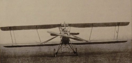
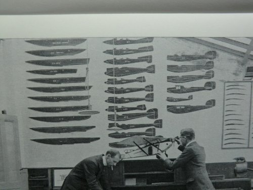
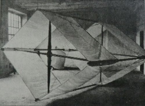
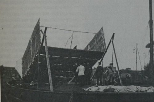
The German Navy issued a request in 1918 for a man carrying kite to be used by Uboats for
Reconnaissance purposes, just as the Focke Achgelis Fa 330 Bachstelze during WW II. The
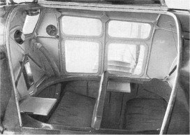
Sablatnig Flugzeugbau GmbH answered with the construction of a rhombical box kite,
carrying a gondola for an observer underneath (kite_01.jpg). The project proved to be
unexpectedly difficult. The kite of 40 sqm area needed a lot of wind to be kept aloft, not
helped by the drag of the gondola and its crab like attachement. After tests, during October
1918 a new design was stipulated, with aluminium replacing the wooden structure. On 2nd
of February a complete kite with a metal frame was delivered and tested, but the project
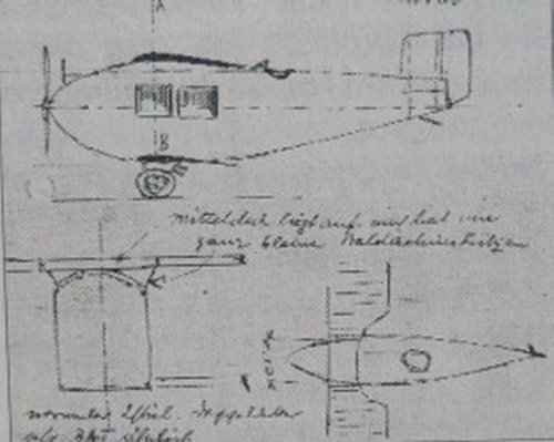
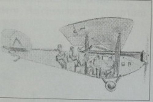
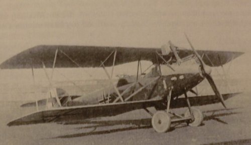
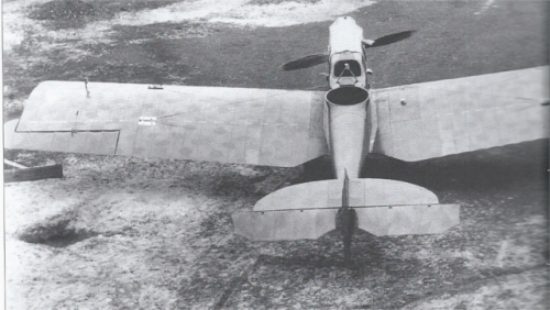
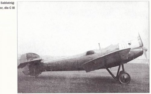
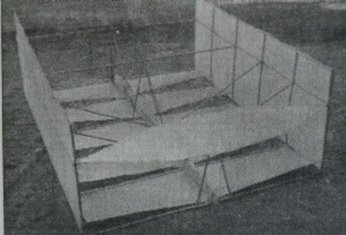
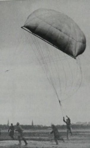
was then stopped. In 1921, when construction of aircraft still was forbidden, Sablatnig started
designing of man carrying kits again. The new idea was to design it in a way, that allowed a
gliding descent after release of the tow rope, as experience had shown the danger for the
observer using conventional kites, as a breakage of the tow rope inevitably meant a crash of
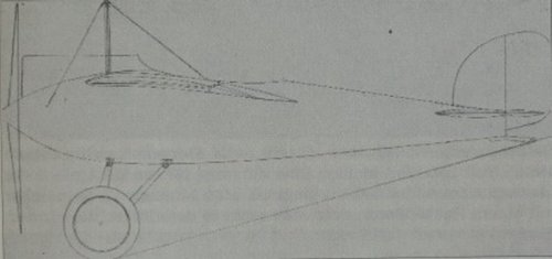
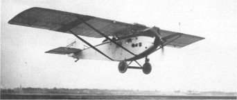
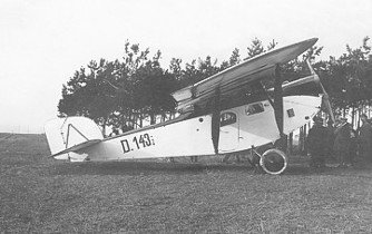
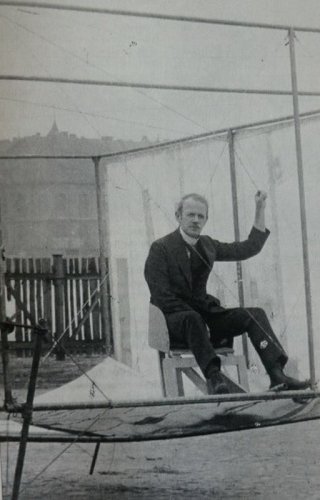
the kite. After a lot of “model tests” an example with 4m x 5m was successfully tested with
the chief designer Hans Seehase as “testpilot” in October 1921 (kite_02 and 03.jpg). An even
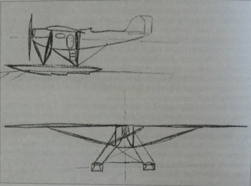
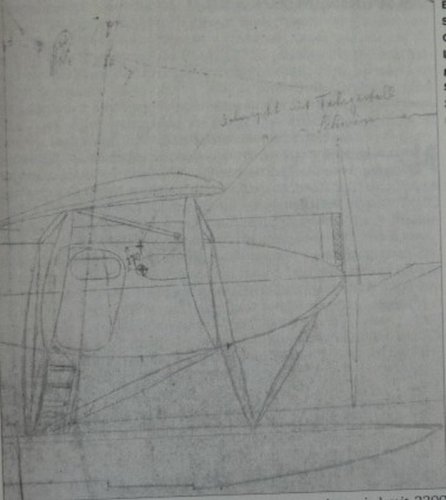
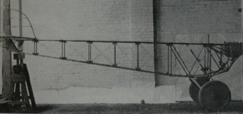
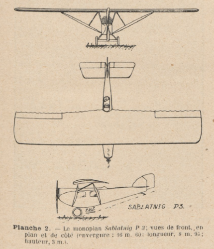
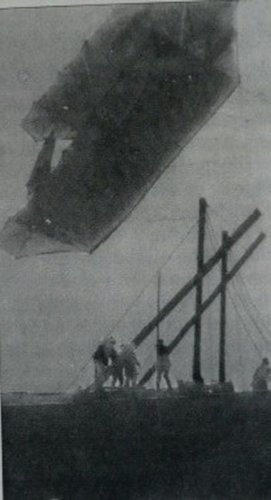
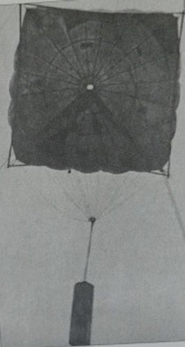
larger kite (5,5 m x 7m) was the next step (kite_04 and 05.jpg). Remaining problems were the
tendency of those kites to swing heavily, nevertheless towed by a car a height with “passenger”
of around 10 m was reached. Other experiments were made with so-called “kite parachutes”,
manned and unmanned, during 1923 and negotiations conducted with Mitsubishi, but without
results, so work was cancelled in 1924.

Photos and information from “Josef Sablatnig – Der Sablatnig Flugzeugbau und sein
Chefkonstrukteur Hans Seehase”
 

Attachments

  • kite_01.jpg
    kite_01.jpg
    141.3 KB · Views: 673
  • kite_02.jpg
    kite_02.jpg
    121.1 KB · Views: 638
  • kite_03.jpg
    kite_03.jpg
    101.7 KB · Views: 588
  • kite_04.jpg
    kite_04.jpg
    75.7 KB · Views: 558
  • kite_05.jpg
    kite_05.jpg
    85.7 KB · Views: 539
  • kite_06.jpg
    kite_06.jpg
    62.3 KB · Views: 41
  • kite_07.jpg
    kite_07.jpg
    65.6 KB · Views: 59
After this digression into the world of toys (kites ;) ), back to “true” aircraft again. After WW I,
the most successful Sablatnig aircraft was the P 3 passenger aircraft, which was used on charter
by the Luftbild GmbH in 1920 for mapping the Dutch coastline. This very successful mission,
especial in comparison with the other aircraft used (Fokker, AGO and LVG led to plans for the
design of a dedicated version of the P 3, with the cabin equipped with camera and darkroom.
After experiences of still not sufficient performances and handling characteristics above heights
of 4,000 m, Josef Sablatnig made a rough sketch of a modified version. Those plans were later
stopped by the Reaty of Versailles coming into effect.
 

Attachments

  • photographic_aircraft.jpg
    photographic_aircraft.jpg
    106.3 KB · Views: 79
  • P3_photographic_01.jpg
    P3_photographic_01.jpg
    67.7 KB · Views: 88
Excellent my dear Jemiba,


the last aircraft project is new for me.
 
The SF 10 was a project similar to the P 3, but with shoulder, instead of parasol wing, Actually it is not
quite sure, if it was a kind of follow-on, or a pre-project to the P 3, which was planned to be used as
a floatplane, too, as is proven by a handmade sketch.
 

Attachments

  • SF-10_01.jpg
    SF-10_01.jpg
    83.9 KB · Views: 76
  • P3_floatplane.jpg
    P3_floatplane.jpg
    97.1 KB · Views: 75
The sloped door to avoid the strut is neat! Excellent excuse for arbitrary styling (although I wonder if it would work better or worse in the case of a capsizing)
 
Hi,


here is the Sablatnig Exeperimental C Type,


Sablatnig Experimental C Type
These two machines were variants of the C II machine in an obvious endeavour to compare the advantages of the more normal parallel strut arrangement (above) with the I-strut system of the C II. For further comparison the X-strul cellule (below) was tried, this machine also differing in having overhung balanced elevators. Although not confirmed, dimensions were doubtless largely the same as those for the C II. Engine, 245 h.p. Maybach Mb IV.


http://flyingmachines.ru/Site2/Crafts/Craft25821.htm
 
Correct description, both variants are mentioned as "C IIa" with conventional (parallel) and
"C IIb" with X-struts.
 

Attachments

  • C-IIa.jpg
    C-IIa.jpg
    69.5 KB · Views: 74
  • C-IIb.jpg
    C-IIb.jpg
    77.1 KB · Views: 80
Well, principally it wasn't a "correction", I think, just a clarification. ;) Internally there often seem

to have been used simplified designation, e.g. "C", judging the quotations from correspondence.
 
Already mentioned in the designations section, the light sportsaircraft (today they would be regarded
as Ultra-light) KE.1 and K.E.2, externally very similar, but the first was a wooden, the second a metal
construction, both stayed one-offs. Interesting side note: The construction of the K.E.2 proved to be difficult,
not technically, but due to the refusal of a metal construction by the workforce in the factory !
A K.E.3 was planned as a twin seat version a range of up to 1,300, if the second seat would have been replaced
by a fuel tank. Designation for the series version probably would have been SP 1.A further development of the
K.E.3 with a 60 hp engine was designated K.E.4
(I've added those type to the post in the designations section)
 

Attachments

  • KE-1.jpg
    KE-1.jpg
    63.3 KB · Views: 75
  • KE-2.jpg
    KE-2.jpg
    80 KB · Views: 86
Maybe or even probable, I think, although nowhere mentioned explicitely.
K.E. = "Kromer Eindecker" ? Dr. Seehase was at this time more "managing director", although
still engaged in the development work, but, as it seems, more in general themes like methods
of welding for the then new metal construction.
 
First, I apologise for several of my "projects" still being in the pipeline only, although started quite a while ago
(Douglas Model 2085, Fairey Type K, ...), but Jack Herris book "German Seaplane Fighters of WW I", which
I got during my holiday triggered my attempt to make something, I haven't done before: A drawing of WW I,
wire braced biplane ! The SF 3 seemed interesting, but the net and other sources just provided some photos and
the general statement "no data available". But the book by Mr. Seifert about Sablatnig not only provided precise
length and span data, but a photo of the workshop, decorated with a large map, showing the sideviews of the built
types and, for the floatplanes, the associated floats ! So, as I worked from photos, the drawing is source grade 2 only,
but with this extra help, maybe we can settle on 2.5 ? ;)

About the SF 3:

It was a twin seat fighter, but rejected by the German Navy. Span of the upper wing was 15.8 m, of the lower one 14.8 m,
length 8.345 m. Powered by a Benz IV engine with 230 hp, it had an empty weight of 833 kg and take-off weight of 1,625 kg.
The single prototype is shown unarmed on all photos, the series version would have had a flexible Parabellum MG in the rear
cockpit and a fixed MG 08/15 for the pilot.
 

Attachments

  • Sablatnig_map.JPG
    Sablatnig_map.JPG
    153.7 KB · Views: 531
  • Sablatnig_SF-3_GA.gif
    231.1 KB · Views: 634
Jack Herris book "German Seaplane Fighters of WW I" is a very interesting book and Now I'm more interested than ever on seaplanes on WWI.
[font=verdana, sans-serif][/size]Thanks a lot for your drawing of SF.3. Can I ask for a bigger resolution version of [/font]Sablatnig [font=verdana, sans-serif][/size]map? [/font]
 
As some colour is always better, than just "to paint everything black and white", here's what the SF 3 could
have looked like, if the colour scheme was at leat oriented at the then standard scheme for naval aircraft.
And I wanted to know, how to cope with the "Lozenge" camo scheme ...
 

Attachments

  • Sablatnig_SF-3_CP.jpg
    Sablatnig_SF-3_CP.jpg
    473.4 KB · Views: 378
Glad you like it !
As already mentioned, it was a kind of experiment for me and I tried, to take it one step further.
IF the SF 3 hadn't been rejected because of insufficient performance, a series aircraft during
1918, with the then somewhat darker standard colour scheme could perhaps looked like this:
(BTW, sorry, I replaced the first colour profile, because the bracing wires somehow had got lost
during the jpg-export. Rectified now)
 

Attachments

  • Sablatnig_SF-3_series_CP.jpg
    Sablatnig_SF-3_series_CP.jpg
    589.3 KB · Views: 316
Several good pictures for the very nice Sablatnig C.III monoplane can be found a the book:

Nachtflugzeug! German N-Types of WWI: A Centennial Perspective on Great War Airplanes by Jack Herris

The book is small but very interesting. Sadly seems no data is know about the measures or performance for the C.III monoplane.

Here a couple of small samples. The pictures are wider but it's difficult to scan the book without disassemble it.
 

Attachments

  • ciii_01.png
    ciii_01.png
    429.3 KB · Views: 221
  • ciii_02.png
    ciii_02.png
    482.2 KB · Views: 99
Alcides said:
... Sadly seems no data is know about the measures or performance for the C.III monoplane.

From "my" mentioned book some data for the C.III :
length 7.890 m (yes, all dimesions given with 3 decimal places !), span 13,6 m, empty weight
1026 kg, ceiling 8000 m reached in 90 minutes (estimated), powered by a Maybach Mb IVa
with 260 hp.

The book sounds interesting, actually it was another Herris book (German Seaplane Fighter), that
started my interest in Sablatnig aircraft.
 
Oh, "your" book seems more and more interesting. So now we've the dimensions and several pictures, so maybe a 3d view can be made, just maybe :)
 
Alcides said:
....so maybe a 3d view can be made, just maybe :)

Probably, as long, as we consider the limits of such a work (not better than source grade 2 ;) )
The attached photo could be helpful, as well as the information, that fuselage and empennage
were identical to the C.II
 

Attachments

  • Sablatnig_C-III.jpg
    Sablatnig_C-III.jpg
    61.8 KB · Views: 103
hesham said:
From Aerophile 1912,


here is a 3-view to Sablatnig P.III or P.3.

The P.III was a production airliner in service in the 1920s, rather than a project as such. I am attaching what I have on the aircraft. I can't recall the source, but it was probably Russian, since my file looks like translator output:

Sablatnig

*Type* *WerkNr.* *Registration* *History*
P III 386 D-2 "Hornisse". With a Puma engine. Belonged to DLR, taken over by the Lufthansa 1926. Scrapped 1932
258 D-50 Benz IV engine. Used by the Lloyd-Luftverkehr Sablatnig 1921 - 1923. 1923 by DAL. 1924 - 1926 by Norddeutsche L.G.
152 D-143 "Biene". Puma engine. Used by the Lloyd-Luftverkehr Sablatnig . Then by DAL. From 29/9 1926 by the Lufthansa. Put into storage 1930
273 E-5 D-156 Built by the Dwigatel, Esthonia. Benz IV engine.
D-166 Maybach Mb IV engine
D-167 Maybach Mb IV engine
262 D-171 "Hummel". Maybach Mb IV engine, later with a Puma engine. 1922 to Luftverkehr Sablatnig, to DAL, 1926 to Lufthansa. Crashed 21/4 1927
266 D-395 "Wespe". Puma engine. 1926 to Lufthansa. Unregistered from 1928
265 D-415 Maybach Mb IV engine. Used by the DVS Staaken in 1922
268 D-451 "Fliege". Puma engine, later Junkers L2. Used by Lufthansa. Sold To Austrian company Ölag as A 52. Put into storage from 1932.
D-453 Maybach Mb IV engine 274 D-577 Maybach Mb IV engine. From 15/5 1926 used by the Luftrederei Weißer Stern, Berlin
E-10 D-581 "Libelle". Built by Dwigatel, Esthonia. BMW IV engine.Used by the Aeronaut. Repaired 13/7 1922. T Junkers. To Lufthansa 1926 and then to Ölag as A 54. Unregistered from March 1932
269 D-727 Puma engine. got a new Göttingen wing profile 14/2 1922. Repaired 18/6 1922. To Aero Lloyd. 1926 to Lufthansa. Crashed 7/8 1926 at Tempelhof
268 D-730 Former D-451. To Aero Lloyd 1925.
270 D-770 "Mücke"Puma engine. To Aero Lloyd 16/2 1926. 1926 to Lufthansa. Put into storage in March 1932
271 E-11 D-962 Built by Dwigatel, Esthonia." Moskito". BMW IV engine. To Junkers 1924. To Lufthansa 30/6 1926. Destroyed 23/9 1927.
E-8 D-984 Built by Dwigatel, Esthonia."Ameise". Puma engine. 2/9 1926 to Lufthansa. Destroyed 30/7 1927.
E-1 Built by Dwigatel, Esthonia. To Aeronaut
E-2 Built by Dwigatel, Esthonia. To Aeronaut
E-3 Built by Dwigatel, Esthonia. To Aeronaut
E-4 Built by Dwigatel, Esthonia. To Aeronaut
E-6 Built by Dwigatel, Esthonia. To Aeronaut
E-7 Built by Dwigatel, Esthonia. To Aeronaut
273 E-9 Built by Dwigatel, Esthonia. To Aeronaut
E-12 Built by Dwigatel, Esthonia. To Junkers 1924. To Lufthansa 30/6 1926

*Type* 1 + 5-6 passenger transport
*Engine* 1 Benz Bz IV 1 Maybach Mb IVa 1 BMW IV 1 Junkers L2 1 Armstrong-Siddeley Puma
*Dimensions* Length 8.94 m, height 3.25 m, span 16.00 m, wingarea 47.00 m2
*Weights* Empty 1400 kg, fuel 350 kg, oil 30 kg, crew 80 kg, load 390 kg,flying weight 2250 kg, wing loading 47.87 kg/m2
*Performance* Max. speed at sea level 170 km/h, cruising speed at sea level 150 km/h, climb 2.0 m/sec., range 900 km, endurance 6 h, required runway for take off 165 m, for landing 135 m, landing speed 80 km/h
 

Attachments

  • Sab_P_III_cabin_272x193.jpg
    Sab_P_III_cabin_272x193.jpg
    17.1 KB · Views: 391
  • Sab_P_III_in_flight_342x145.jpg
    Sab_P_III_in_flight_342x145.jpg
    11.8 KB · Views: 254
  • x1.JPG
    x1.JPG
    22.7 KB · Views: 254
Well, iverson is right, that the P.III actually was a "series aircraft" with 18 examples built by
Sabaltnig itself, whereas the aircraft built by Dwigatel, Esthonia weren't included in the number
mentioned by Karl-Dieter Seifert in his book "Josef Sablatnig - Der Sablatnig Flugzeugbau und
sein Chefkonstrukteur HansSeehase". The types of engines used were mentioned in a brochure
by Sablatnig, too.
 
As already mentioned here
http://www.secretprojects.co.uk/forum/index.php/topic,20279.msg198374.html#msg198374,
principally there wasn't "the type C". There was C.I, C.II and C.III, the "experimental" mentioned
here was a variant with X-struts, turning the designations into C.IIa and C.IIb. The C.III was
a monoplpane, using fuselage and empennage of the C.II .
Photos and data from “Josef Sablatnig – Der Sablatnig Flugzeugbau und sein Chefkonstrukteur
Hans Seehase” by Karl-Dieter Seifert.
 

Attachments

  • Sablatnig_C-I.JPG
    Sablatnig_C-I.JPG
    113.3 KB · Views: 239
  • Sablatnig_C-II.JPG
    Sablatnig_C-II.JPG
    92.7 KB · Views: 230
  • Sablatnig_C-III.JPG
    Sablatnig_C-III.JPG
    63.8 KB · Views: 221
From Flieger Revue Extra,


here is a more info about P.II project.
 

Attachments

  • Sablatnig.png
    Sablatnig.png
    172.6 KB · Views: 118
A small item from Aviation, Dec. 6, 1920, showing the Sablatnig KE-1 prototype.
Sorry for my previous mistake in spelling, I've corrected it. And thanks hesham for pointing me to the correct topic.
 

Attachments

  • AW 1920-12-06_p.391.jpg
    AW 1920-12-06_p.391.jpg
    956.5 KB · Views: 129
Josef Sablatnig designed the Baby design in 1911 for the Osterreich-Ungarischen Autoplan GmBH (Austro-Hungarian Autoplan Co). It was a two seat pusher biplane.

Engine: 1 x 62.7kW (85 hp) Gnome engine
Length: 9.2 m
Wing Area: 35.0 sq m
Empty Weight: 450 kg
Take-off Weight: 570 kg
Maximum Speed: 120 km/h

Source: Luftfahrzeugbau in Osterreich (Reinhard Keimel) Aviatic Verlag ISBN 3-925505-78-4
In an earlier book by Keimel ("Österreichs Luftfahrzeuge", 1981) the author says it was built in accordance with the military requirements (even if it wasn't a military aircraft), and that the cvonstruction was "robust".

A photograph of the Baby from both books by Keimel.
 

Attachments

  • Sab. Baby.JPG
    Sab. Baby.JPG
    69.1 KB · Views: 51
Kite parachute photos 06 and 07 are most interesting.
Round gores at the center imply that he was still sewing them based upon "balloon" patterns which are still good for untethered descent after the tow rope is released. That perimeter frame looks helpful during the early stages of inflation.
The square-ish overall shape helps reduce both vertical profile and drag, easing load on tow ropes.
Interesting how Sablatnig used two separate sets of suspension lines. The first set have equal lengths and attach straight down to the pilot's harness. Meanwhile, the second set of towing suspension lines tilt the canopy to a flatter angle to improve lift and reduce towing drag.
Sounds like Sablatnig suffered the same lock-out problems as many other attempts at towing parachutes. Towing problems were not solved until 1961 when Frenchman Pierre M. Lemoigne invented the Papillon with its pulled down apex. The majority of modern parascenders are still variations of Lemoigne's configuration. In North American, Lemoigne's configuration was copied by Pioneer Parachute in their Para-Commander line of sport parachutes that dominated civilian competition from 1966 until the invention of rectangular, ram-air parachutes by Canadian-born engineer Domina Jalbert.
Few people have successfully towed Jalbert's Para-Foils aloft. The British Para-ascending Association has published rigid guidelines, but I know several North American skydivers who have broken legs when their sport Para-Foils locked-out when towed behind trucks on days that were too windy to jump. Bored skydivers frequently get into mischief!

OTOH modern para-gliding students often have assistants hold front corners to help them with initial inflation. Modern para-gliders are refinements of Jalbert's configuration.

Sablatnig's square-ish parachutes only loosely resemble the symmetrical square-round (static-line) parachute canopies jumped by Russian paratroopers during the Cold War or the current-issue US Army AT-11 static-line parachute. The key difference is that these newer designs are made of square gores, versus the more complex triangular gores used by Sablatnig.
 

Similar threads

Back
Top Bottom