Republic XP-69

I'll just add to Mr. McCutcheon's notes that, in 1941, Republic's preliminary specification for the AP-18 states: "The engine shall be suspended from the front end of the fuselage on a steel tubular mount." Mr. McCutcheon had generously shared his research with me earlier, which is the only reason I am able to quote this document.

--Ian
 
Yes! This drawing shows the position of the center of gravity.
 
blackkite said:
Yes! Center of gravity is here.

Not sure what you mean, but I've run down two more documents related to the XP-69, they are compilations of spin test results for various aircraft models. The second is a gold mine.

1. Tests of inverted spins in the NACA free-spinning tunnels (1943)

http://ntrs.nasa.gov/archive/nasa/casi.ntrs.nasa.gov/19930093670_1993093670.pdf

2. Compilation of Test Data on 111 Free-Spinning Airplane Models Tested in the Langley 15-Foot and 20-Foot Free-Spinning Tunnel (1947)

http://ntrs.nasa.gov/archive/nasa/casi.ntrs.nasa.gov/20090025259_2009023743.pdf
 
Yes, that naca report is quite informative.
I'm glad to see that other people are finding it as interesting as I do.
 
Graham1973 said:
Not sure what you mean, but I've run down two more documents related to the XP-69, they are compilations of spin test results for various aircraft models. The second is a gold mine.

1. Tests of inverted spins in the NACA free-spinning tunnels (1943)

http://ntrs.nasa.gov/archive/nasa/casi.ntrs.nasa.gov/19930093670_1993093670.pdf

2. Compilation of Test Data on 111 Free-Spinning Airplane Models Tested in the Langley 15-Foot and 20-Foot Free-Spinning Tunnel (1947)

http://ntrs.nasa.gov/archive/nasa/casi.ntrs.nasa.gov/20090025259_2009023743.pdf


A gold mine indeed. They have everything in there.
 
http://www.ebay.co.uk/itm/REPUBLIC-AVIATION-XP-69-3-4-SCALE-MOCK-UP-OFFICIAL-PRESS-PHOTOGRAPH-AP-18-/231085856727?pt=UK_Collectables_Aeronautica_MJ&hash=item35cdca57d7
 

Attachments

  • $T2eC16d,!yUFIbmVSN+!BS,jzOLLsg~~60_12.JPG
    $T2eC16d,!yUFIbmVSN+!BS,jzOLLsg~~60_12.JPG
    34.6 KB · Views: 542
:eek: B)
Sources and more:
https://oldmachinepress.com/2016/05/07/republic-xp-69-fighter/
http://www.weakforcepress.com/XP-69/index.html

Edit:
:-[, ok, ok, the links were posted before by kmccut in 2011!
 

Attachments

  • republic-xp-69-drawing-15-sept-1941.jpg
    republic-xp-69-drawing-15-sept-1941.jpg
    273.6 KB · Views: 507
[/quote]
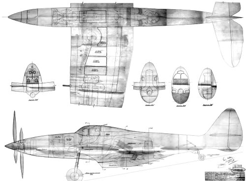
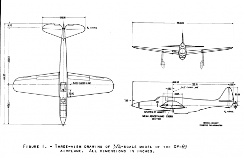
Yes, I covet the kit. The nagging question I have about this version of the XP-69, and yes, I've raised it before, is: what is with the constant-chord center section on the wing? It appears in some drawings of the plane, but not anything I've seen that's contemporary with its development. And what sense does it make? It's constant-chord but not constant thickness. Nor is there a dihedral break, with a horizontal center-section, as in the T-6 Texan or the XP-75.

I just got a copy of Tornado: Wright Aero's Last Liquid-cooled Piston Engine. It's a wonderful reference, and I hope the author can fulfill his stated intention of writing a series of books on experimental engines. It has this nugget re the XP-69:
"One interesting finding of the full-scale tunnel testing...was that the aileron forces were too high. Several solutions were proposed, including an internal sealed balance with wedge trailing edge."

I never heard of a "wedge trailing edge" but maybe that's the origin of the kink in the trailing edge? Doesn't explain the kinked leading edge, though.
[/quote]

My guess is that it's a production joint where two components (wing and fuselage) were to be joined. The break is outboard of most of the wheel well and keeping these big holes in the structure inside the center fuselage would reduce the stress at the joint. Making the wing stub constant chord probably just simplified the fuselage structure.
 
A reminder, on the P-47N, the inboard wing was a constant chord, unlike other P-47 variants.
 

Similar threads

Back
Top Bottom