Republic XF-103 Interceptor

This XF-103 model was made by Al Parker around 1998. Al Parker is a professional model maker, now retired, who worked for Douglas. He also built movie props, including a 20-ft aircraft carrier for the motion picture Tora! Tora! Tora! This XF-103, and others like it, are resin re-casts of an original, factory model. I have a couple of them. It would have been difficult for Gen. Curtis LeMay to write his name on this item, several years after his death.
 
well, 500 bucks for re-cast is a little too high
 
flateric said:
well, 500 bucks for re-cast is a little too high

Yes it is. I paid $275 for mine, and that included a modification of the exhaust nozzle to the square configuration, which I prefer. I guess the extra $225 is for Gen. LeMay's post-mortem autograph. This must have required a time machine which, as we all know, is expensive to operate.
 
I suspected it might not have been genuine, as it just looks too new to be original. Good to have it confirmed.
 
taildragger said:
Just a quibble, but I think your criticism is of concurrent development, not the weapons system concept - which simply (simple to describe anyway) means to develop an entire integrated system from the start.


True. Maybe it would have been more accurate to say "A weakness of the weapon system concept is that it can too easily become a hostage to concurrent-development problems".


The other problem with an "integrated" platform is the potential for making it so integrated that future changes with demands on weight and/or space become difficult to incorporate. This is sometimes not too much of a problem with many aircraft (though it may be more of an issue with a stealth design which is obliged to carry its primary weapons suite internally), but certainly impacts on warships unless they have "space and weight reserved" considerations built in from the start (with all the effects on size, cost, etc. which those precautions entail).
 
What is this in Air Pictorial magazine ?,an early artist impression to republic XF-103 !.
Looks like someone's PSed a picture of a soviet Kh-20 [AS-3 Kangaroo] missile...


cheers,
Robin.
 

Attachments

  • image.png
    image.png
    231.5 KB · Views: 1,928
Manufacturer proposal model of the Republic XF-103 (periscope variant), showing deployed missiles and rocket launch trays.
 

Attachments

  • Republic XF-103 01.jpg
    Republic XF-103 01.jpg
    82 KB · Views: 1,244
Hi,


here is a Model for Republic XF-103.


русские крылья америки
 

Attachments

  • 103.png
    103.png
    230.8 KB · Views: 1,011
Four vendors were awarded periscope research contracts in the first tranche: Bausch & Lomb, Eastman-Kodak, Kollsman and Scanoptics. Five systems were funded for testing; single-refracting ( B&L, Scanoptics ), binocular-refracting and mirror reflecting.

Perhaps because of discoveries during the F-84 test phase in 1958 Chicago Aerial Industries were awarded a contract for investigation into the use of optical fibres in a similar periscope system [ attached ].

Curiously the US Navy continued along their own independent line of research into aircraft periscopes. They planned to install an experimental unit in an A4D, changed their minds to an A3D ( and had designed the installation ) but then cancelled the project when the contractor stated thay they couldn't achieve the required manufacturing tolerances: www.dtic.mil/dtic/tr/fulltext/u2/283115.pdf
 

Attachments

  • CAI_Contract.JPEG
    CAI_Contract.JPEG
    102.3 KB · Views: 761
Hi,

http://archive.aviationweek.com/image/spread/19570909/51/2
 

Attachments

  • 1.png
    1.png
    169.5 KB · Views: 392
Hi fellows,
digging in my files (looking for another matter) I found those drawings of XF-103 that, at glance, appeared to me not already posted. If they are, forgive me...
I think the section with bullet-shaped nose is a first configuration whilst the one with a small dome for periscope was the definitive one. The two other pictures are details of the landing gear as seen on the full scale mock-up.
By the way, I think that the ill-fated F-103 remains a really fascinating plane

Nico
 

Attachments

  • XF-103_early_20160529_0001.jpg
    XF-103_early_20160529_0001.jpg
    382.9 KB · Views: 342
  • XF-103_late_20160529_0002.jpg
    XF-103_late_20160529_0002.jpg
    389.5 KB · Views: 481
  • XF-103 front lg_20160529_0003.jpg
    XF-103 front lg_20160529_0003.jpg
    338.6 KB · Views: 286
  • XF-103 main lg_20160529_0003.jpg
    XF-103 main lg_20160529_0003.jpg
    263.9 KB · Views: 244
___
 

Attachments

  • XF-103 1957.jpg
    XF-103 1957.jpg
    218 KB · Views: 1,120
  • XF-103 1954.jpg
    XF-103 1954.jpg
    212.3 KB · Views: 1,133
  • AP-57 1951.jpg
    AP-57 1951.jpg
    249.3 KB · Views: 1,185
Maybe i'm missing something...but how was the XF-103 supposed to takeoff with the landing gear that far back?
it looks like there's no room to rotate and at any rate the landing gear is way aft of the cg, requiring a lot of download. Was its stance on the landing gear nose high, such that the wing had some angle of incidence even without rotating the body?
 
Someone once said, "if there were a runway that went all the way around the world Republic could build a plane that would use it all". Was in an old book from the 60s or so.
 
I believe it. Anyway, rotation on takeoff seems like the last of Republic's problem with this bird anyway! ;D
BTW, Beizer's story is a gem, i can't get enough oral history straight from the participants' mouth.
 
PaulMM (Overscan) said:
According to former Republic engineer Boriz Beizer, with a hell of a lot of JATO bottles and a prayer or two

;D ;D ;D
 
Hi! I will post each sources later.
(1)Normal wind shield type two side view drawing
(2)Periscope type three side view drawing
(3)Wind tunnel test model.

Up to now, I have not seen a in-depth three side view of this airplane.
Justo-san's following contribution is really surprising!! :eek:

To apply Periscope was USAF's requirement. Fixed type periscope and retractable type periscope were planned.
Also normal shape cockpit was plannd in parallel with periscope type cockpit.
 

Attachments

  • Normal wind shield type.jpg
    Normal wind shield type.jpg
    46.8 KB · Views: 258
  • Periscope type.jpg
    Periscope type.jpg
    43.1 KB · Views: 248
  • WIND TUNNEL TEST MODEL 2 (2).jpg
    WIND TUNNEL TEST MODEL 2 (2).jpg
    148.5 KB · Views: 230
  • WIND TUNNEL TEST MODEL 2 (1).jpg
    WIND TUNNEL TEST MODEL 2 (1).jpg
    71.2 KB · Views: 223
  • periscope concept.jpg
    periscope concept.jpg
    38.5 KB · Views: 246
Last edited by a moderator:
Normal shape cockpit and periscope type cockpit mockup.


Also mockup picture with normal shape cockpit is here.
 

Attachments

  • Normal shape cockpit and retractable periscope type cockpit mockup.jpg
    Normal shape cockpit and retractable periscope type cockpit mockup.jpg
    66.6 KB · Views: 226
https://en.wikipedia.org/wiki/Republic_XF-103
Wikipedia says that....
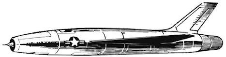
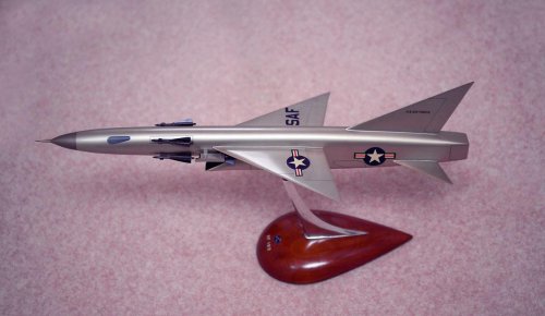
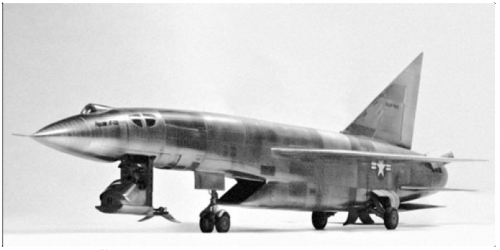
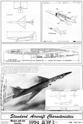
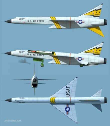
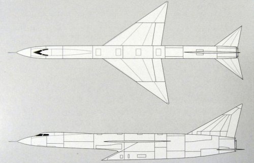
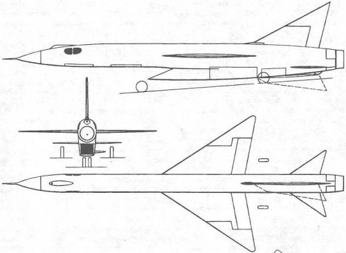
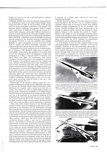
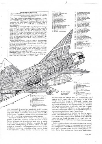
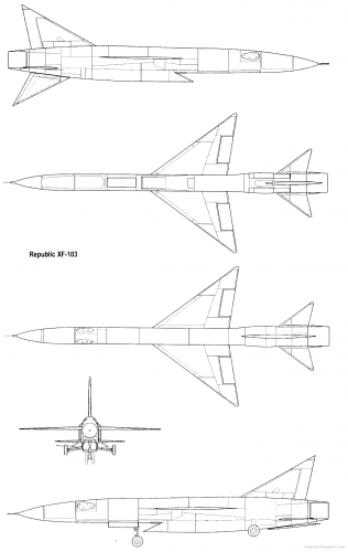
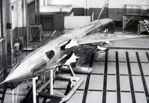
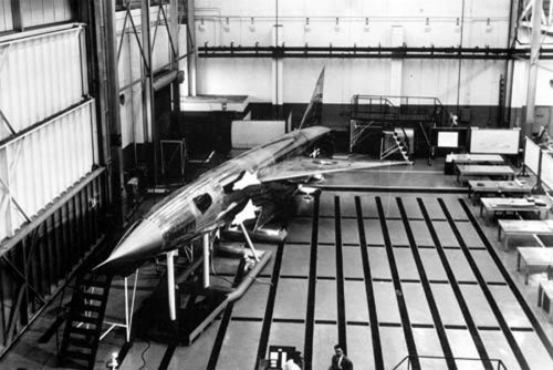
"Wings and control surfaces
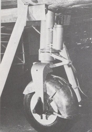
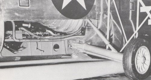
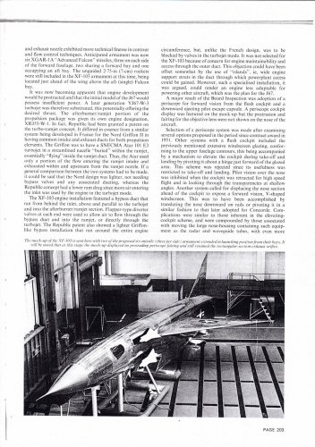
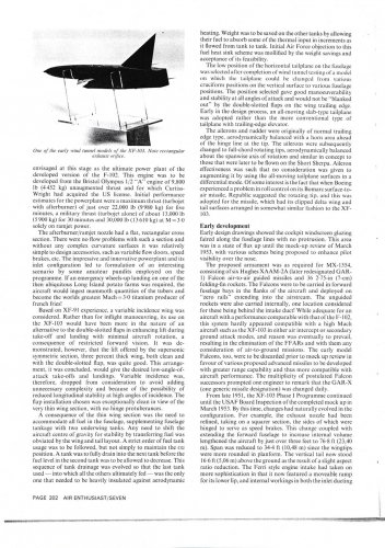
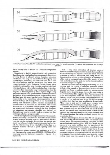
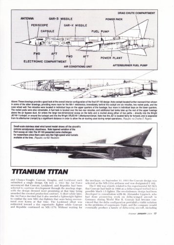
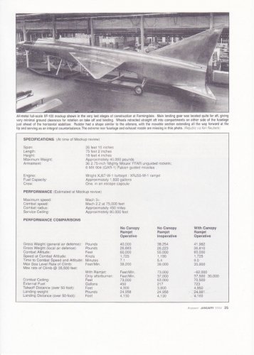
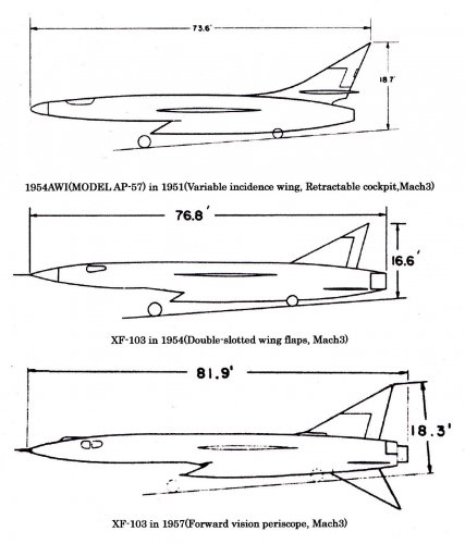
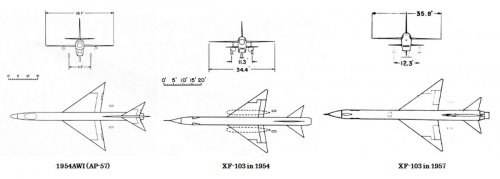
All of the control surfaces were pure delta wings. The main wing was swept at 55 degrees, and could be rotated around the spar to provide variable incidence. For takeoff and landing, the wing was tilted upwards to increase the angle of attack while keeping the fuselage nearly horizontal. The length of the fuselage made it difficult to achieve the same end by tilting the entire aircraft upwards, which would have required a very long extension on the landing gear. The system also allowed the fuselage to fly flat to the airflow at various speeds, setting the trim angle independent of the aircraft as a whole. This decreased trim drag, and thereby improved range.(Is this true? Same as XF-91?)

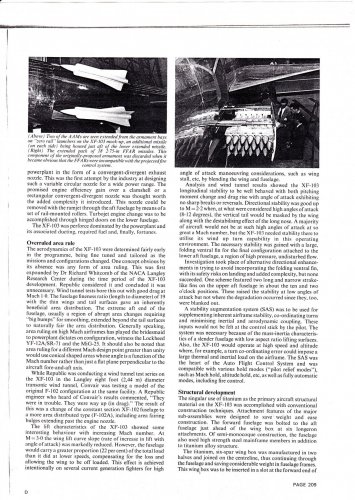
The wing was split at about two-thirds of the span. The portion outside of this line able to rotate independently of the rest of the wing. These movable portions acted as large ailerons, or as Republic called them, tiperons. In order to keep the surface area in front and behind the pivot point somewhat similar, the split line was closer to the fuselage in front of the pivot. Large conventional flaps ran from the fuselage to the tiperons. Hard points for drop tanks were available at about  1⁄3 of the way out from the wing root.

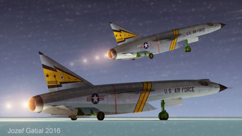
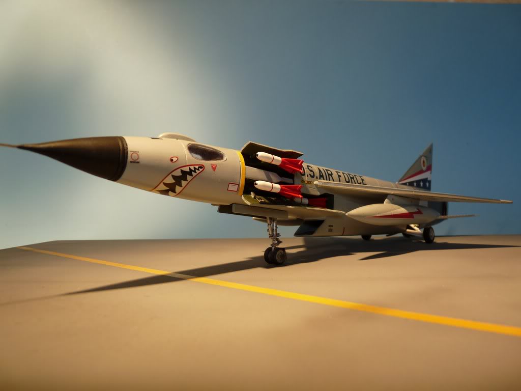
The horizontal stabilizers were seemingly undersized, and mounted below the line of the wing. The larger vertical fin was supplemented by a ventral fin for high-speed stability. This fin folded to the right, as seen from behind, during takeoff and landing to avoid hitting the ground. Two petal-style air brakes were mounted directly behind the horizontal surfaces, opening out and up at about a 45° angle into the gap between the horizontal and vertical surfaces. A provision for a braking parachute is not evident on the mock-up or the various artwork, although this was a common addition for aircraft of the era."
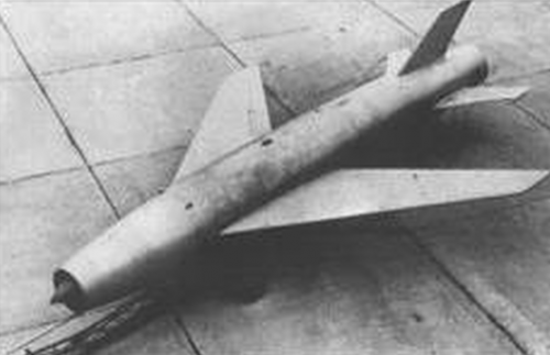
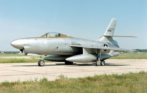
XF-91.
https://en.wikipedia.org/wiki/Republic_XF-91_Thunderceptor
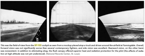
"Another design change was the ability to vary the angle of incidence of the wing as a whole, tilting it up for low speed operations during takeoff and landing, and then "leveling it off" for high-speed flight and cruise. This allowed the fuselage to remain closer to level while landing, greatly improving visibility."
 

Attachments

  • XF-91.JPG
    XF-91.JPG
    306 KB · Views: 542
Hi!
One of the reason why the development of this airplane was canceled is that the development of an engine was difficult at the day.


Engine concept.

Periscope image source.
 

Attachments

  • 1662073_702790883129797_7437272448414100958_n.png
    1662073_702790883129797_7437272448414100958_n.png
    420.4 KB · Views: 272
  • field of view.jpg
    field of view.jpg
    74.2 KB · Views: 1,080
  • cockpit mockup.jpg
    cockpit mockup.jpg
    86.7 KB · Views: 1,317
  • rocket and missile.jpg
    rocket and missile.jpg
    95.7 KB · Views: 1,338
  • air intake and exhaust nozzle.jpg
    air intake and exhaust nozzle.jpg
    92.5 KB · Views: 1,364
  • power plant mockup.jpg
    power plant mockup.jpg
    108.1 KB · Views: 1,411
This cutaway shows round shape exhaust nozzle. But I can't find wing tilt mechanism.

And 1957 round shape exhaust nozzle design. (XF-103 was cancelled in 1957).

1954 square shape exhaust nozzle design.

Wind tunnel test model with round shape exhaust nozzle.(Now I believe this is the final shape of XF-103. Ventral fin is little complicated shape compared with following super drawing by Jozef-san. Wing tip aileron up?)

Jozef-san! How do you think about wing tip aileron and wing tilt mechanism? Or anyone knows about this? Any official document exist?

And video.
View: https://www.youtube.com/watch?v=93wmjQmVPcw
 
Last edited by a moderator:
Hi!
Wikipedia description for XF-103 variable incidence wing is mistake?
 

Attachments

  • page 206.jpg
    page 206.jpg
    529.9 KB · Views: 242
  • page 205.jpg
    page 205.jpg
    433 KB · Views: 198
  • page 204.jpg
    page 204.jpg
    391.5 KB · Views: 190
  • page 203.jpg
    page 203.jpg
    432.4 KB · Views: 191
  • page 202.jpg
    page 202.jpg
    373.6 KB · Views: 180
  • page 201.jpg
    page 201.jpg
    405.3 KB · Views: 173
  • page 200.jpg
    page 200.jpg
    378.4 KB · Views: 180
  • page 199.jpg
    page 199.jpg
    424.7 KB · Views: 196
  • AIR ENTHUSIAST.jpg
    AIR ENTHUSIAST.jpg
    518.3 KB · Views: 234
  • air enthusiast seven.jpg
    air enthusiast seven.jpg
    166.1 KB · Views: 166
Hi!
 

Attachments

  • page 213.jpg
    page 213.jpg
    373.3 KB · Views: 168
  • page 212.jpg
    page 212.jpg
    445.2 KB · Views: 154
  • page 211.jpg
    page 211.jpg
    445.6 KB · Views: 163
  • page 210.jpg
    page 210.jpg
    355.1 KB · Views: 167
  • page 209.jpg
    page 209.jpg
    463.4 KB · Views: 150
  • page 208.jpg
    page 208.jpg
    434.8 KB · Views: 162
  • page 207.jpg
    page 207.jpg
    425.2 KB · Views: 192
 

Attachments

  • republic290XF-103mockup2cockpitvers.jpg
    republic290XF-103mockup2cockpitvers.jpg
    111.5 KB · Views: 179
  • 5700cc1694b30fdb98eb815767294156.jpg
    5700cc1694b30fdb98eb815767294156.jpg
    70.5 KB · Views: 192
  • republic-xf-103-2.png
    republic-xf-103-2.png
    101.1 KB · Views: 221
  • XF-103.JPG
    XF-103.JPG
    50.4 KB · Views: 209
  • XF-103-Proposal-2S.jpg
    XF-103-Proposal-2S.jpg
    90.8 KB · Views: 201
  • early_design_mockup.jpg
    early_design_mockup.jpg
    253.8 KB · Views: 174
  • m11.jpg
    m11.jpg
    64.5 KB · Views: 165
  • HighFlight-XF-103-4.jpg
    HighFlight-XF-103-4.jpg
    195 KB · Views: 158

Attachments

  • page 22.jpg
    page 22.jpg
    278.9 KB · Views: 140
  • page 21.jpg
    page 21.jpg
    289.3 KB · Views: 130
  • page 20.jpg
    page 20.jpg
    283.9 KB · Views: 133
  • page 19.jpg
    page 19.jpg
    281.6 KB · Views: 140
  • page 18.jpg
    page 18.jpg
    396.5 KB · Views: 157
  • page 17.jpg
    page 17.jpg
    287.1 KB · Views: 185
  • page 16.jpg
    page 16.jpg
    299.4 KB · Views: 170
  • page 15.jpg
    page 15.jpg
    272.4 KB · Views: 136
  • page 14.jpg
    page 14.jpg
    265.6 KB · Views: 142
  • 160816201659_Airpower_January_2004.jpg
    160816201659_Airpower_January_2004.jpg
    28.5 KB · Views: 146
Hi!
 

Attachments

  • page 27.jpg
    page 27.jpg
    288.9 KB · Views: 175
  • page 26.jpg
    page 26.jpg
    273.9 KB · Views: 144
  • page 25.jpg
    page 25.jpg
    229.7 KB · Views: 134
  • page 24.jpg
    page 24.jpg
    285.1 KB · Views: 140
  • page 23.jpg
    page 23.jpg
    273.1 KB · Views: 136

Attachments

  • WIND TUNNEL TEST MODEL 2 (2).jpg
    WIND TUNNEL TEST MODEL 2 (2).jpg
    148.5 KB · Views: 148
  • XF-103 FINAL SHAPE.jpg
    XF-103 FINAL SHAPE.jpg
    86.8 KB · Views: 166
  • FINAL SHAPE SIDE VIEW.jpg
    FINAL SHAPE SIDE VIEW.jpg
    57.9 KB · Views: 177
  • FINAL SHAPE THREE SIDE VIEW.jpg
    FINAL SHAPE THREE SIDE VIEW.jpg
    64.2 KB · Views: 163
Last edited by a moderator:
Hi!
XF-103 design in 1954 had no ventral fin.
As a design of this airplane was developed, the area of the vertical tail stabilizer was enlarged one after another.
 

Attachments

  • XF-103_WIND_TUNNEL_TEST_MODEL.jpg
    XF-103_WIND_TUNNEL_TEST_MODEL.jpg
    79.9 KB · Views: 163
  • 060728-F-1234S-076.JPG
    060728-F-1234S-076.JPG
    289.9 KB · Views: 161
  • XF-103_EARLY_WIND_TUNNEL_TEST_MODEL.jpg
    XF-103_EARLY_WIND_TUNNEL_TEST_MODEL.jpg
    254.6 KB · Views: 154

Attachments

  • XF-103 DEVELOPMENT.jpg
    XF-103 DEVELOPMENT.jpg
    176.5 KB · Views: 216
  • XF-103_DEVELOPMENT 2.jpg
    XF-103_DEVELOPMENT 2.jpg
    41 KB · Views: 279

Similar threads

Back
Top Bottom