René Couzinet Projects

Couzinet 70-71 specifications
The aircraft was developed for long-distance postal transport, emphasizing safety, speed and comfort.
safety
In order to guarantee a safe flight even in the event of engine shutdown due to bad weather, the trimotor configuration was the only solution at the day with technology. A single-engine aircraft could not prevent unforeseen situations, no matter how carefully maintained.
Outfitting was considered for ease of maintenance and repair. The engine can be checked even during flight.
speed
The shape of the fuselage was designed for crew’s comfort and to reduce the effects of propeller torque. The wheels were covered with spats. The joint was shaped with a fillet. Restricting the intake air prevented the engine from over revolution. Ground speed was 250km / h. At this high speed, long-distance flights Amenity
Crew members could focus on instrument operation. The seat was easily slidable to ensure the pilot's view. Equipped with a mass balance (or counterweight) for the elevator, eliminating the need for pilot adjustments during cruising. When one of the main wing engines was stopped, a pedal center position adjustment function was provided to eliminate the necessity of rudder pedal counter operation. The windows on the side of the fuselage were sliding to ensure visibility and shut off engine noise. Mail was mounted at the center and rear of the fuselage.
fuselage
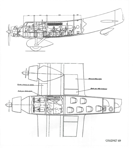
The frame was covered with birch tree skin. The cross section of the fuselage was a square with rounded corners near the cabin, approaching the vertical tail cross section toward the rear. The door, top hatch, and window areas were large. The engine support frame was installed on the first bulkhead, the main wing connection bracket and the control system were installed on the second bulkhead.
The cockpit was installed on the left side and was constructed on a steel pipe frame. The rudder was controlled by a pedal, and the elevator and aileron were controlled by a steering wheel. The operating cord was a rod. The hinge was supported by a ball bearing. The control system could be inspected from the hatch. There were five crew members: pilot, general engineer, second engineer, navigator, and radio.
 
The electrical system is as follows.
・ A 600 watt, 24 volt generator is mounted on the wing engine one by one.
・ Link table x 2
・ Control panel
・ 40 amp capacity battery
・Landing lights × 2. Adjust on the ground
・ Signal light × 2
・ Navigation light × 3
・ Indoor light, cargo room lighting, wing engine instrument lighting, instrument panel lighting
Wing
The main wing is a low wing with a total width of 30m. The spar has two 810 × 231.5mm sections. The skin of the wing is birch plywood. The dihedral angle is +1 degree. Aileron is 0.50m thick x 6.60m long.
Equipped with trim tab. The chord length is 4.50 m on the fuselage side and 2.20 m on the wing tip side. The radius of the leading edge of the wing is 2.85m, and the radius of the trailing edge is 7.30m. The total wing area is 97.560m2, of which the effective area is 90m2.
The wing loading is 165kg / m2 at takeoff. The aspect ratio is 9.25, and the wing thickness ratio is 22 at the root and 16 at the aileron end.
Within the wing leading edge is an access passage to the engine.
There are five fuel tanks in each of the left and right wings. The capacities are 1,235, 1,100, 957, 800 and 610 liters from the fuselage side. The three wing tip fuel tanks are equipped with emergency discharge pipes. Three emergency fuel discharge tubes protrude from the lower surface of the wing.
There is an 880 liter fuel tank in the center of the wing in the fuselage. These eleven fuel tanks are interconnected and pumped to a 678-liter reservoir below the wing engine.
The landing lights on the lower left and right wings are each equipped with a semi-recessed landing light. There is also a hatch for lighting ammunition.
engine
This aircraft was equipped with three Hispano-Suiza 12Nb .
The Hispanosuiza 12Nb engine has a nominal output of 650 horsepower. The engine is a V-type 12 cylinder, bank angle 60 degrees, water-cooled. Bore x stroke = 150mm x 170mm, total displacement 36 liters.
The inner wall of the cylinder is nitrided, and the mirror finish prevents wear of the piston. The engine compression ratio is 6.2 and the fuel used is grade 74 octane. Carburetor is Solex 56MOV.
In the airworthiness certification inspection, the output of the engine was 762 hp / 2,200 rpm for emergency output, 745 hp for lift-off power, and 650 hp for nominal output / 1,800 rpm. Maintained 460 horsepower at 4,000m altitude.
The engine alone weighs 470 kg (excluding the reduction gear and supercharger), and the cruise output is 520 hp.
At the end of 1933, Hispano Suiza installed a reduction gear (reduction ratio 1/2) and changed the model name to 12Nbr. The number of propellers was four.
The engine support frame is made of steel pipe.
The engine-related instruments on the cockpit dashboard are as follows.
・ Tachometer
・ Hydraulic gauge
・ Water temperature gauge
・ Oil temperature gauge
・ Fuel pressure gauge
The instruments of the engineer's dashboard are as follows.
・ Tachometer
・ Hydraulic gauge
・ Fuel pressure gauge
Use compressed air to start the engine. Lubricating oil is pumped from the central tank to the reservoir of each engine.
The engine cowling is easily removable. The cowling on the front is removable without removing the propeller. The engine cowling is fixed to the engine support via a silent block.
The engineer opens and closes the shutter on the front of the radiator according to the water temperature. The propeller is made of Chovière-type metal.
Fire measures
A manual fire extinguisher is installed indoors.
Landing gear
The main tires are made of Messier and have a size of 1,630 x 365 mm. The tail wheel tire is made of Messier and have a size of 673 x 216mm. The tail wheel can be turned on the ground and returned in the aircraft axis direction by a rubber band. The main wheels are equipped with a brake, which is braked by a lever on the right side of the cockpit. By changing the distribution of the left and right braking forces, it is possible to change the direction during taxiing.
 
Last edited:
Disadvantages of Arc-en-Ciel
By the standards at the time, the lift-drag ratio and weight of this aircraft were comparable to those of long-distance competition airplanes. Compared to the DC3 of the same period (twin-engine, 1,000 horsepower x 2), the Arc-en-Ciel was 3 tons heavier and had no landing flaps, albeit at the same total power. (I imagine taking off and landing was not so easy.)
Since the all engines of this aircraft rotated in the same direction, the effects of engine torque could not be corrected at low speeds.
The wings was for competition aircraft rather than transport aircraft. Lack of stability due to lack of dihedral angle. The upper surface of the wing was parallel to the ground, and the dihedral was caused by a change in the cross section of the wing.
 Time was spent on countermeasures against control surface buffeting and tail wing vibration. Vibration occurred at 170 km / h, especially at landing and when one engine stopped.
The vibration stopped when the throttle was throttled. At first, a cable was attached to the tail to take measures. The cause of the vibration was considered to be the aerodynamic problem of the engine cowling. For this reason, the aircraft for Air France changed the cowling shape.
The distance between the main wing and the tail, the mounting position, the distance between the trailing edge, the fillet, etc. were adjusted to take measures.
Test flight results conclusion:
1. Reducing the spacing between the wings and tails reduces buffeting but reduces stability. The vibration then recurred when the horizontal stabilizer area was increased.
2. Adding a fillet to the wing root had the same effect as reducing the distance between the wing and tail. Experience shows that the distance between the trailing edge of the main wing and the leading edge of the horizontal tail is 1 / 1.1. In other words, in the case of this aircraft with the root chord length of 4.50 m, this distance is 5 m. At the same time, the center of gravity was advanced by 34 to 24% to increase stability. For this purpose, the wing engine was advanced by 0.60 m and the fuselage engine was advanced by 0.30 m. Due to the shortening of the fuselage, the cross section of the fuselage has also changed. As a result, the area of the rear end of the fuselage corresponding to the vertical tail was reduced, so an auxiliary vertical tail was added. Another option was to consider implanting the rear fuselage of Couzinet60. This plan, called the Arc-en-Ciel No. 9, was never implemented.
To investigate the effect of the fillet, a 1/2 scale flight model Couzinet22 was created.


Attachments

  • Couzinet_20_Annuaire_de_L'Aéronautique_1931.jpg
    Couzinet_20_Annuaire_de_L'Aéronautique_1931.jpg
    109.1 KB · Views: 87
From Aviation magazine 1964,

here is a family of RC.110 to RC.113,and a 3-view to RC.111 Project.
 

Attachments

  • 111.png
    111.png
    245.9 KB · Views: 65
  • 110-113.png
    110-113.png
    419.8 KB · Views: 60
From Aviation magazine 1965,

here is a Couzinet RC.130s.
 

Attachments

  • 130.png
    130.png
    449.9 KB · Views: 44
From Icare 1957,

here is an small Info about 500-ton flying boat Project of 1937 ?;

Already then - early 1937 - and among many minor projects, some of which are currently underway abroad, Couzinet
had outlined before us the outline of a 500-ton seaplane the sketches of which he had in his boxes, a veritable flying
liner that could not be conceived, he said smiling, moved by motors with pistons.

For this precursor, it was a system propulsion with turbines whose application already seemed most precise to his
mind.

It is not difficult to move a heavier than air, he suggested: all you need is a little skill; and with a number
suitable for anyone horsepower can rob a cathedral. But art,that is to say the design of the drawing, then the
making the spacecraft is something else.
 

Attachments

  • a.png
    a.png
    58.3 KB · Views: 34
  • b.png
    b.png
    513.6 KB · Views: 51
From Ailes 1936,

here is a Couzinet RC.90 bomber mock-up.
 

Attachments

  • 2.png
    2.png
    687.2 KB · Views: 52
  • 3.png
    3.png
    941.7 KB · Views: 67
From Icare 198.
 

Attachments

  • 1.png
    1.png
    72.1 KB · Views: 54
  • 2.png
    2.png
    72.3 KB · Views: 52
  • 3.png
    3.png
    69.9 KB · Views: 59
  • 4.png
    4.png
    471.4 KB · Views: 55
  • 5.png
    5.png
    110.1 KB · Views: 60
Hi,

does anyone know a good article from Gallica site about Air-Couzinet
AC.20 bomber of 1937/39.
 
From Docavia No.9.
 

Attachments

  • 1.png
    1.png
    1 MB · Views: 28
  • 2.png
    2.png
    1.4 MB · Views: 34
From, AEROMEDN45
 

Attachments

  • 30.png
    30.png
    584 KB · Views: 13
  • 31.png
    31.png
    625.4 KB · Views: 14
  • 32.png
    32.png
    482.7 KB · Views: 12
  • 33.png
    33.png
    634.1 KB · Views: 11
  • 34.png
    34.png
    290.6 KB · Views: 12
  • 35.png
    35.png
    422.7 KB · Views: 11
  • 36.png
    36.png
    491.6 KB · Views: 11
  • 37.png
    37.png
    457.2 KB · Views: 12

Similar threads

Back
Top Bottom