Possible DARPA/USAF Combined Cycle Demonstrator (CCD) from Boeing

flateric

ACCESS: USAP
Staff member
Top Contributor
Senior Member
Joined
1 April 2006
Messages
10,701
Reaction score
6,567
Possible clues to Boeing possible entry in possible DARPA/USAF program called Combined Cycle Demonstrator (CCD)

DARPA and the U.S. Air Force are currently
considering a program that could
provide such a need and focus, Orton said.
The program, called the Combined Cycle
Demonstrator, would involve the design
of a hypersonic aircraft that could take off
from the ground, fly to a speed of Mach 7,
then fly back to Earth and make a powered
landing.
“If this program (the CCD) were to get
going, I think that could be a tremendous
shot in the arm for future aircraft as well as
for space access,” Orton said.
DARPA and the Air Force have not issued
a go-ahead for such a program yet,
Orton said. “But the technology work
we’re doing now with the Air Force, NASA
and DARPA is laying the groundwork for a
program like that,” he said.

Interesting if this would be a Boeing contender to HTV-3X, and if HTV-3X related to CCD?
http://www.boeing.com/news/frontiers/archive/2008/feb/feb08frontiers.pdf
 

Attachments

  • boe-hyp-08-1.jpg
    boe-hyp-08-1.jpg
    77.2 KB · Views: 531
  • boe-hyp-08-2.jpg
    boe-hyp-08-2.jpg
    25.7 KB · Views: 510
How exactly does this combined cycle work? Does it work better than current designs in terms of overall specific impulse, and thrust-to-weight ratio?

Assuming it's not classified?


KJ_Lesnick
 
That's it I'm sending the black helicopters to pick you up. You know just way to much about our nefarious plans.

-MIB


::)
 
Well, it's not like I know anything that's classified. All that I said was publically acknowledged.

KJ Lesnick
 
Good spotting, Flateric...

Boeing and NorthGrum are not sitting on their hands and waiting for LockMart to win BlackSwift by default.

KJ... There are two or three technologies at work here that make these different from earlier hypersonics. One is the high-speed jet technology that came out of IHPTET and allows jet engines to run efficiently to much higher speeds, with much higher specific thrust (lb thrust per lb airflow) than the SR engine. Another (related) is the use of non-cryogen liquid hydrocarbons heated and cracked over a catalyst to fuel a scramjet. Another is the inward-turning SCRJ inlet, which is round, as God intended pressurized tubes to be.

Blackswift patent: http://appft1.uspto.gov/netacgi/nph-Parser?Sect1=PTO2&Sect2=HITOFF&p=1&u=%2Fnetahtml%2FPTO%2Fsearch-bool.html&r=1&f=G&l=50&co1=AND&d=PG01&s1=elvin&s2=hypersonic&OS=elvin+AND+hypersonic&RS=elvin+AND+hypersonic

NorthGrum: http://www.aviationweek.com/aw/blogs/defense/index.jsp?plckController=Blog&plckScript=blogScript&plckElementId=blogDest&plckBlogPage=BlogViewPost&plckPostId=Blog%3a27ec4a53-dcc8-42d0-bd3a-01329aef79a7Post%3a67b24244-d902-4b43-83e3-071ba30738b9
 

Attachments

  • Blackswift Patent 3.jpg
    Blackswift Patent 3.jpg
    40.5 KB · Views: 422
TBCC test rig from recent NASA papers with strikingly familiar intakes...
http://www.aiaa.org/pdf/conferences/hypersonics06nasa.pdf
 

Attachments

  • TBCC_a.jpg
    TBCC_a.jpg
    132.9 KB · Views: 527
LowObservable said:
Another (related) is the use of non-cryogen liquid hydrocarbons heated and cracked over a catalyst to fuel a scramjet.

Turning cerosene into H2 - that's exactly what current Leninets/AJAX guy tried to explain to Strike Force interviewer (seems with little success).
 
LowObservable said:
Blackswift patent: http://appft1.uspto.gov/netacgi/nph-Parser?Sect1=PTO2&Sect2=HITOFF&p=1&u=%2Fnetahtml%2FPTO%2Fsearch-bool.html&r=1&f=G&l=50&co1=AND&d=PG01&s1=elvin&s2=hypersonic&OS=elvin+AND+hypersonic&RS=elvin+AND+hypersonic
Not exactly. That's the Lockheed Falcon Hypersonic Cruise vehicle... a B-52-sized robotic bomber.
 

Attachments

  • falconhcv.jpg
    falconhcv.jpg
    13.5 KB · Views: 412
BTW, I got a nickname for Boeing stuff...it associates strongly with sturgeon for me with these pronounced intakes...
 
Orionblamblam said:
That's the Lockheed Falcon Hypersonic Cruise vehicle... a B-52-sized robotic bomber.

Little tiny birdy...
 

Attachments

  • HCV_BUFF.jpg
    HCV_BUFF.jpg
    9.9 KB · Views: 169
flateric said:
LowObservable said:
Another (related) is the use of non-cryogen liquid hydrocarbons heated and cracked over a catalyst to fuel a scramjet.

Turning cerosene into H2 - that's exactly what current Leninets/AJAX guy tried to explain to Strike Force interviewer (seems with little success).

You mean like JP-7 (as on the X-43) or MCH?
 
Phantom Works CCD inlet configuration variants
 

Attachments

  • Boeing ITI-2.jpg
    Boeing ITI-2.jpg
    13.3 KB · Views: 733
  • Boeing ITI-1.jpg
    Boeing ITI-1.jpg
    26.2 KB · Views: 743
  • boeinghyp.jpg
    boeinghyp.jpg
    47.4 KB · Views: 261
KJ_Lesnick said:
flateric said:
LowObservable said:
Another (related) is the use of non-cryogen liquid hydrocarbons heated and cracked over a catalyst to fuel a scramjet.

Turning cerosene into H2 - that's exactly what current Leninets/AJAX guy tried to explain to Strike Force interviewer (seems with little success).

You mean like JP-7 (as on the X-43) or MCH?

The X-43 used hydrogen.
 
Inlets are updated 3D inward compression Busemann (Billig, Molder, Kothari) type require no ramps. Streamline traced sugar scoop type off design bleed. This is beyond the now dated 2D Aurora and X-43 design tech. TBCC is turbine based combined cycle propulsion.
 
I know the inlet is more efficient, but does it manage to aid compression-lift as well (or better) as the 2D-ramp design does (just curious because the duct doesn't seem as long or occupy as much of the vehicle's surface area, though I could be wrong...)?

KJ_Lesnick
 
The primary purpose of an inlet for an airbreathing propulsion system is to capture and compress air for
processing by the remaining portions of the engine. In achieving this objective, the inlet design must provide for
a minimum weight geometry that enables an efficient compression process, generates low drag, produces nearly
uniform flow entering the combustor, and provides these characteristics over a wide range of flight and engine
operating conditions.

The design of hypersonic inlets is complicated by the many constraints, both aerodynamic and
mechanical, such as starting limits, boundary layer separation limits, constraints on combustor entrance flow
profiles, leading edge radii limits, variable geometry flexibility, and cooling system constraints.

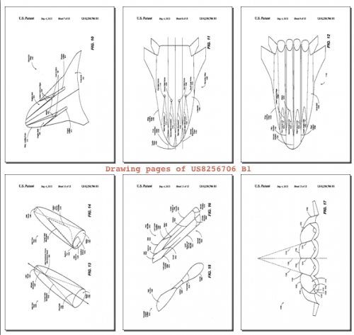
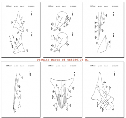
A wide variety of inlet shapes have been explored <...> [including] inlets derived
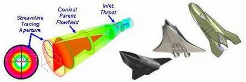
from streamtubes traced from known parent flowfields. Starting with a known or easily calculated
flowfield, such as the Busemann inlet (=conically symmetric internal compression supersonic inlet), 3D inlets can be derived by tracing streamlines in the parent flowfield and connecting the streamlines to create a streamtube. Using solid walls to encase the streamtube, a 3D inlet shape results that has the same inviscid inlet flowfield and performance characteristics as the parent flowfield.

Tracing three-dimensional inlet shapes from known flowfields has long served as the basis for a powerful inlet
design methodology. If the parent flowfield has high performance, the resulting 3D inlet will likely retain the high performance
characteristics. Further, streamline-traced inlets can often be designed with highly swept leading
edges, which can be beneficial from heat transfer and drag standpoints. Finally, the streamline tracing can be done
in a manner where the resulting inlets are much better suited to self-starting compared the parent flowfield.


The initial interest in inward-turning engine concepts dates to the late 1950s in the United States. <...> the advantage of the inward turning engine concepts are a lower wetted surface area per unit massflow process by the engine. This feature inherently leads to lighter structures, lower heat loads and less frictional losses within the propulsion system.

The disadvantages of the concept include the difficulty associated with incorporation of variable geometry, which leads to challenges associated with starting the engine when high contraction ratios are desired, and the inherent three-dimensional nature of the flowfield, which leads to a requirement for detailed 3D analyses at off-design conditions.

One of the first propulsion systems developed using the streamline tracing of an inward-turning inlet was the
SCRAM missile concept developed by the Johns Hopkins University Applied Physics Laboratory in the early
1960s through the mid 1970s. Development of this modular engine and its successful operation at Mach 5-7.2
speeds validated for the first time the streamline tracing design technique as applied to a scramjet engine.

Interest in inward turning inlet concepts was maintained through the 1990s by small teams of researchers
examining the performance benefits of the concept. Examples of these efforts are the works of Molder4, Kothari5,
and Billig6,7. These analytical works continued to explore the advantages of inward-turning scramjet engine
concepts and their use in novel configuration development.

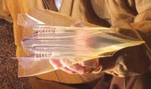
The Hypersonic Collaborative Australian-U.S. Experiment (HyCAUSE) used these studies as a springboard for
investigation of inward turning scramjet engine concepts8. Within the HyCAUSE program, and inward turning
engine was developed using an inlet design derived from streamline tracing. The inlets were designed for full
capture at Mach 10 operation, and the engine cross-sectional shape was selected to be elliptical based on a desire to
maintain structural efficiency while minimizing the dimension of the combustor cross-section. This inlet geometry
served as the basis for both ground and flight tests.

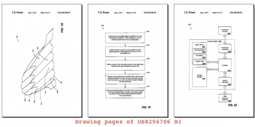
The streamline tracing technique has been proven to be a powerful design tool for hypersonic inlets, but there are
a number of limitations of conventional streamline-traced designs. When streamline tracing in a parent flowfield that
has uniform inflow and outflow conditions, the resulting inlet must contain the same cross-sectional shape in both
the freestream and at the inlet throat. For example, a rectangular freestream cross-section will have a rectangular
cross-section at the inlet throat and just as a circular free-stream profile will be circular at the throat. Often, one is
interested in designing an inlet with different cross-sectional shapes in the freestream and inlet throat to aid in the
integration of the engine in an airframe. Thus, it is of current interest to develop methodology to morph different
streamline traced designs so that the cross-section of the inlet will go through a shape change. Therefore, it is
necessary to understand the implications of blending streamline traced designs on inlet performance and the extent
to which the flow can be transitioned between two different streamline traced designs before dramatic losses are
incurred.

Performance Analysis of Hypersonic Shape-Changing Inlets Derived from Morphing Streamline Traced Flowpaths
Trent M. Taylor and David VanWie
Johns Hopkins University Applied Physics Laboratory, Laurel, MD, 20723
 
Does this design produce better takeoff and landing characteristics over a 2D waverider? (I can't find anything on google)

Kendra Lesnick
 
"Does this design produce better takeoff and landing characteristics over a 2D waverider?"

I think this produces better takeoff and landing characteristics over a 2D waverider...
 

Attachments

  • breeze.jpg
    breeze.jpg
    2.3 KB · Views: 611
LO, you made my day! ;D
 
LowObservable said:
"Does this design produce better takeoff and landing characteristics over a 2D waverider?"

I think this produces better takeoff and landing characteristics over a 2D waverider...

In other words, about the same as your average Republic Aviation aircraft. :p
 
http://www.dtic.mil/dtic/tr/fulltext/u2/a535837.pdf

The Boeing report did not mention HTV-3, but mentioned a Technology Experimental Vehicle (TX-V) and a Manta 2025. I posted a pic of the Manta 2025.

I tried searching for the TX-V on the forum, but didn't find anything. Was this part of HTV-3, a follow on program, something else entirely?
 

Attachments

  • Manta2025.jpg
    Manta2025.jpg
    22.1 KB · Views: 1,108
very good start at the forum, bunch of thanks!
 
jjnodice said:
I tried searching for the TX-V on the forum, but didn't find anything. Was this part of HTV-3, a follow on program, something else entirely?

It was Boeing's design for an HTV-3X/Blackswift:
http://www.aviationweek.com/aw/blogs/defense/index.jsp?plckController=Blog&plckScript=blogscript&plckElementId=blogDest&plckBlogPage=BlogViewPost&plckPostId=Blog%3A27ec4a53-dcc8-42d0-bd3a-01329aef79a7Post%3A40e634bd-e162-4c2a-b852-bd9c6b65f79f
 
More than meet the eyes... A recently released Boeing patent (US8256706) discusses "Integrated hypersonic inlet design". It clearly relates to design strategies empowered by Phantom Works leads on their Blackswift contender. Abstract: "Methods, aircraft, and engine nacelles are disclosed. A wing leading edge of a planform is superimposed on a wing shockwave that extends in a first direction from a shockwave apex toward the wing leading edge. A waverider shape is streamline traced between the wing leading edge and a trailing edge of the planform to form a waverider wing. A position of an engine inlet vertex relative to the waverider wing is identified. An inlet shockwave is projected from the inlet vertex in a second direction generally opposed to the first direction. The inlet shockwave intersects the wing shockwave. An inlet leading edge of an engine inlet includes a lower leading edge including a plurality of points where the inlet shockwave intersects the wing shockwave."


Thumbnails of illustrations attached...
 

Attachments

  • US8256706-Batch01.png
    US8256706-Batch01.png
    80.4 KB · Views: 781
  • US8256706-Batch02.png
    US8256706-Batch02.png
    40.6 KB · Views: 723
  • US8256706-Batch03.png
    US8256706-Batch03.png
    70.8 KB · Views: 696
jjnodice said:
The Boeing report did not mention HTV-3, but mentioned a Technology Experimental Vehicle (TX-V) and a Manta 2025. I posted a pic of the Manta 2025.

I tried searching for the TX-V on the forum, but didn't find anything. Was this part of HTV-3, a follow on program, something else entirely?

Manta I know has been an internal Boeing project for some time, probably predating HTV-3 as a formal program. In the lifting bodies thread there is a photo from a Boeing publication that shows a model of it. I am not sure if TX-V is based on the same design or not, but I may have some material that would clear that up.

http://www.aviationweek.com/Blogs.aspx?plckBlogId=Blog:27ec4a53-dcc8-42d0-bd3a-01329aef79a7&plckController=Blog&plckScript=blogscript&plckElementId=blogDest&plckBlogPage=BlogViewPost&plckPostId=Blog%253A27ec4a53-dcc8-42d0-bd3a-01329aef79a7Post%253A40e634bd-e162-4c2a-b852-bd9c6b65f79f
 
One of those patent thumbnails reminds me of Republic's Aerospaceplane concept from the 60's.
 
DSE said:
This one?

That's the Boeing publication which shows two models, somewhere I have some of the sources of the figures in:
http://www.google.com/patents/US20090313968
I don't know that I could post them even if I can find them though
 
Back
Top Bottom