Hi Bill,
Hm, I've got to admit that I have no idea what you mean, perhaps because I don't recognize the abbreviation "CR".
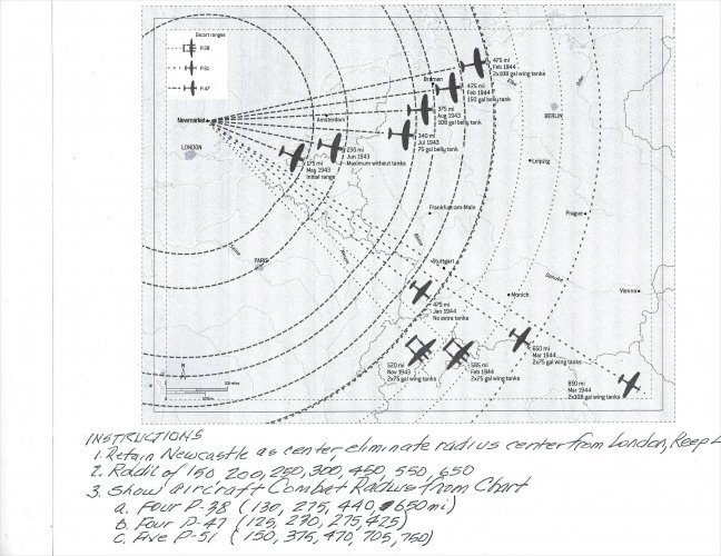
Excellent input, I've eliminated the post-D-Day claims and split up the 1944 data at the mid-March point:

Regards,
Henning (HohUn)
Suggestion - note that the 'point of origin is ~ 52degrees for East Anglia. The CR would originate 2degrees above Schweinfurt.
Hm, I've got to admit that I have no idea what you mean, perhaps because I don't recognize the abbreviation "CR".
Second note - plots before D-Day when P-47 operating on 305gal internal fuel, or before mid March when 2x10⁸gal capability arrived could be revealing.
Third note - D-Day screws context up when 9th AF P-47s arrive on the continent and continuously east.
Excellent input, I've eliminated the post-D-Day claims and split up the 1944 data at the mid-March point:

Regards,
Henning (HohUn)

") Centered on Wattisham, as before.
Centered on Wattisham, as before.