

You are using an out of date browser. It may not display this or other websites correctly.
You should upgrade or use an alternative browser.
You should upgrade or use an alternative browser.
Northrop Grumman B-21 Raider (LRS-B)
- Thread starter TomS
- Start date
Scott Kenny
ACCESS: USAP
- Joined
- 15 May 2023
- Messages
- 19,668
- Reaction score
- 28,152
Because the B-21 is explicitly stated as being able to carry one MOP, and MOPs are 21.5ft long. So the B-21's single bay is at least as long as one B-2 bay.How do we know for a fact that the B-21
Bay is not smaller than B-2 or have equal carrying capacity? If anything, given that we do actually know for a fact that B-21 is smaller than a B-2 (132ft span va 172ft span), I’d wager that the B-21 have less carrying capacity than a B-21 and likely less total weapons bay volume as well.
If the bay is 25 ft long, it would be just long enough to rack 3x GBU-38s in tandem. (GBU-38s are 8ft0.6in long)
Because the B-21 is explicitly stated as being able to carry one MOP, and MOPs are 21.5ft long. So the B-21's single bay is at least as long as one B-2 bay.
Not that I disagree with idea it likely carries GBU-57, but has any official source actually stated that?

Forest Green
ACCESS: USAP
- Joined
- 11 June 2019
- Messages
- 14,596
- Reaction score
- 31,707
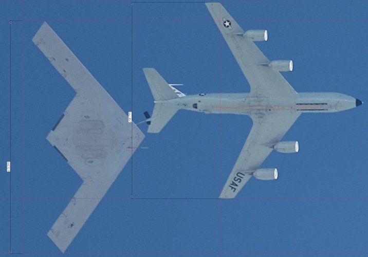
You're assuming the B-21 is at same altitude as tanker, but it sits lower, hence nearer to camera, so no valid measurement is possible, since objects in foreground will be bigger relative to background. So if you measured 47.7m from that, it's definitely smaller than that.This probably has much higher resolution (much less quantization error when detecting wing tips)... My measurements give 47.7 meters (156.5 feet). No idea where the 150 feet lower bound estimate comes from...
Attachments
Well if you want an error analysis… The maximum length of the KC-135 boom is 48 feet (14.6 meters), so even if we assume the boom is fully extended and completely vertical (the worst, worst case scenario), at a maximum wingspan error of 1% (about half a meter) , the altitude must be lower than 4800 feet, which is way, way lower than any regular aerial refueling operations (typically occur at 15-25k feet).but it sits lower, hence nearer to camera, so no valid measurement is possible
Point being, given the length of the boom and the typical altitude of aerial refueling operations, the error created by the bomber and the tanker being at different altitudes would be minimal (much less than half a meter). So co-altitude would be a reasonable approximation.

- Joined
- 1 April 2006
- Messages
- 12,285
- Reaction score
- 15,110
Forest Green
ACCESS: USAP
- Joined
- 11 June 2019
- Messages
- 14,596
- Reaction score
- 31,707
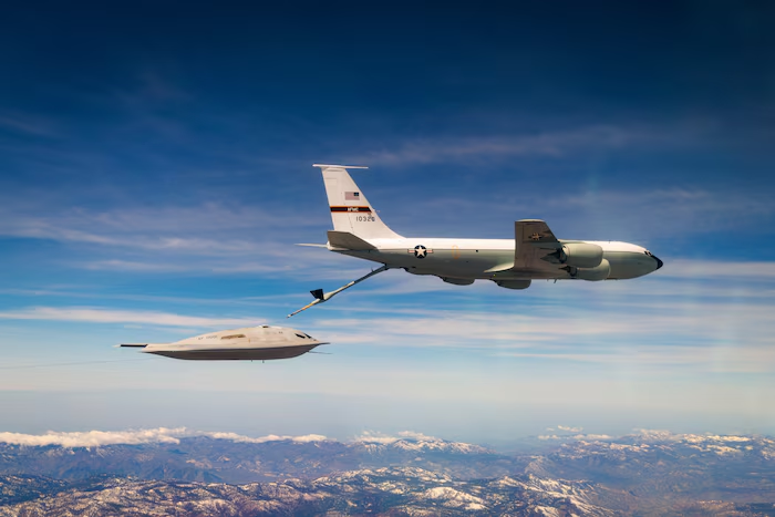
Is the camera is on the ground though. To me it looks to be on another plane below at who knows what altitude difference, and it isn't directly below either, so you've got parallax. At the typical refuelling altitude of 20+kft, I doubt an image that good could be produced from the ground, maybe I'm wrong.Well if you want an error analysis… The maximum length of the KC-135 boom is 48 feet (14.6 meters), so even if we assume the boom is fully extended and completely vertical (the worst, worst case scenario), at a maximum wingspan error of 1% (about half a meter) , the altitude must be lower than 4800 feet, which is way, way lower than any regular aerial refueling operations (typically occur at 15-25k feet).
Point being, given the length of the boom and the typical altitude of aerial refueling operations, the error created by the bomber and the tanker being at different altitudes would be minimal (much less than half a meter). So co-altitude would be a reasonable approximation.
The satellite on the other hand is a few hundred km or more up, so the difference in distance to the plane vs ground is negligible.
BTW, is that a KC-135, wingspan 39.88m?
- Joined
- 1 April 2006
- Messages
- 12,285
- Reaction score
- 15,110
View: https://www.instagram.com/reel/DXKIRJNCTq2/At the typical refuelling altitude of 20+kft, I doubt an image that good could be produced from the ground, maybe I'm wrong.
View: https://www.instagram.com/p/DWHQLKVkYKy/
Attachments

Last edited:
Forest Green
ACCESS: USAP
- Joined
- 11 June 2019
- Messages
- 14,596
- Reaction score
- 31,707
So it can be but was it in the case in question? We know the other image is a satellite shot. There's also the side-on angle which doesn't help.
Interesting... From what I measured the horizontal stabilizer span in that image is 13.1m, which is slightly longer than what I measured from a three-view drawing (12.9m). Note that KC-135R/T enlarged the stabilizer from the previous models to work with the larger engines, so using an earlier model would result in a stabilizer span of ~12m.@JoshuaH you can notice that at this angle stabilizer span is meter shorter than it should be for accurate planform projection for given wingspan so this view really can play tricks.
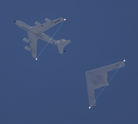
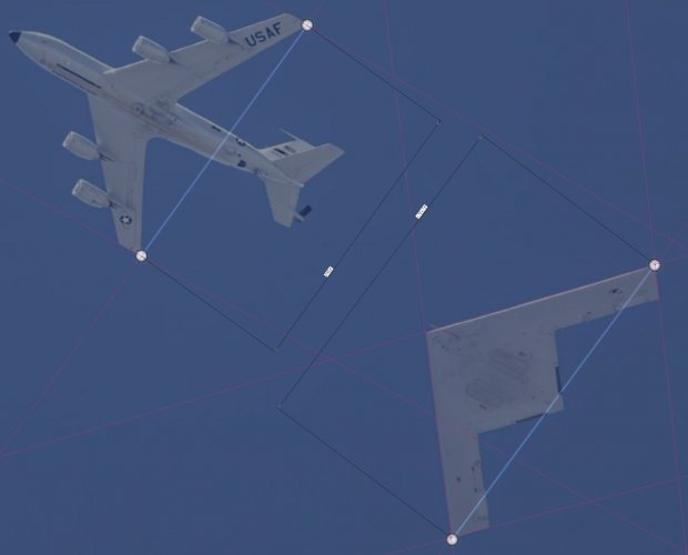
The image we were talking about was not official. It was taken by minor_triad at View: https://x.com/minor_triad/status/2031458425910211068?s=46&t=GCOWdLMxS0F7wZALYgkBzgIs the camera is on the ground though. To me it looks to be on another plane below at who knows what altitude difference, and it isn't directly below either, so you've got parallax. At the typical refuelling altitude of 20+kft, I doubt an image that good could be produced from the ground, maybe I'm wrong.
.
So it is overwhelmingly likely taken from the ground.
For the parallax concern... Sure, then let's use an image that has to be taken from the ground: the picture that mojaveairvisuals took (the same person who took the videos flateric posted). In this case the KC-135 is slightly closer to the camera compared with the B-21, so any parallax underestimates the wingspan of the B-21 and overestimates the wingspan of the KC-135. In this case I measured a wingspan of 47.98 meters. I believe any difference in locating the actual wing tips in the photographs produce much more error than parallax at this point... Which is also why I consider the satellite photo as a less reliable source, not because of the image itself, but because it is really hard to accurately locate the wing tips at that resolution...
Yes...?BTW, is that a KC-135, wingspan 39.88m?
Attachments
- Joined
- 1 April 2006
- Messages
- 12,285
- Reaction score
- 15,110
Aha. This explains everything.Note that KC-135R/T enlarged the stabilizer from the previous models to work with the larger engines, so using an earlier model would result in a stabilizer span of ~12m.

GreenBullet
International rules-based hors d'oeuvre
- Joined
- 2 September 2015
- Messages
- 71
- Reaction score
- 131
That's within a rounding error of exactly 157 feet, which kind of supports the estimate, as it's weirdly coincidental that a poor estimate would be so close to a whole number. I'm convinced 157 is it.47.85 m
GreenBullet
International rules-based hors d'oeuvre
- Joined
- 2 September 2015
- Messages
- 71
- Reaction score
- 131
It doesn't mean nothing. But I do agree there's certainly no requirement for a whole number, historically. We shall see.
Forest Green
ACCESS: USAP
- Joined
- 11 June 2019
- Messages
- 14,596
- Reaction score
- 31,707
How large is the actual body of a B-21 relative to a B-2? Also, if the span is smaller but the length is the same, that seems to imply more sweep??
I measured 18.8 meters, shorter than the B-2. The sweep seems to be slightly larger than the B-2, at around 35 degrees.How large is the actual body of a B-21 relative to a B-2? Also, if the span is smaller but the length is the same, that seems to imply more sweep??
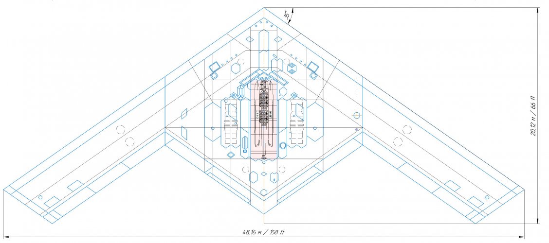
How large is the actual body of a B-21 relative to a B-2? Also, if the span is smaller but the length is the same, that seems to imply more sweep??
The length is almost equal because the B-21 adopted a single diamond back tail instead of the saw tooth (change made to B-2 to allow low altitude penetration flight as future proofing).
- Joined
- 1 April 2006
- Messages
- 12,285
- Reaction score
- 15,110
13208 mm. still specific Stratotanker lenght is often a quizInteresting... From what I measured the horizontal stabilizer span in that image is 13.1m, which is slightly longer than what I measured from a three-view drawing (12.9m). Note that KC-135R/T enlarged the stabilizer from the previous models to work with the larger engines, so using an earlier model would result in a stabilizer span of ~12m.
Attachments
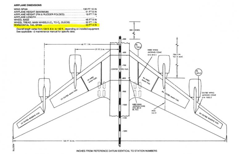
Well we are measuring different things for length: I was measuring “length of body”, as Forest Green asked. As of wingspan, the difference is small enough I consider it confirming instead of ruling over my estimations.It seems you missed everything
Forest Green
ACCESS: USAP
- Joined
- 11 June 2019
- Messages
- 14,596
- Reaction score
- 31,707
Yeah, I sort of asked two questions which produced a mislead for the second question. The length is measured from the front to the rearward-most point, which is the rearward-most point of the wing. What's interesting is that I managed to measure an accurate length from the satellite shot but the wingspan I measured seems to be a good way off the aerial measurements. But then, in the satellite shot the wing actually looks thicker on one side of the aircraft.Well we are measuring different things for length: I was measuring “length of body”, as Forest Green asked. As of wingspan, the difference is small enough I consider it confirming instead of ruling over my estimations.
- Joined
- 1 April 2006
- Messages
- 12,285
- Reaction score
- 15,110
Because you have used some weird ways for this.but the wingspan I measured seems to be a good way off the aerial measurements.
Forest Green
ACCESS: USAP
- Joined
- 11 June 2019
- Messages
- 14,596
- Reaction score
- 31,707
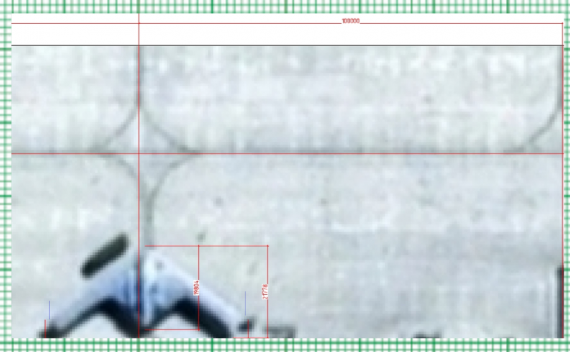
You mean maths? All I did was measure how many squares the 100m was, divide by that number and multiply by the number taken by B-21.Because you have used some weird ways for this.
(100/57.5 small squares) x 26.5-27.0 small squares = 46.1-46.96m (slightly different this time).
Measuring to blue lines, which is where it looks like edges are to me. The right side is very difficult to assess but even adding an extra 0.5 small squares I still get less than 47m. To really push the envelope of interpretation, if I take the 100m as 57 small squares (which it's clearly over) and then use 27 small squares for the aircraft, then I get 47.37m. But that really stretches it beyond the maximum of reality. 100m is clearly over 57 small squares and the aircraft is clearly under 27 small squares, even going right to the red line on the right. Not really sure where the red line on the left came from, because there's clearly a gap there to me, whereas the right side is a little fudgy.
Attachments
Last edited:
- Joined
- 1 April 2006
- Messages
- 12,285
- Reaction score
- 15,110
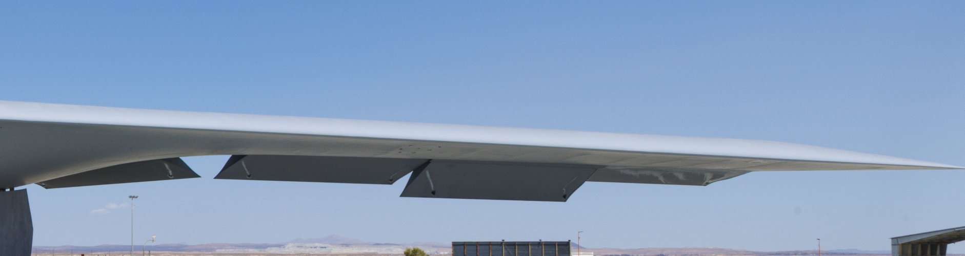
a miracle!But then, in the satellite shot the wing actually looks thicker on one side of the aircraft.
Attachments
Forest Green
ACCESS: USAP
- Joined
- 11 June 2019
- Messages
- 14,596
- Reaction score
- 31,707
From directly over head and with the sun pointing left and back, that should have made the opposite (left) wing look thicker, not the right.
- Joined
- 1 April 2006
- Messages
- 12,285
- Reaction score
- 15,110
But.. it has. LE has distinct anhedral just like outer wing tips.B-21 had some wing twist, the B-2 does not.
Attachments
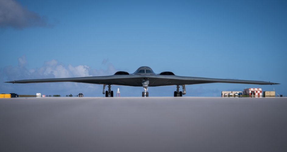
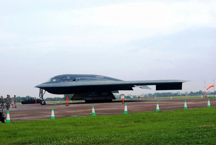
Attachments

FighterJock
ACCESS: Above Top Secret
- Joined
- 29 October 2007
- Messages
- 7,256
- Reaction score
- 8,571
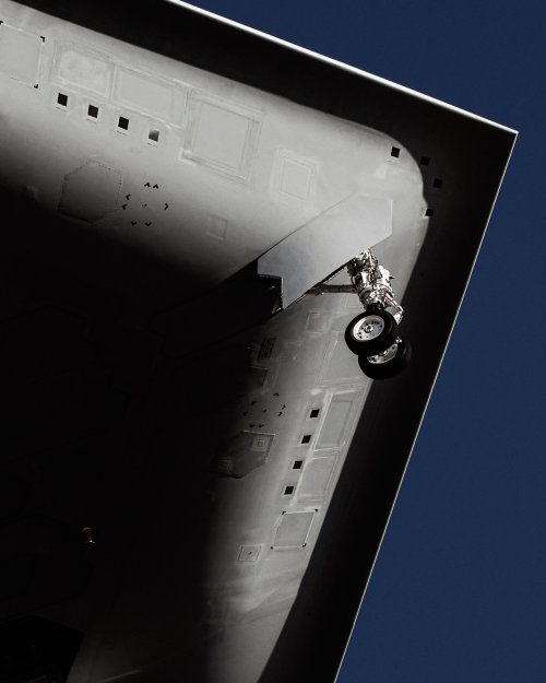
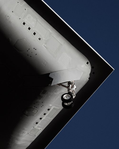
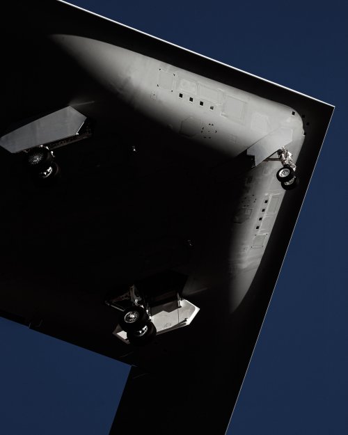
These are the closest images that we have to date of the B-21's fuselage, thanks Raptor82. 
Scott Kenny
ACCESS: USAP
- Joined
- 15 May 2023
- Messages
- 19,668
- Reaction score
- 28,152
That hook at the leading edge of the wing is very interesting to me...T-2:
- Joined
- 28 January 2008
- Messages
- 1,669
- Reaction score
- 4,263
A new method of attenuation compliments of the X-47B and other programs, evolution SK my friend.That hook at the leading edge of the wing is very interesting to me...
Scott Kenny
ACCESS: USAP
- Joined
- 15 May 2023
- Messages
- 19,668
- Reaction score
- 28,152
Makes a very interesting airfoil shape.A new method of attenuation compliments of the X-47B and other programs, evolution SK my friend.

dark sidius
ACCESS: Top Secret
- Joined
- 1 August 2008
- Messages
- 1,634
- Reaction score
- 1,736
I don't understand what is so interesting ? It is a question I am not a Aerodynamic expertMakes a very interesting airfoil shape.
NUSNA_Moebius
I really should change my personal text
- Joined
- 26 May 2012
- Messages
- 256
- Reaction score
- 169
Seems like an evolution of the B-2’s leading edge. Always took notice of the Spirit’s “beak”.
Your original post that I replied to could be misleadingly read as carrying same total capacity of JDAMs as B-2 instead of same capacity of JDAM per bay. If it is per bay then yeah, it makes sense for it to have the same capacity (both volumetric and weight) as B-2 but B-21 having only 1 bay. This tracks with B-21’s smaller wing span and double instead of quad bogie landing gears.Because the B-21 is explicitly stated as being able to carry one MOP, and MOPs are 21.5ft long. So the B-21's single bay is at least as long as one B-2 bay.
If the bay is 25 ft long, it would be just long enough to rack 3x GBU-38s in tandem. (GBU-38s are 8ft0.6in long)
Kerburettor
ACCESS: Restricted
- Joined
- 8 February 2021
- Messages
- 9
- Reaction score
- 35
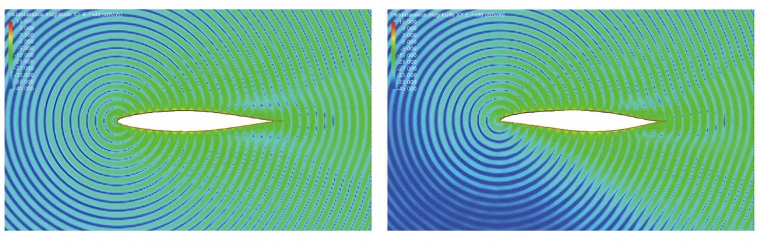
It's a compromise between stealth and aerodynamics. Basically, a hooked and sharp leading edge tends to reduce wave scattering, especially ahead and below the airfoil, where it really matters when it comes to the position of the scanning radar in relation to the aircraft.I don't understand what is so interesting ? It is a question I am not a Aerodynamic expert
The chinese have produced simulations to illustrate this (for example: Han et al. "On airfoil research and development: history, current status, and future directions", 2021)
However, this poses aerodynamic problems at incidence since this kind of sharp and flat leading edges (flat along the suction side that is...) tends to favor flow separation since pressure recovery doesn't happen smoothly just aft a sharp LE (or a flat plate for that matter if you want a caricature).
Likewise, the aerodynamicists at Northrop noticed during the B2's development that having a sharp leading edge made the problem worse for swept wings since swept wings naturally produce more spanwise flow the more swept and tapered they are: a sharp LE makes for very sharp acceleration peaks as the LE-normal flow component turns around the LE towards the suction side and then is subject to very strong adverse pressure gradients which considerably weaken it against the spanwise component (which results in more crossflow than useful lift-producing flow). As a consequence, when operating at incidence or low speeds in hot/high T-O conditions, a swept flying wing with a sharp LE will have very little authority and dangerously approach departure.
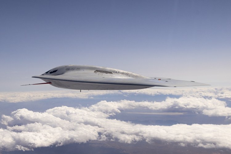
Part of the solution is to modify the sharpness of the leading edge where it matters: Make it very sharp at the nose of the aircraft and at the wingtips where EM waves will focus and scatter. This way you can control the direction of scattering (see the EM simulation pictures above). Prefer a rounder leading edge elsewhere along the span to better control the aerodynamic behavior of the aircraft. This is very obvious from a side-on view:
The other part of the solution is to make the LE hooked downwards as mentioned earlier in the thread. People also call this a hawkbill LE. The genius of the solution lies in many aspects:
- you can design the round hook such that it naturally points downwards in the direction of the flow such that for a wide range of incidences, the flow will follow the hook and be subject to a more gentle pressure recovery aft the curve of the LE than if it were sharp. To be more technical, the hook behaves like the deployed slat of a conventional wing (which will tend to align with the effective direction of the disturbed flow). And you can get away with making this round LE a bit more sharp without a huge penalty in aerodynamic performance.
- a hawkbill LE makes the pressure distribution more front-loaded, which usually gets neutral pitching moment (Cm~0). This helps to not having to force the aft portion of the airfoil to produce negative lift in order to produce a pitch up moment.
- in transonic flight, a sharp leading edge would produce a strong acceleration as the flow turns around the LE, it then keeps accelerating til it happily and very soon becomes supersonic and you end up with a shock which produces lots of drag and a loss of lift if the shock sits too far upstream. A gentle hawkbill spreads out the acceleration profile using a more progressive curvature throughout, which delays recompression and allows you to alleviate wave drag or have the shock sit where you want it to be.
Attachments
Last edited by a moderator:

- Joined
- 28 October 2019
- Messages
- 77
- Reaction score
- 328
Northrop came up with the "toothpick" designation. John Cashen tells the story on pages 63 to 66 of this interview with Peter Westwick.I've seen the B-2's leading edge described as "toothpick shape
Attachments
- Joined
- 1 April 2006
- Messages
- 12,285
- Reaction score
- 15,110

