
You are using an out of date browser. It may not display this or other websites correctly.
You should upgrade or use an alternative browser.
You should upgrade or use an alternative browser.
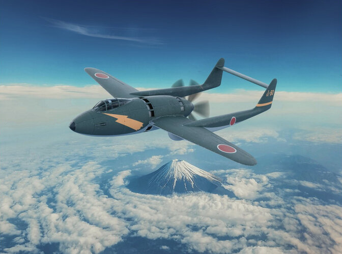
Mitsubishi J4M Senden ''Luke'' pusher fighter
- Thread starter Vietcong
- Start date
blackkite
Don't laugh, don't cry, don't even curse, but.....
- Joined
- 31 May 2007
- Messages
- 8,822
- Reaction score
- 7,729
Hi!
This video include some important information.
I will list up them near future.
View: https://www.youtube.com/watch?v=DO37yHlvIsE
This video include some important information.
I will list up them near future.
- Mitsubishi J4M Senden
Early in 1942 the Kaigun Koku Hombu issued the 17-shi-Otsu specification calling for a high-performance, land-based interceptor to supersede the Raiden.
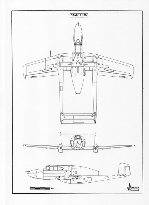
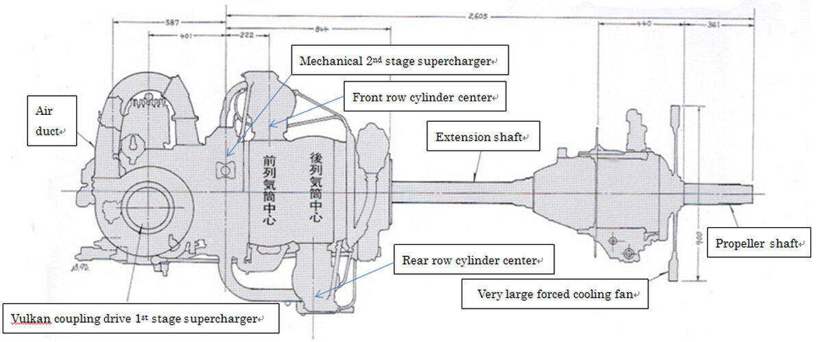
The Kawanishi firm proposed the K-90/J3K project, a first version of the Jinpu with Nakajima Homare engine. Mitsubishi submitted the M-70/J4M Senden, a twin-boom airframe powered by one 2,130 hp MK9D (Ha-43-42) supercharged engine, with Vulkan coupling and forced cooling fan, driving a six-bladed pusher propeller. It was like the North American Vultee XP-54 and Swedish SAAB J-21, equipped with tricycle landing gear.
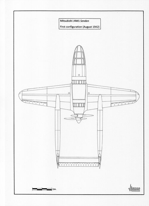
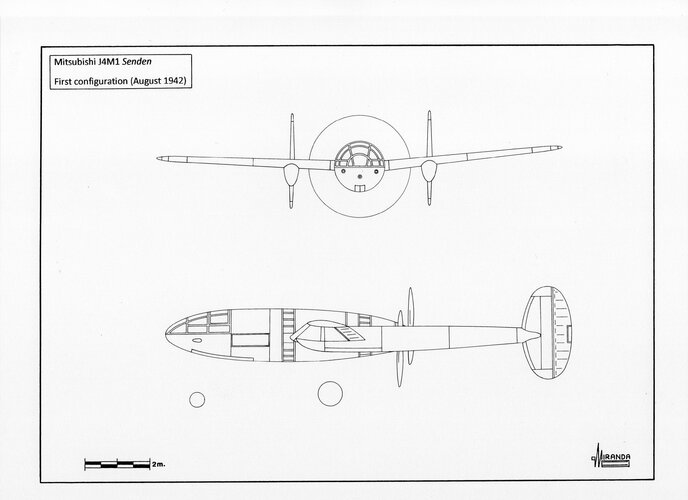
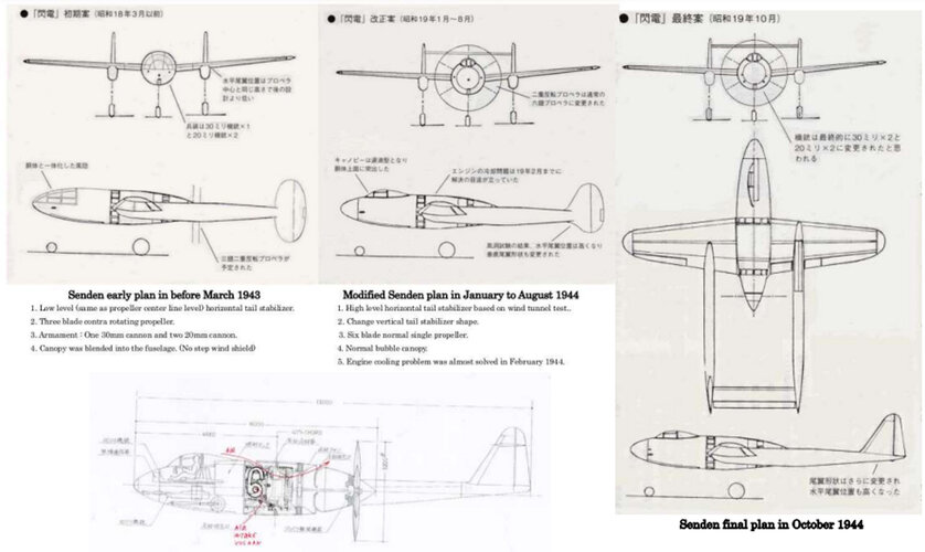
In August 1942 Mitsubishi started the wind tunnel tests with a wooden model provided with three-bladed contra-rotating propellers. This first design, called J4M1, would be armed with a Type 5, 30 mm cannon mounted on the nose leg and two Type 99, 20 mm cannons located to both sides. The two tailfins were oval-shaped like those of the Lockheed P-38.
J4M1 technical data
Wingspan: 12.5 m, length: 12.5 m, wing area: 24.7 sq.m.
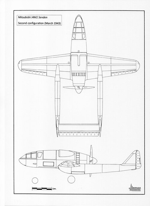
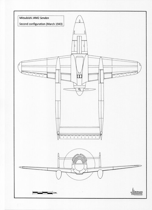
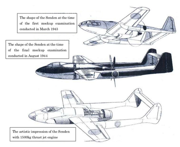
The IJN considered that the engine cooling system was insufficient and in the next version (J4M2 March 1943) two dorsal air intakes and one ventral were installed. This version was called ‘Plan-A’ and had triangular tailfins and a modified windshield. The counter-rotating propellers were replaced by a four-bladed, constant-speed propeller with 3.2 m of diameter and breakaway mechanism to allow the pilot bail-out.
J4M2 technical data
Wingspan: 12.5 m, length: 12.5 m, wing area: 22 sq.m, max weight: 4,886 kg.
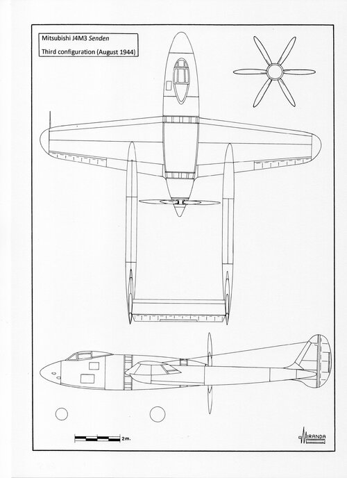
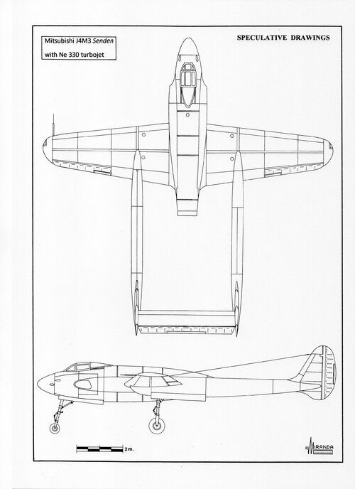
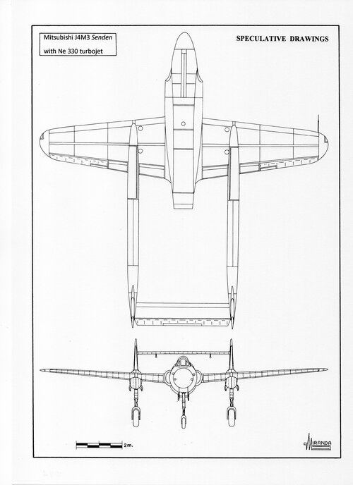
The J4M2 wind tunnel tests showed hard vibration of tail horizontal stabilizer, which was replaced by a smaller surface area located in an elevated position to avoid compressibility problems. In March 1943 the J4M3 mock-up was ready for the Kaigun Koku Hombu inspection. The new design, called ‘Plan-B’, had evolved aerodynamically to compensate for the excessive drag generated by the high tailplane.
The windshield design was changed to bubble canopy and the air-scoops were replaced by eight suction inlets. The tailfins had more rounded shapes and the armament was increased to four cannons. It was proposed to replace the propeller with a Sumitomo six-bladed, constant-speed propeller with 3.2 m of diameter.
J4M3 technical data
Wingspan: 12.5 m, length: 13 m, wing area: 22 sq.m, max weight: 4,400 kg.
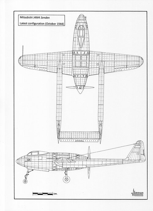
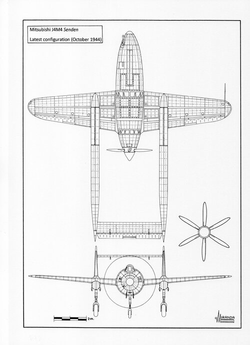
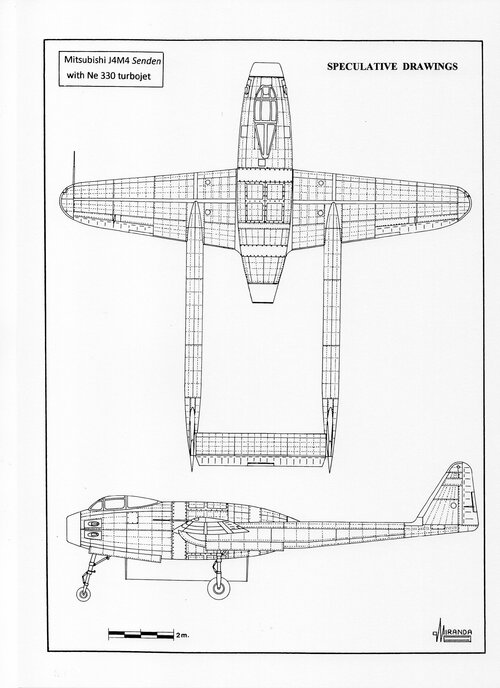
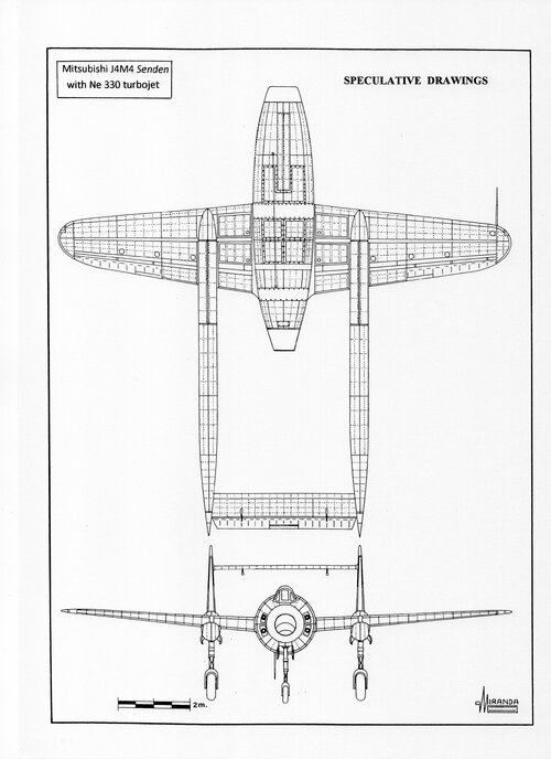
The J4M4 was the definitive version, with triangular tailfins and three cannons, proposed to Kaigun Koku Hombu in October 1944, but the Senden was cancelled shortly after, due to the failure of the Vulkan coupling development and excessive vibrations in the extended shaft.
J4M4 technical data
Wingspan: 12.5 m, length: 13 m, wing area: 22 sq.m, max weight: 5,260 kg, max speed: 703 kph, service ceiling: 12,000 m.
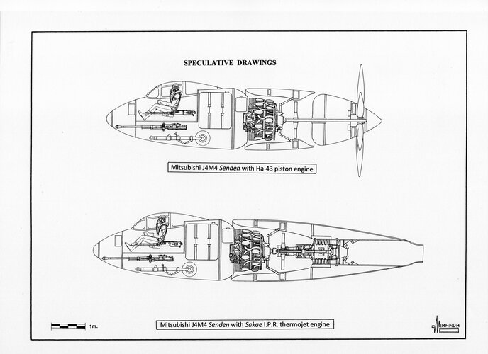
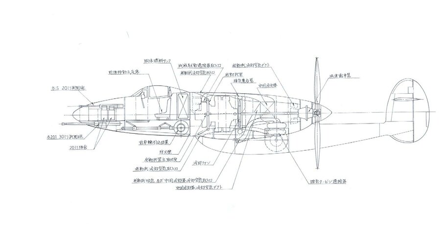
To circumvent the numerous problems caused by the engine, Mitsubishi considered using the Sakae I.P.R. a Campini thermojet with 600-740 kgf static thrust. This type of powerplant consisted of a 920 hp Nakajima Sakae 11 radial engine driving a five-stage axial compressor at 5,280 r.p.m.
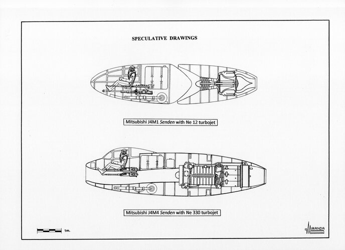
The compressed air was mixed with 74 octane sprayed fuel in a 2.43 m length chamber combustion, burning at 1,000 degree centigrade before being ejected by an exhaust nozzle at 350 m/s. Unofficial drawings have been published depicting a J4M1 powered by a Yokosuka Ne 12 (TR 30) centrifugal turbojet, a J4M3 and a J4M4 with Kugisho Ne 330 axial turbojets.
The Swedes came to the same conclusion and in 1947 replaced the Daimler-Benz 605 piston engine of the SAAB J-21 with a D.H. Goblin centrifugal turbojet.
Attachments
blackkite
Don't laugh, don't cry, don't even curse, but.....
- Joined
- 31 May 2007
- Messages
- 8,822
- Reaction score
- 7,729
blackkite
Don't laugh, don't cry, don't even curse, but.....
- Joined
- 31 May 2007
- Messages
- 8,822
- Reaction score
- 7,729
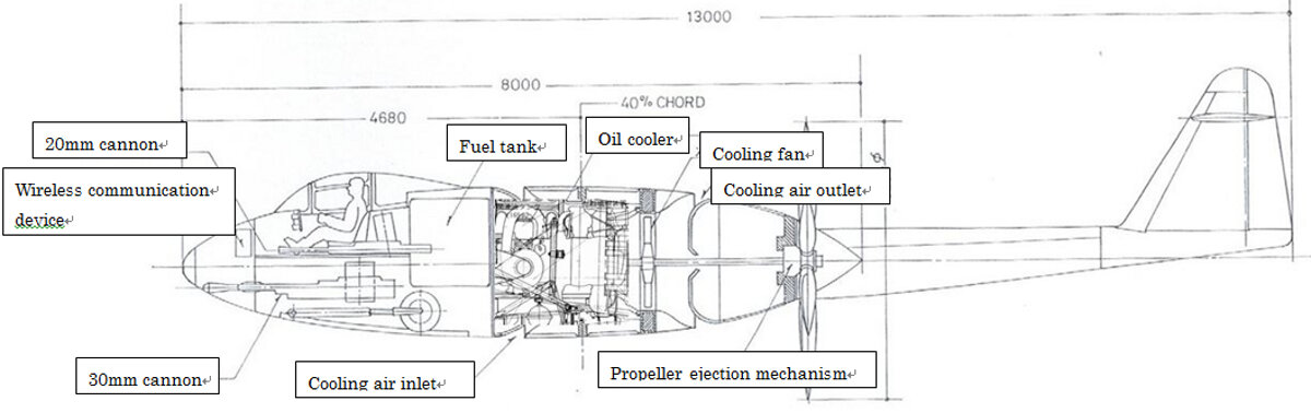
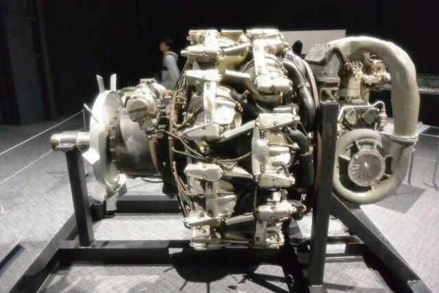
Mitsubishi completed a cooling test fuselage in August 1943 to check the performance of the engine cooling system. The cooling test fuselage was equipped with an actual Ha-43 engine, a forced cooling fan, a oil cooler, and a propeller, and was tested under various operating conditions.
Due to the interference between the engine air intake and the main wing, it was difficult to evenly flow the engine cooling air throughout the engine, but this problem was solved by installing a guide plate by a trial-and-error method.
In order to ensure engine cooling performance, the shape and size of the forced cooling fan were optimized by a trial-and-error method, and by February 1944, an engine cooling system capable of ensuring sufficient cooling performance was completed.
Attachments
Scott Kenny
ACCESS: USAP
- Joined
- 15 May 2023
- Messages
- 11,737
- Reaction score
- 14,524
I'd be very suspicious of getting enough airflow without scoop inlets, especially once the plane got moving.
More people should have an allergy to lawyers...The good news is that my fear of airplane crashes has been replaced by an allergy to lawyers.
blackkite
Don't laugh, don't cry, don't even curse, but.....
- Joined
- 31 May 2007
- Messages
- 8,822
- Reaction score
- 7,729
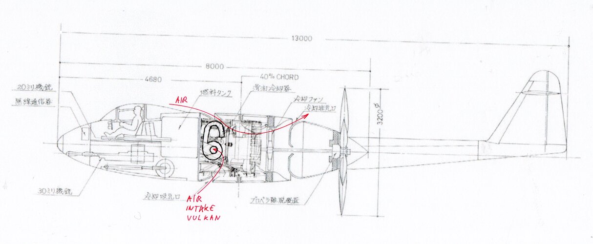
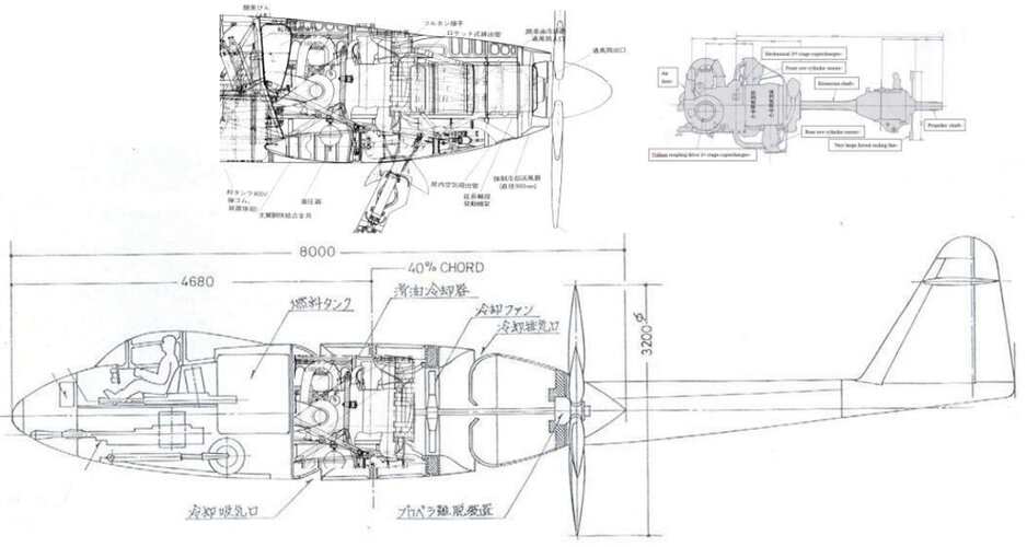
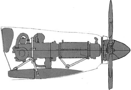
Hi! Propulsion system of Shinden(top) and Senden(bottom).
Senden's system is a speculation.
What was the shape of the engine reduction mechanism and the forced cooling fan of the Senden fighter?
Senden's engine : Mitsubishi HA43-41(MK9D)
Shinden's engine : Mitsubishi HA43-42(Modified MK9D), Take off power 2,130hp
Senden's system is a speculation.
What was the shape of the engine reduction mechanism and the forced cooling fan of the Senden fighter?
Senden's engine : Mitsubishi HA43-41(MK9D)
Shinden's engine : Mitsubishi HA43-42(Modified MK9D), Take off power 2,130hp
Attachments
Last edited:
Similar threads
-
 Japanese Secret Projects:Experimental Aircraft of the IJA & IJN 1939-1945
- Started by Pelzig
- Replies: 261
-
Mitsubishi J4M1 derivatives /Japanese text
- Started by Tophe
- Replies: 3
-

-

-