MiG-29 Avionics

What would be a computer too weak to do this? How do you quantify or know the needed computations for N-019?
 
BZPP-4D allows for radial closures of 1200kmh
BZPP-4 allows CC Radar locks of beyond 10km

What would be a computer too weak to do this? How do you quantify or know the needed computations for N-019?

Again, this is still WIP research, but a contrary theory to a no radial limit is:

The target speed range of −2200 to +1100 km/h in “Tail-on” (Догон) mode was may be limited by the radar’s digital processing system, rather than by what the radar could physically measure. The radar’s analogue tracking system is capable of detecting higher speeds, but the digital system used a 15-bit fixed-point format that imposed limits.

There are three possible reasons why the software may have these imposed limits:

- Resolution vs. speed range: The digital system represented values between −1.0 and +1.0. Increasing the maximum speed would require a larger scaling factor, meaning each digital step would represent a larger change in speed and reduce accuracy. Limiting the target speed to +1100 km/h allowed the system to use a smaller scale, giving a resolution of roughly 0.067 km/h per step. This would help with accurately tracking and filtering small changes caused by noise.
- Preventing overflow: If a value exceeded the limits of the 15-bit format, the binary value could overflow and wrap around, potentially turning a large positive number into a negative one. The software likely kept the speed within a safe range to prevent this kind of sign error, which could cause serious problems in later calculations.
- Closure-rate calculations: The radar needs to calculate the relative or closure speed between the fighter and the target. By restricting the target's allowable speed range, the software could ensure that subtracting the two velocities stayed within the numerical limits of the system. This avoided overflow and reduced the need for additional error-handling in the guidance and tracking calculations.

Again, these are educated guesses since documentation is not available, however signed 15bit should be enough for +2500/-2500kmh and no manual mentions limitations in Lock mode, only in search, so most likely it doesnt have limits, but there are always other possibilties.
 
Idk how we can say x number of bits is enough to have no radial speed limits but I’m not a radar math person either. Su-27 uses C100, it can track through notch in over 3° lookup under 30 km range.And its manuals don’t even mention speed limitations in search mode except that target must be over 180-200 kmh.

The C100 is also not the only computer for radar. The radar is its own analog-digital computer that does things on its own. The C100 is merely an “executive” device sending out “flags” of different kinds to different devices depending on read conditions changing. I would bet the radar is basically doing all the target finding and processing, the C100 is telling radar to turn on, switch to this mode and this position, oh you found targets here I’ll display it for the pilot on HUD. Send flag to go into lock mode. Pilot presses break lock send flag to return to search and reset.
That kinda stuff. I’ve heard this from others who looked much deeper into MiG-29 then I such as “Kosh.” So It’s not my own assumption, but reading MiG-29B it makes perfect sense
 
Last edited:
reading MiG-29B it makes perfect sense
The information I talked about is from the MiG-29B, and also I prefixed this entire conversation with the fact that these are all educational guesses. There might as well be no constraints in lock mode. Also I love how we were able to change your mind about the radial speed limit, you used to be so hard set on the idea that it did now you defend it so much :), nice to see people can change their minds...
 
I don’t ever remember being set against it. I gladly conversed with the first people who brought it up to see why they thought this and posted a bug report on ED forums within 24 hrs. Please, you consistently mistake my caution and waiting to get all the facts I reasonably can for things that are far more sinister, when they aren’t! But whatever. You learn patience and caution with time.

I may have seemed to be “against it” when someone randomly says “I’m pretty sure it’s doesn’t have these limits” out of the blue, which is why I listened to his explanation.
No one should be changing their mind on a moments notice from stranger input, even if you want it to be true or it “makes sense”.

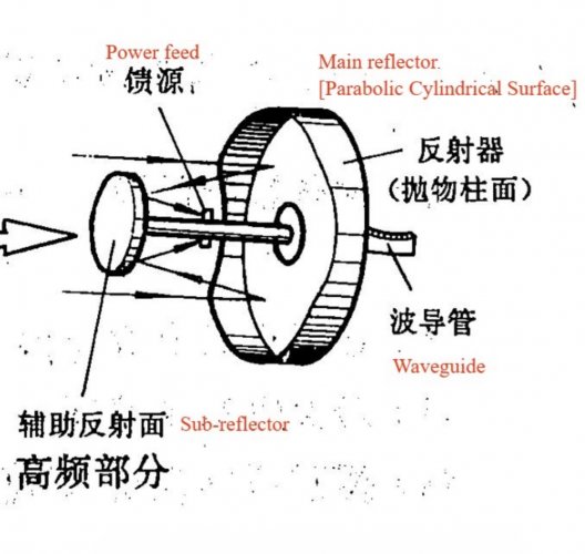
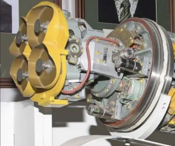
R-27R antenna is 4 mini cassegrains in one.,
 

Attachments

  • IMG_6746.jpeg
    IMG_6746.jpeg
    161.2 KB · Views: 7
  • IMG_6823.jpeg
    IMG_6823.jpeg
    64.6 KB · Views: 4
Last edited:
If anyone here has documentation on the Ts100 in detail, and the firmware, I'd really appreciate it! Thank you!
Look at the topic related to soviet vs western computer comparison. There was some block diagrams from hardware point of view. I doubt there are some documents showing programming architecture.
BZPP-4D allows for radial closures of 1200kmh
BZPP-4 allows CC Radar locks of beyond 10km


Again, this is still WIP research, but a contrary theory to a no radial limit is:

The target speed range of −2200 to +1100 km/h in “Tail-on” (Догон) mode was may be limited by the radar’s digital processing system, rather than by what the radar could physically measure. The radar’s analogue tracking system is capable of detecting higher speeds, but the digital system used a 15-bit fixed-point format that imposed limits.

There are three possible reasons why the software may have these imposed limits:

- Resolution vs. speed range: The digital system represented values between −1.0 and +1.0. Increasing the maximum speed would require a larger scaling factor, meaning each digital step would represent a larger change in speed and reduce accuracy. Limiting the target speed to +1100 km/h allowed the system to use a smaller scale, giving a resolution of roughly 0.067 km/h per step. This would help with accurately tracking and filtering small changes caused by noise.
- Preventing overflow: If a value exceeded the limits of the 15-bit format, the binary value could overflow and wrap around, potentially turning a large positive number into a negative one. The software likely kept the speed within a safe range to prevent this kind of sign error, which could cause serious problems in later calculations.
.
I doubt if speed limits have source with limited resolution of digital words in C100.
What you said 0.067km/h - this resolution has nothing in common with speed resolution of radar.

Doppler band is analyzed by analog , or digital-analog filter bank.
I am writing from memory but there was like 20 filters for 2.5kHz bandwith (total 4x2.5 -> 10kHz, and 6 such filter banks: so 60kHz x2 for HPRF or 6x, or rather 12. So total 20 x4 x12 so total 960 filters.
But returning to point: 2.5kHz /20 filters - means each filter has central frequency separated by 125Hz.
This results in speed resoultion : (let assume for a while carrier freq fc= 10GHz - so 10^10)

f_doppler = 2* v/c * fc -> v = (f_dopp *c) /(2*fc)

v_resolution = (125Hz * 3 *10^8) / (2 * 10^10) = 125 *3 /2 *10^(-2) = 1.875 m/s -> 6.75 km /h

Possible limits +1100 / -2200 may be from spectrum wrapping (aliasing) in MPRF or some way of processing ( as you know there are needed multiple PRF to find real value of distance and closure speed)
 
Possible limits +1100 / -2200 may be from spectrum wrapping (aliasing) in MPRF or some way of processing ( as you know there are needed multiple PRF to find real value of distance and closure speed)
1789464755358.png

When you use STT in the MiG-29 the radar uses only one single velocity gate tracking filter that continuously tunes and centers its frequency on the target's predicted Doppler speed using Kelmans FIlter.

The radar cycles between PRFs at different ranges and this is done only to eliminate range blind zones, most importantly the official N019 radar technical manual does not contain any method or precaution for shifting PRFs to avoid speed/frequency blind zones.

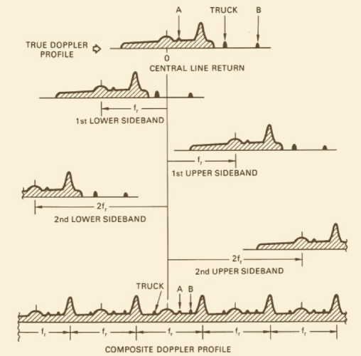
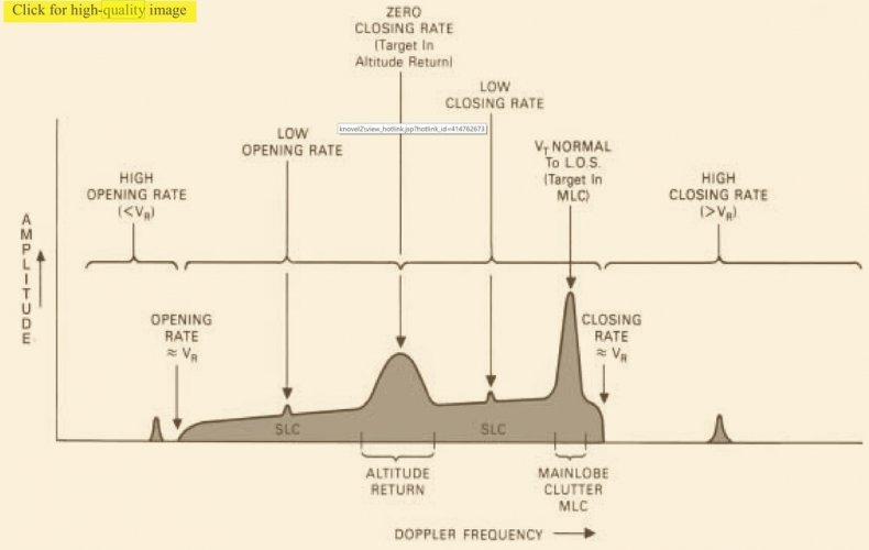
Because the PRF width is narrower than the actual spread of true velocities, the radar's internal spectrum folds over on itself. This creates a Composite Doppler Profile where the high-power Main-Lobe Clutter (MLC) peak repeats at exact intervals.

This causes MLC peaks to fixed and repeated in the folded spectrum "every 1100kmh"

In lookdown there are 3 scenarios:
When the target has no radial closure (0 closure), their doppler drops down to 0 and the target is burried within the MLC peak, this causes the radar to start tracking the ground instead, (which can be noticed by the rhombus and targetting circle being stationary/moving only in relation to the ground)
When the target has +1100kmh radial velocity the target is closing, which causes its doppler frequency to fold exactly into the next MLC peak, which again causes the radar to start tracking the ground OR the target IF and only IF their signiture is strong enough at very low ranges (under 10km like the manual cites) because bare metal reflects EM waves a lot better than dirt, so the relative target signature is stronger than the MLC
When the target has -1100kmh radial velocity the same occurs as with +1100, their true doppler frequency folds again onto the next negative MLC peak, causing the radar to start tracking the ground or target at low low ranges (under 10km)

However, in lookup situations everything changes.
Since the 1100kmh radial velocity limit only applies when MLC is present, when the radar antenna is pointed upwards, the MLC disappears, this means the target doesn't fall into any doppler frequency bright spots caused by MLC and only has to combat the SLC. This can also occur in shallow lookdown cases, or at high altitude lookdown cases as the MLC is going to be weaker than the target signature or the lesser your radarn is pointed downwards.

All this information was obtained from the MiG-29B on filtering algorithms for ОБЗОР and РНП 3.3 Измерение координат в режиме непрерывной пеленгации page 138.
 
Last edited:
1789466098200.png
in ОБЗОР (search) mig-29 radar scan frequencies just between 2 nearest MLC peaks

The N019 uses a 3-PRF schedule to cross-reference and unwrap true velocities. Because it can only resolve 3 adjacent zones, it has a strict physical speed limit spanning -2,200 km/h (receding/tail-chase) to +1,100 km/h (closing/head-on)
 
which causes its doppler frequency to fold exactly into the next MLC peak, which again causes the radar to start tracking the ground
Idk what passage you are referencing for it to transition from 4/4 to ground track, as I answered you on ED forums this is only for look down situation in modes D/AUTO in ZPS, which would be angles of 3/4-0/4.

And I don’t think MLC ever truly disappears. Only becomes small enough for high enough SNR to track in it.
 
Idk what passage you are referencing for it to transition from 4/4 to ground track, as I answered you on ED forums this is only for look down situation in modes D/AUTO in ZPS, which would be angles of 3/4-0/4.

And I don’t think MLC ever truly disappears. Only becomes small enough for high enough SNR to track in it.
This isn't the ED forums, I'm talking about the Persuit radial speed limit in general right now, not specifically the lookdown 4/4 track.
 
Regarding tracking in 4/4 aspect (notch/0 radial velocity):

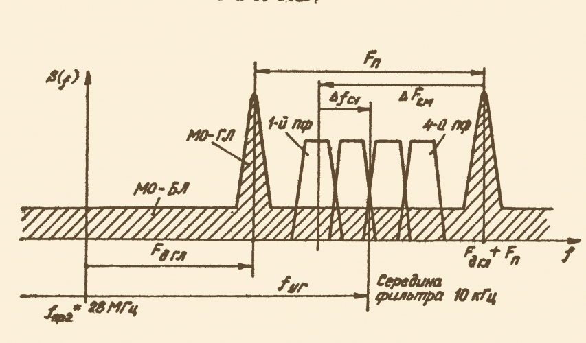
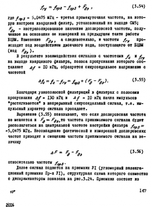
The RNP/STT Doppler processing is not simply a fixed "notch filter" that rejects everything below a certain radial velocity. The received target signal is first selected by range and passed through the Doppler-processing channel. The system then uses an extrapolated Doppler frequency (F_de), calculated from Doppler measurements from the previous tracking cycle, to control a local oscillator. After mixing, the resulting frequency is essentially determined by the difference between the actual target Doppler (F_d) and the predicted Doppler (F_de).

The signal is then passed through a narrow 10 kHz filter centred on the reference frequency. When the actual Doppler matches the predicted Doppler, F_d = F_de, the signal falls directly in the centre of this filter. Therefore, the filter effectively follows the predicted Doppler of the tracked target rather than remaining at one fixed velocity. If the target's Doppler changes, the signal moves away from the filter centre until the system updates its prediction during the next tracking cycle.

This is particularly important for look-down/notch situations. If the target performs a notch manoeuvre and its radial velocity decreases, its Doppler frequency also decreases. Since the tracking channel follows the predicted target Doppler, the filter will follow this decreasing Doppler as well. If the predicted target Doppler enters the same Doppler region occupied by MLC or SLC, the 10 kHz tracking filter can overlap the ground clutter. The issue is therefore not necessarily that the radar has a fixed "same-speed filter" that rejects the target; rather, the target's predicted Doppler can move into the clutter region, allowing the much stronger ground return to compete with or overwhelm the target return.

1789500459215.png
 
Or don’t forget how SLC altitude return line stops reception of targets with similar radial velocity or small closure in rear aspect, which any pulse Doppler radar is going to have issues with as the sidelobe is hitting ground directly below you. IMG_7286.jpeg
 
Last edited:

Similar threads

Back
Top Bottom