http://www.radioland.net.ua/contentid-452-page1.html
1 PURPOSE OF STATIONS
Aircraft radar TsD-30T is designed to work in a complex of means of interception and destruction (rockets RS-2-U) aerial targets.
The complex is located on a fighter jet.
The station provides:
· Automatic review of space in a particular sector of the front hemisphere and target acquisition;
· Semi-automatic target acquisition and tracking range and angular coordinates;
· Aim through the display and defeat the purposes of guided missiles;
· Determination together with the equipment identification nationality detected aircraft.
2 OPERATING PRINCIPLES
The station TsD-30T in a combat mission can be divided into 3 stages:
1 review of space and target acquisition;
2 output to the starting position for the attack;
3 attack targets and guidance guided missiles at the target.
In browse mode antenna produces irradiation space forward hemisphere in the sector of ± 30 degrees in azimuth and ± 12 degrees in elevation.
Elevation center sector review may be below the horizontal axis of the plane truss angle - 4 degrees, or - 6 degrees depending on the altitude of the aircraft.
Formation search pattern shown in Fig. I. Move the antenna beam in space is the result of adding the three easy steps:
1 in azimuth movement leftward and rightward at a uniform rate;
2 jumps elevation up or down at the end azimuth lines;
3 conical scan.
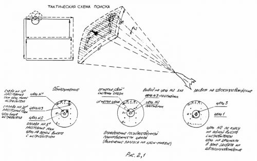
In the presence of targets in the Gaza review at ranges up to 20 km reflected RF signals received by the antenna are converted and amplified by the receiver, and then fed to the indicator type "B" (azimuth-range).
Fig. 2 shows the image on the screen display purposes in different cases. Targets on the display screen are reproduced in the form of horizontal luma marks with vertical labels. Target azimuth is measured from the center of the horizontal indicator, and distance along the vertical axis from the bottom of the raster. Position of the target elevation is displayed vertically labeled "top", "bottom", located near the marks purposes.
Before the start of the attack, the pilot should make sure that the observed plane belongs to the enemy armed forces. For this pilot identification system comprises an interrogator. If found the plane belongs to their armed forces over the goal mark a horizontal mark "their". The absence of such a mark indicates the detection of enemy aircraft. In this case, the pilot is maneuvering the rate and height so that the center mark aligns with the target zero azimuth and to the vertical mark was obtained from the top and bottom horizontal luminance level of the target.
When approaching the target at a distance of not more than 10 km and exit fighter on the target, so that it falls into the area of ± 5 degrees in azimuth on the middle line of view (ie, there are two vertical marks "top" and "bottom") , the pilot makes a takeover target.
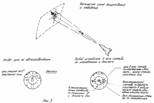
To capture target pilot presses the button "Capture" on the handle of the control plane. By pressing the button "Capture" antenna station stops review and becomes zero in azimuth and angle - 2 degrees to the longitudinal axis of the aircraft, as auto- searches targets range. If the level of the signal reflected from the target is sufficient to gate the capture machine, then there is a takeover target in range and light switches in the impact mode. In this case, the on-screen display appears artificial mark targets, shown in Fig. 3, which shows the image of the display screen work station when aiming regime. Besides artificial mark targets on the screen there are two symmetrical label range.
After the capture of the goal, the system automatically monitors the angular support of the angular coordinates of the position of the attacked target.
The angular position of the target in space corresponds to the position of the center of the artificial mark targets, and range interceptor-goal matches the distance from the center mark to the label range. Duplicate labels range is necessary in order to be able to determine the distance to one of them, since for sufficiently large deviation of the center of the artificial haulage goal from the center of the display screen, another tab will be shown on the screen.
Maneuver the aircraft pilot in aiming mode continuously support center artificial mark inside a small circle on the screen (the radius of the circle corresponds to one degree deviation). When the mark range is in the zone of fire, the pilot makes launch projectiles.
Flight control shells carried by radio beam. To get on the projectile reference voltage station with the start-up begins to produce special reference signals - "codes", which are shown in Fig. 8 station sends reference signals at the position of the antenna beam top-right-bottom-left of the beam with respect.
Generation system has a special code signals gyroscopic device that provides a mode of attack shells stabilize the spatial position of the code at the banks of the aircraft.
The station allows two modes of guidance shells:
1 Pointing Mode shells with automatic tracking.
2 Pointing Mode shells for a fixed beam.
Pointing Mode shells autofollow goals used in firing at a single target, regardless of visibility conditions with no interference. Shooting in this mode requires the pilot as much attention to the quality of piloting during the shooting, as the station automatically monitors the position of the target.
Guidance mode with a fixed beam is used in the presence of active and passive noise when fired on a group or a low-flying targets. Shooting in this mode requires the pilot attention and continuous precise aiming at the targeted goals as the station does not follow the target.
Equisignal line antenna in this mode is associated with the optical axis of the process.
Depending on the situation, the pilot selects and translates guided projectiles station from one mode to another tumbler "Support" - "fixed. Beam" - "noise" on the remote control station.
3 The station
The structure of the radar TsD-30T includes the following units:
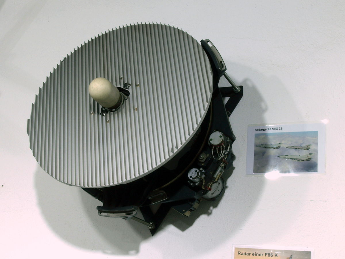
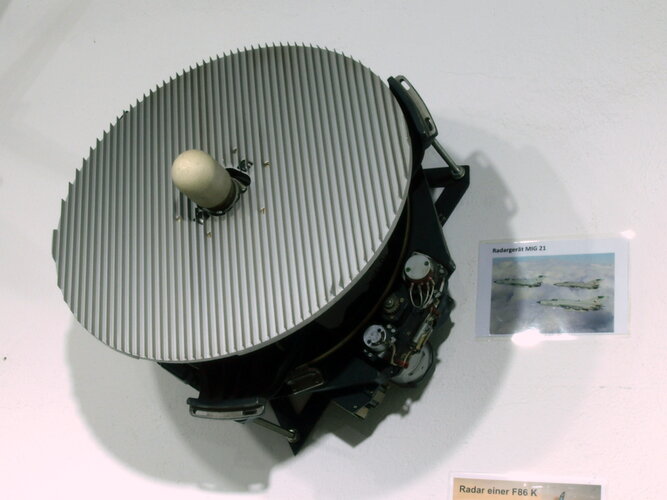
1 antenna unit.
2 receiver unit.
The receiving unit 3.
Indicator 4.
5 scanner.
6 unit of magnetic amplifiers.
7 The synchronization unit.
8 auto-.
9 power supply.
Block 10 Coordinate stabilization.
11 Antenna Control Unit.
The control unit 12.
13 Junction box.
14 protection unit asynchronous pulsed interference.
Correction unit 15 in height.
Work stations provide the following devices:
1 height sensor.
2 Converter 36V 400Hz PG-200.
When working in ground conditions using ground control monitoring.
4 DESCRIPTION OF STRUCTURAL SCHEME STATION
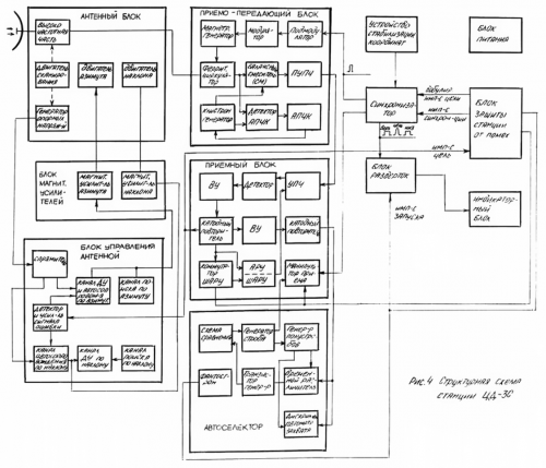
Block diagram of the station TsD-30T is shown in Fig. 4.
Antenna unit - used for emission and reception of high-frequency signals and beamforming. Here are the engine beam scanning, the reference voltage generator and motor control in azimuth and elevation. The RF signal received at the antenna to the magnetron oscillator transceiver unit.
Receiver-transmitter unit - next generation of powerful high-frequency pulses and converting high-frequency pulses reflected from the target, in the intermediate-frequency pulses, and also carries out pre-amplification of signals at an intermediate frequency. It consists of a modulator that controls the magnetron oscillator; mixer (CM); Pre-intermediate frequency amplifier (HURIST); and automatic frequency control circuit klystron oscillator (APCHK). The signal output from the target HURIST supplied to the receiving unit.
The receiving unit shall be:
· Gain reflected the goals and converted to an intermediate frequency signals and their detection and delivery of enhanced video signals to a display device, avtodalnomer and antenna control unit;
· Selektirovanie channel gain range;
· IF automatic gain control signal but the goal (AGC);
· IF automatic gain control on noise; (BALL)
The output video signals of the receiving unit in the following blocks:
· On the protection unit;
· Rangefinder;
· Antenna control unit;
The composition of the receiving unit includes:
· An intermediate frequency amplifier,
· Detector and video amplifier
· Cathode follower,
· Switch automatic gain control on noise (BALL).
· AGC and SHARU
· Manipulator reception performing unlocking IF only at the instant when the positive pulse BALL or positive pulse selector receiving positive or strobe pulses auto-.
The display unit (combined indicator review and auto-tracking); intended:
·-For visual detection marks purpose;
·-For targeting by defining the indicator:
angles in the vertical and horizontal planes, between the direction of the target and the longitudinal axis of the aircraft;
distance to the target,
"Zone start."
In the display unit is used electro-ray tube type "Tower 1".
Scanner - controls the display and provides:
· Production in browse mode voltage sweep needed to create on-screen indicator sweep type B;
· Production in auto-tracking mode voltage sweeps required to create on-screen indicator sweep type "swimming spot" with the third coordinate - range;
· Production of a voltage pulse, the duration and whose position on the scan range and the "floating spots" is defined on the "start zone".
· The production of pulses unlocking required for the normal functioning of the tube "Terem-1."
Antenna control unit provides:
· Expansion of the error signals in two mutually perpendicular planes of azimuth and inclination.
· Amplification and conversion of the error signals constituting axis azimuth and tilt driving currents.
· Strengthening and transformation of the signals in the servo systems remotely install the antenna in azimuth and tilt axes.
· Generation of signals found for azimuth and tilt axes.
Antenna control unit consists of the following main elements:
· Chain allocation error signal
· Channel formation control currents to the tilt axis in the search mode,
· Channel formation control currents on the azimuth axis in the search mode,
· Channel formation control currents on the azimuth axis in auto-tracking mode and remote system (PS).
· Channel formation control currents to the tilt axis in auto-tracking mode and control.
Antenna Control Unit works in three modes:
1 review mode space
2 automatic target tracking in the corners,
3 mode remote antenna installation is to install the antenna in a certain position when you press the sensor button "Dist. Installation" (control).
In the auto-tracking mode to the input unit receives:
· Amplitude-modulated by video modulation depth and phase of which depends on the position of the beam with respect to the goal.
· Reference sinusoidal voltage with the GON.
· Sinusoidal voltage VT.
The control signal output from the antenna control goes to block magnetic amplifiers.
Unit of magnetic amplifiers designed for power amplification control signal antenna. The amplified signals from the unit of magnetic amplifiers are fed to the engine bearing and engine tilt antenna.
Auto- is:
· To automatically search for the purpose of range with automatic accompaniment one captured auto- purpose.
· To indicate the time the target lock and move the radar to auto-tracking mode.
· To unlock the receiver radar station at the time of exposure to the reflected signal from the tracked target, ie gating the receiver.
Auto- consists of:
· Temporary discriminator,
· Phantastron,
· Generator slow saws
· Comparison circuit
· Strobe generator
· Schematic capture.
Auto- work is no different from the work of typical circuits auto-.
Video pulses goals for auto- come from the receiving unit.
Produces an output pulse gating the receiving unit.
Junction box serves to connect all of the blocks between a station and its numerous switches which are necessary during work station.
The power supply is stabilized power supply on board the aircraft, powered by the inverter software-1500 / 115V 400Hz /.
After a brief introduction to the basic building blocks of the station, which is no different from those in other radar units, it is advisable to become familiar with the TsD-30.
5 PROTECTION DEVICE STATIONS Surge
This device provides:
1 synchronization of the entire station.
2 The efficiency of the station in the presence:
Mismatched impulse noise,
synchronous impulse noise reflected from distant objects and local arriving at the second and third period of the station.
In device protection against harmful interference station includes the following units:
· Power Protection from non-synchronous impulse noise (block 25). Providing protection from interference and synchronization of the station.
· Synchronizer (block 36), gives an impulse to start the transmitter and receiver.
· Receiver (blok 38) undergoing protection from synchronous impulse noise from distant targets.
· Junction box (block 42), providing a switching circuit of the relay.
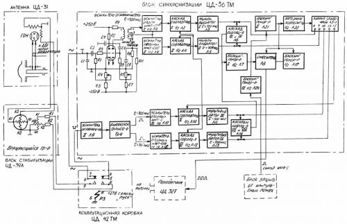
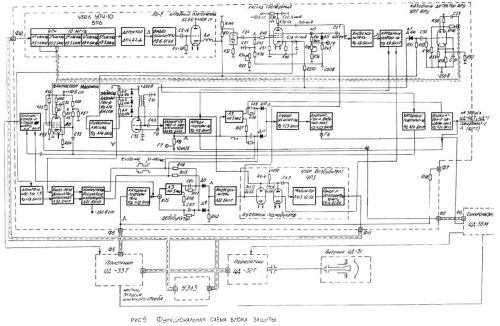
Functional diagram of the device shown in Fig. 5.
Synchronization of the station to ensure strict sequence of trigger pulses, frequency of which is determined by an ultrasonic delay line (UZLZ). The delay is T UZLZ microseconds.
With the self-excited blocking oscillator 25L14, (having a natural frequency of about 1500 Hz repetition), a negative pulse is fed to 10-20 microseconds grid modulator 25L4-3 controlling agent 25L4-4. Momentum of the pathogen 10 MHz excites UZLZ quartz, built on 10 MHz. Quartz converts electrical oscillations into mechanical that linger in the delay line.
At the exit UZLZ is also tuned to the frequency of 10 MHz quartz second, converting mechanical vibrations into electrical. Weak electrical oscillations in the second quartz UZLZ enter the HRO-10, where the amplified lamps 25L5-1 - 25L5-5 and detected D5-1.
The detected video pulse amplified video amplifier 25 L5-6 and through a cathode follower 25l5-7 supplied to the lamp of the self-indulges blocking oscillator 25L14 synchronizing last. Thus, defining the blocking oscillator 25L14 will samosinhronizirovatsya delay determined UZLZ.
This way of working of the master blocking oscillator leads to a high stability of the repetition period (T) of the clock signal.
Protection Station of nonsynchronous impulse noise protection is provided by a special circuit, which consists of:
· The coincidence circuit 25L8, providing transmission of video pulses only in case of a match delayed by the repetition period and the delayed single-cycle target.
· The delay circuit providing a delay of a video on the pulse repetition period.
· Integration scheme, providing an increase in the amplitude of the video signal.
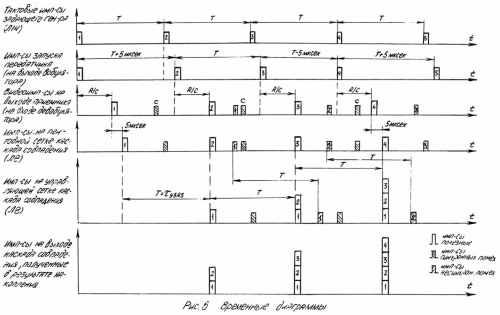
The principle of operation of the circuit protection is carried out by the coincidence of the detainee to the repetition period and the delayed pulse goals and explains the timing diagram shown in Fig. 6.
Lowpass goal output from the receiver through a cathode follower half 25L13 is input devobulyatora, the output of which is fed to the grid of the amplifier 25L22. Reinforced video pulses are fed to the grid pentode stage matches 25L8 and the amplifier unit 4PZ 25L4-2.
Further objectives pulse, as previously described synchronization pulse passes modulator exciter UZL and HRO-10.
The detected and amplified in the video amplifier 25L5-6 momentum goals through a cathode follower 25 L5-7 and correcting delay line to 0.1 microsecond (25-LZ-1) are fed to the control grid of the cascade coincidence 25L8. Along with the detainees UZL8 momentum goals for the next stage match video pulse is applied to the pentode goal keeper.
As a result of coincidence in time videopulses goals in two grids at the output of the coincidence circuit a pulse target, which is amplified and over half 25L9 cathode followers 02.01 25 01.02 25L15 L9 and fed to the input of the relay. Amplified pulse coincide with 25L9 is also fed to the amplifier unit 4NC L4-1 where combining with the pulse video amplifier L4-2 not detained tract affect the modulator and exciter.
As a result of adding the output of the coincidence circuit is an increase in signal amplitude from pulse to pulse - the effect of integration.
Asynchronous interference pulses, the repetition period is different from the frequency of repetition of the station, but in the same time on the grids stage matches and will not pass through the circuit stage matches.
Probability of coincidence of noise pulses is reduced by the chaotic sequence and the presence of the cut-off on the control grid of the tube stage matches 25L8.
Due to the cut-off on the control grid of the tube coincidence signal integration begins with a threshold, and the output of the coincidence circuit there is a significant increase in the signal / noise ratio.
Thanks to the feedback circuit protection / integration /, a compensation of loss in sensitivity due to the coincidence stage cutoff.
Protection of synchronous radar path impulse noise coming from their own probe pulses and falling on the second and third period of the station is provided by the wobble (modulation time) parcels of probe pulses.
To ensure correct operation of the relay in the first period of the station used devobulyatsiya wobbling reflected pulses from the target.
The trailing edge of the master oscillator bloking- 25L14 run blocking oscillator 2.1 25L15, the momentum from which directly or delayed by 5 microsecond delay line vobulyatora arrives at the launch of the next blocking oscillator 25L23. Pulse with a cathode load blocking oscillator 25L23 issued for the launch of the synchronizer, which starts with the transmitter.
Lowpass target output from the receiver CD-33 CD-protection unit 25T through a cathode follower half P3 immediately or delayed by a five microsecond delay line de vobulyatora, 25L22 applied to an amplifier, which is fed to the stage through the amplifier and matching 25L4-2 node 4P3 modulator.
Switching vobulyatora and devobulyatora by a special switching pulse from the circuit switch. And wherein the wobble devobulyatsiya phased so that when the trigger pulse transmitter for the first cycle does not zaderzhvaetsya, the purpose of the first clock pulse passes in a cascade match the delay and vice versa, at the 2nd and 3rd cycle start pulse transmitter is delayed, and after devobulyator pulse passes un-delayed goal.
Switching delay of a video goal and trigger pulse performs a flip-flop 25L20, which run on a grid made with period T pulses of the master blocking oscillator, and on the other grid pulses blocking oscillator frequency is divided into "1 3" (I / 2 25L13) with period 3T.
With this switch trigger pulse and video pulses goal obtain simultaneous arrival on stage coincidence pulse purpose video amplifier with 25P22 and momentum goals came through UZLZ. This match will exist on the arrival of the reflected pulses goals in the first period of the station. With the arrival of the reflected pulses goals in the second and third periods of the station from the probe pulses of the first period at the same time entering the cascade coincidence pulses 25L8 detainees UZPZ undelayed and will not exist. These pulses are reflected through a cascade of coincidences will not work, and thus do not fall on the display device.
To exclude the operation of the receiver BALL CSD-33 on its own pulse is reflected from distant targets with the launch of its produced wobbling pulse is removed from the blocking oscillator 25L12. Blocking oscillator starts from phantastron 25L11. Pulse duration phantastron modulated voltage frequency 380-900 Hz.
6 DEVICE Formation and stabilization of the alarm codes for projectiles
To ensure management shell for automatic target tracking device formation and stabilization of code signals creates the reference signals in the form of pairs of high-frequency pulses generated by the transmitter at the time of the passage of the scanning beam antenna position, top-right, bottom-left relative to the axis of the aircraft.
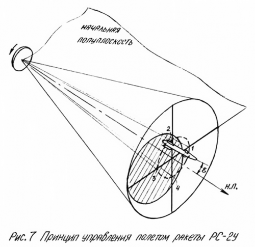
Before turning to the analysis of the functional circuit device formation and stabilization of code signals is advisable to understand the principle of rocket flight control the PC-2-U, which is armed interceptor. The principle of rocket flight control RS-2-U is illustrated in Fig. 7 and is the following.
Station TsD-30T, located on board the aircraft, creates a space equisignal line on which the rocket is sent to the target. In the event of a rocket from the on-board radio equipment line equisignal missile control the RS-2-U generates control currents. The value of the control currents proportional to the modulation depth of the received radio signal, and determines the amount of deviation of rudder steering apparatus of control and stabilization.
Distribution of control currents to the control channels and the polarity of the current in each channel is dependent on the direction in which the missile to deviate from the equisignal line. Data providing information on the direction of the rocket equisignal care lines are contained in the structure of the radio and on-board radio equipment disclosed by decrypting it.
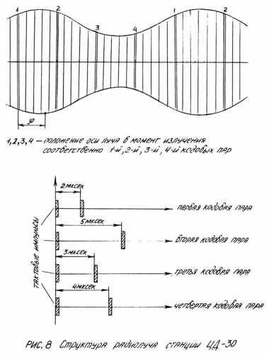
The radio signal station TsD-30T consists of a sequence of radio pulses emitted. Among the basic series of single pulses Scanning System station for one turn emit four paired pulse, the so-called code pairs - one through each quarter turn of the antenna. Fig. 7 digits 1,2,3,4 observed position of the beam at the time of radiation, respectively, first, second, third and fourth pairs of code. Code pairs differ from one another by time interval between pulses in a pair. Moments radiation code pairs correspond to a strictly defined position in space beam station. On their base-board radio equipment generates reference voltages required to generate control signals for azimuth and elevation.
The structure of the radio beam station CD-30T is shown in Fig. 8.
The left half-plane for the flight, which is the axis of the scanning beam of radiation at the time of the 1st code pair taken as the initial value. From her measured phase angle φ envelope modulation radio signal arriving at the antenna of the rocket. The value of φ is measured clockwise at the sight of a flight - in the direction of rotation of the beam. Fig. 8 is a graph of the received radio signal rocket. As can be seen from the graph, the 1st pair of code - according to the situation depicted in Figure missiles - is shifted by an angle φ from the highest point of the modulation envelope of the received radio signal.
In forming apparatus and stabilizing code signal consists of the following components involved in the work:
· Protection unit impulse noise, emits a pulse start;
· Synchronizer issuing coded synchronization pulses;
· Transmitter issuing coded frequency pulses;
· The system emitting high-frequency pulses of the transmitter and gives reference voltage for generating code signals;
· Stabilizing unit, which provides stabilization of the reference voltages of the antenna;
· Junction box, which provides switching at work blocks.
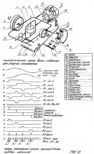
Fig. 9 is a functional block diagram of the device formation and stabilization of the code signals.
Binding code of signals to the corresponding spatial position of the scanning beam antenna is provided by the reference voltage output reference voltage generator. GON is set to the antenna and rigidly connected through a gear transmission 1: 1 with an antenna feed. Reference voltage generator outputs two sinusoidal voltages which are shifted between themselves by 90 °. These voltages are fed to the rotor of the rotary transformer (VT) unit stabilize the reference voltage.
Rotop BT fixed to the axis of the outer frame of the gyroscope, the stator housing stabilization unit rigidly associated with the axes of the aircraft. Fig. 9 shows the kinematic scheme for stabilizing the reference voltage, and stress distribution channel formation code pulses are shown in Fig. 10.
At the time of launch rockets voltage +27 V is supplied to the electromagnet, which removes the lever, releasing the cone, pushers and thereby causing, razarretirovanie outer and inner frame of the gyroscope. Thus, rigidly attached to the aircraft axes stator BT will rotate relative razarretirovannogo rotor aircraft roll, keeping the aircraft in coordinates relative to the moment of start-up phase of the reference sinusoidal voltage supplied from the GON antenna.
Since the stator BT stabilized phase sinusoidal reference voltage received on a sync block forming an electronic circuit for startup code pulse transmitter.
In the electronic circuit of the synchronization unit sinusoidal voltage is applied to the control grid amplifiers limiters 36L1 and 36L9. At the anode of the second amplifier stages included differentiating 36Tr2 transformers and 36 TP4.
With their secondaries removed reference pulses of positive polarity pulse width of about 600 microseconds, corresponding to the phases of 0, 90, 180, and 270 degrees of the reference voltage supplied to the GON and the control grid amplifier reference voltage 36L2, 36L4,36L10, 36L12 (left half).
Reinforced negative polarity reference voltages supplied to the cathode stages matches 36P2, 36P4, 36P10, 36SH2 (right half), opening them. To the control grid of lamps cascades coincidence pulses are applied repetition rate. The first one passed through the stages of coincidence pulse launches multivibrators 36LZ, 36P5, 36L11, 36L13. Pulses of positive polarity and a duration of 700 msec, with anodes multivibrators fed to the control grid of the second stage matches 36L6, 36L14 (both grids), for the same lamp with delay line 36LZ-1 pulses are detained with respect to the pulse repetition frequency for 2,3,4 and 5mksek. When the coincidence of pulses from the delay line pulses multivibrators, will start up the blocking oscillator 36L7 (left half). On the third winding of the pulse transformer pulses of positive polarity are fed to the control grid of the mixer, the other control grid comes not delayed pulses repetition frequency.
The output pulses are fed to the mixer launch transmitter. Delay pulse corresponds to the following phases of the scan feed:
· 2 microseconds for Phase 0 °
· 5 microseconds for 90 ° phase
· 3 microseconds to 180 ° phase
· 4 microseconds to 270 ° phase
Report of the angle being clockwise when viewed in the direction of flight.

")