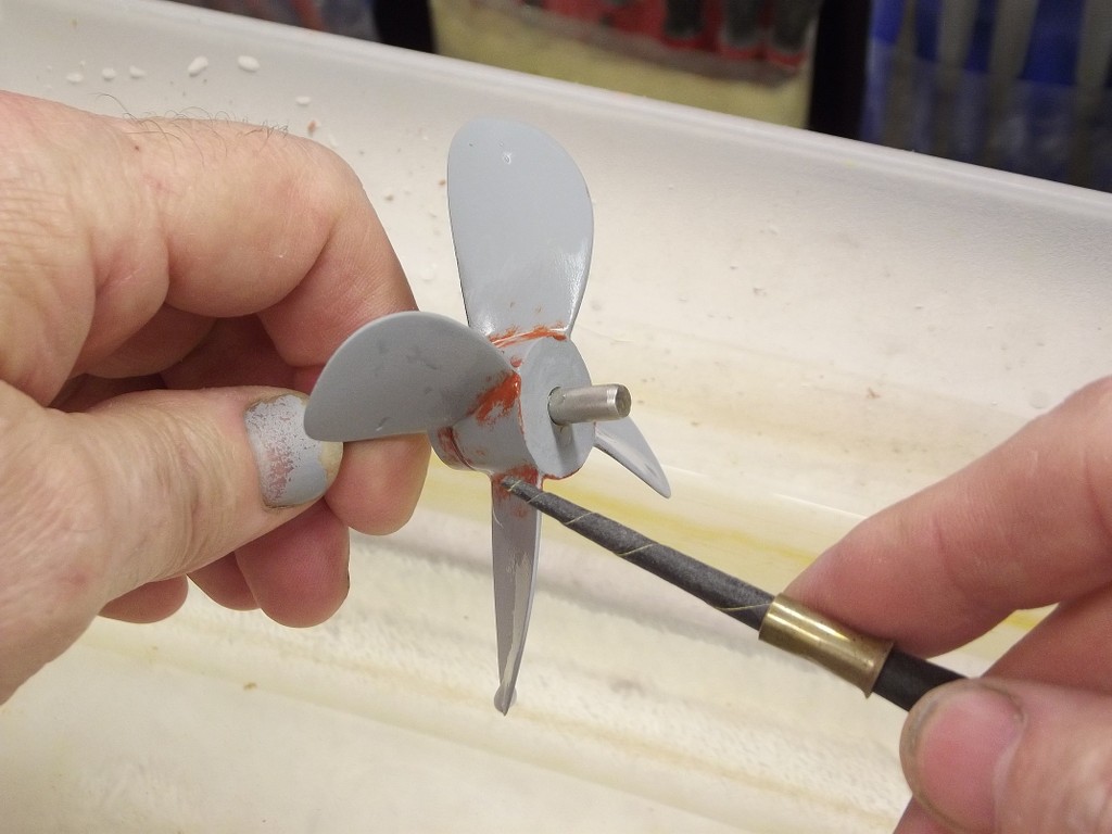
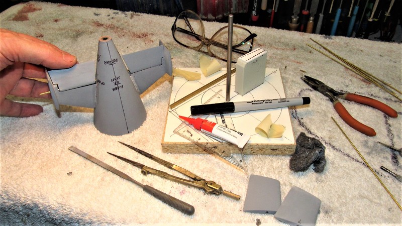
Jimeba: I found more photos to describe my riffler files as well as their use.
Also, you mentioned the use of abrasive paper wrapped around a dowel. A variation on that theme is a 'twist' of tightly rolled sandpaper secured with a brass collar -- you might find this adaptation of the paper-on-a-stick tool a useful addition to your tool-box. Depending on how you twist the paper you achieve either a constant diameter cylinder or a tapered form. A most useful abrasive tool.
Back to work on Scott Terrey's beautiful little ALBACORE kit.
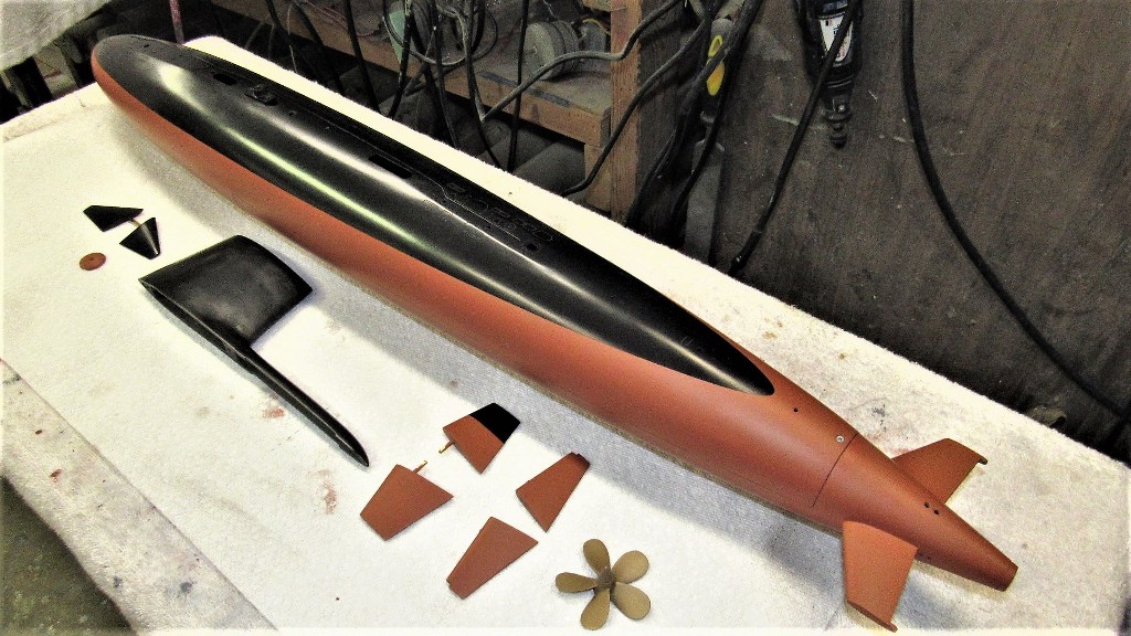
Here's a recap on work done in the last week. Almost ready for paint, only remaining task is to place external safety tracks atop the deck and fabricate railing for the sides of the sail. I'll attend to the safety tracks after I post this and will get onto the hand-railing tomorrow.
I had already gotten this model to the stage of operating it in the water, but still in primer gray. Here's a video of the initial in-water test of this little speed demon:
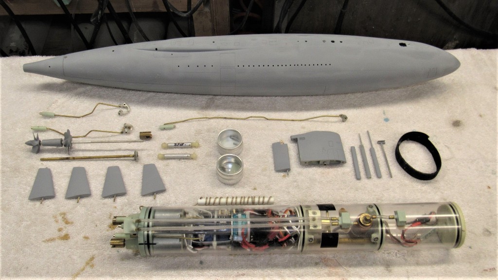
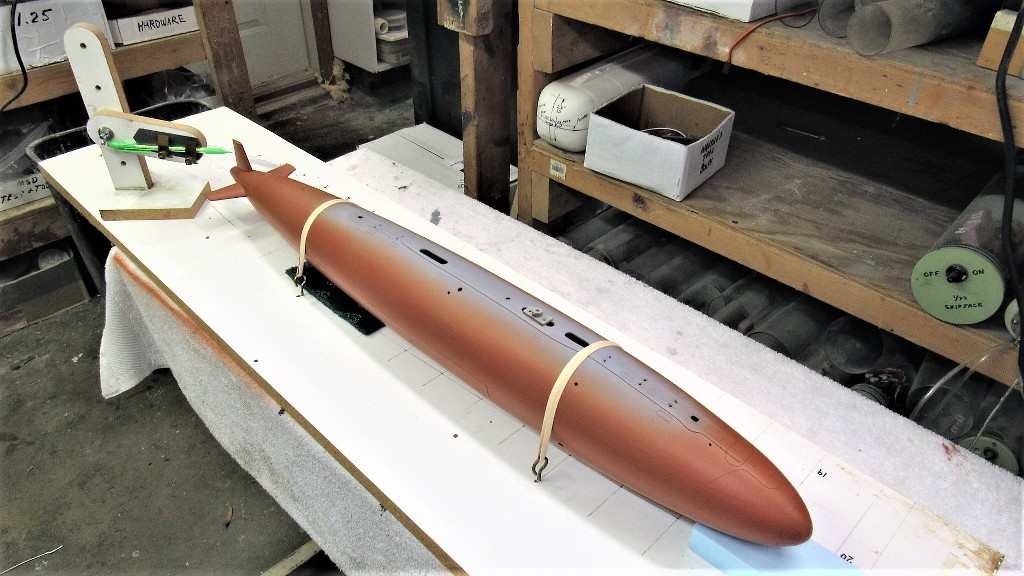
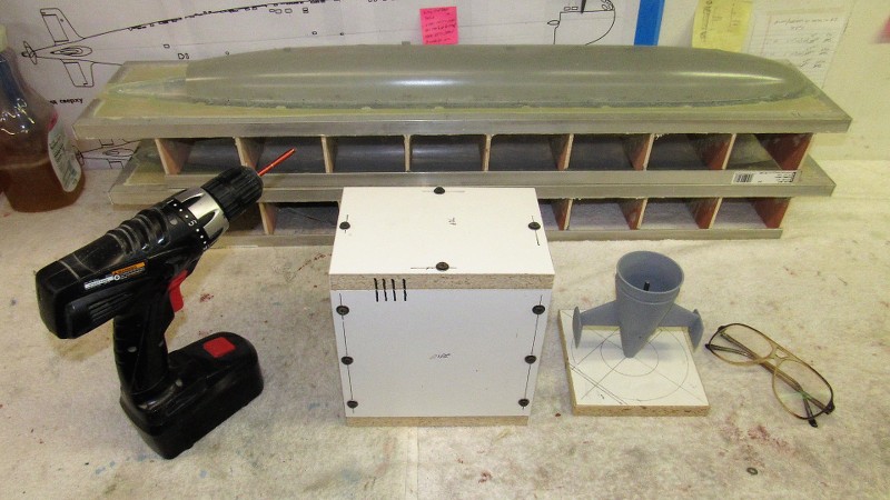
Returning home after that preliminary run I took it all down to parade-rest and placed everything in storage so I could go back to production work. Here's a look at all the devices, SD, and nick-knacks that go into making this model submarine work and look like a phase-4 ALBACORE. It all works... even the dorsal rudder works, it is slaved to its own angle-keeper -- oriented to detect and send corrective signals to the dorsal rudder servo to effect correction of motion about the roll axis. Pretty slick!
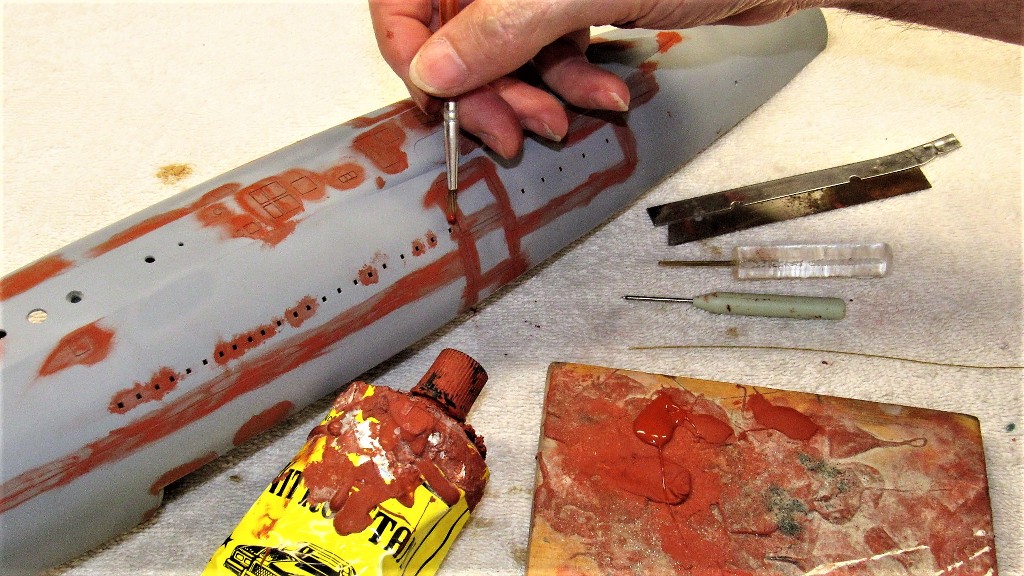
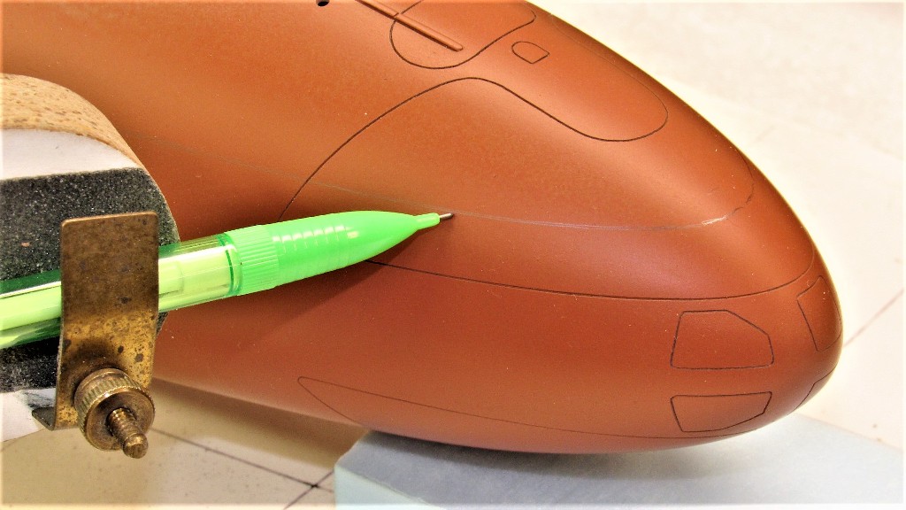
So, after I pulled the 1/96 ALBACORE hull down off the wall I dusted it off and started in on refining the existing engraving as well as adding more engraved lines I was able to identify from my research pile. Fortunately Scott's gel-coat was most receptive to the engraving process.
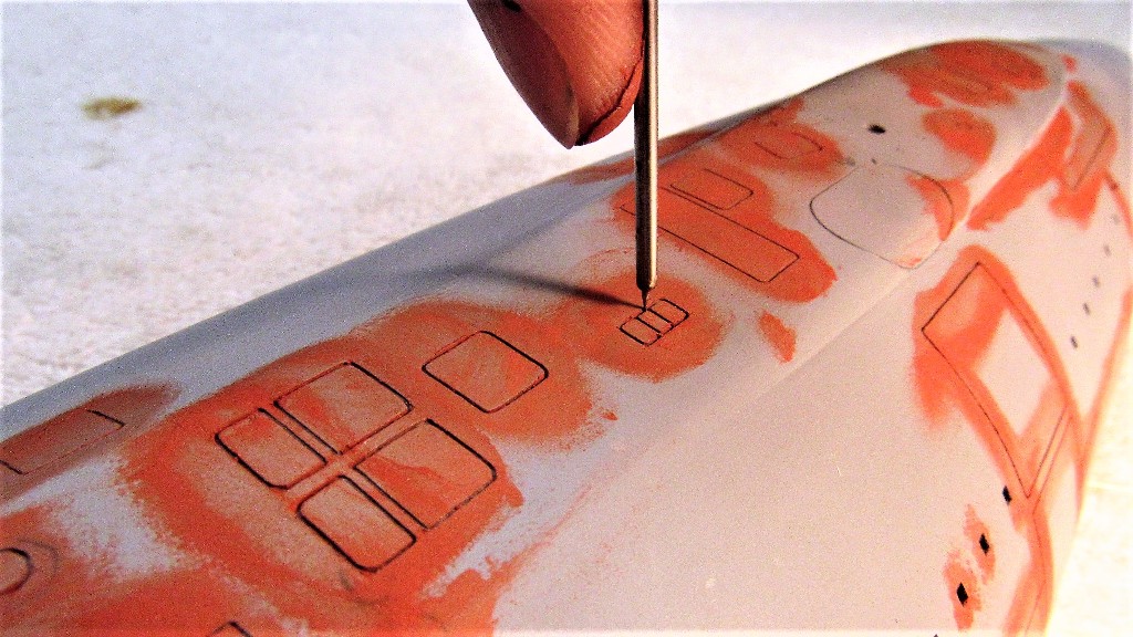
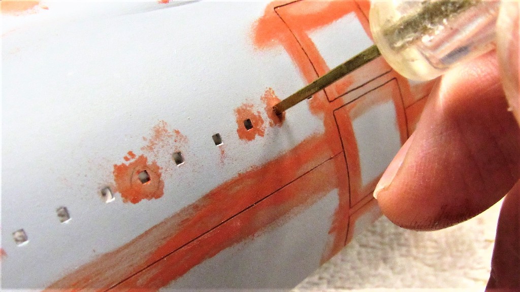
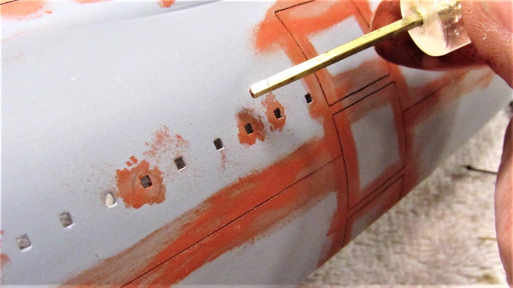
The square limber holes had their outlines tightened up with this tool that forces freshly applied putty to produce perfect, uniform of size, limber holes. The putty was applied with finger-tip or stiff brush, allowed to semi-harden, then the tool was pushed in to give final shape to the hole.
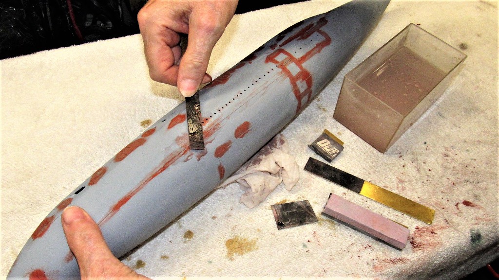
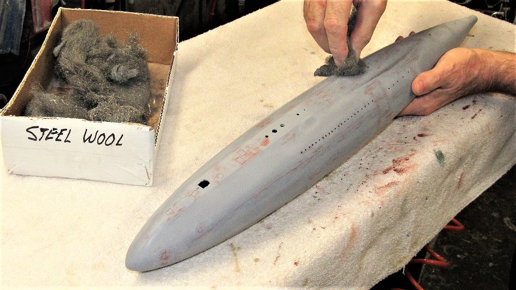
After the scribing and putty work --to fill the inevitable over-strikes during the scribing operations -- The dried putty was sanded flush with the surface of the hull by careful wet sanding with sanding blocks formed from #400 and #240 grit sandpaper glued to strips of .030" brass sheet. Once the hull had dried out I chased out the sanding dust with the scribing tool then scrubbed the surface of the engraved work with a hunk of #000 steel wool.
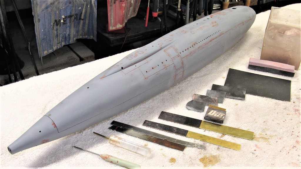
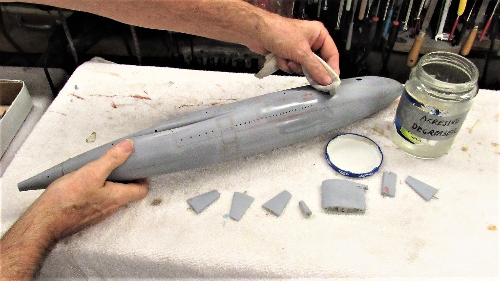
To remove any oil imparted by the steel wool I scrubbed the model with a cloth saturated with a semi-aggressive degreasing agent. This air dried quickly and I proceeded with another coat of primer over all worked areas of the hull and appendages. I'm now ready to glue down narrow strips of polystyrene sheet (or maybe round-stock?) to represent the safety-tracks used by crewmen who would tether themselves to it in order to prevent them being washed over the side in heavy weather (I can assure you, you don't want to be topside, on deck, in foul weather if your boat is a round-hull!).
Time had come to represent the sections of safety-track that run atop the hull, near deck level. In actuality these are T-section tracks, The bottom of the 'T' welded to the deck and the top of the 'T' becoming the race that accepts horse-shoe shaped runners that attach by lanyard to a sailor's safety harness. The idea is that once you shackle into the track you are free to run up and down the length of deck. Bull-shit! You almost always became a dog-snapped-to-a-halt-by-his-leash as the runner snagged the track. I wonder if they ever came up with something better?
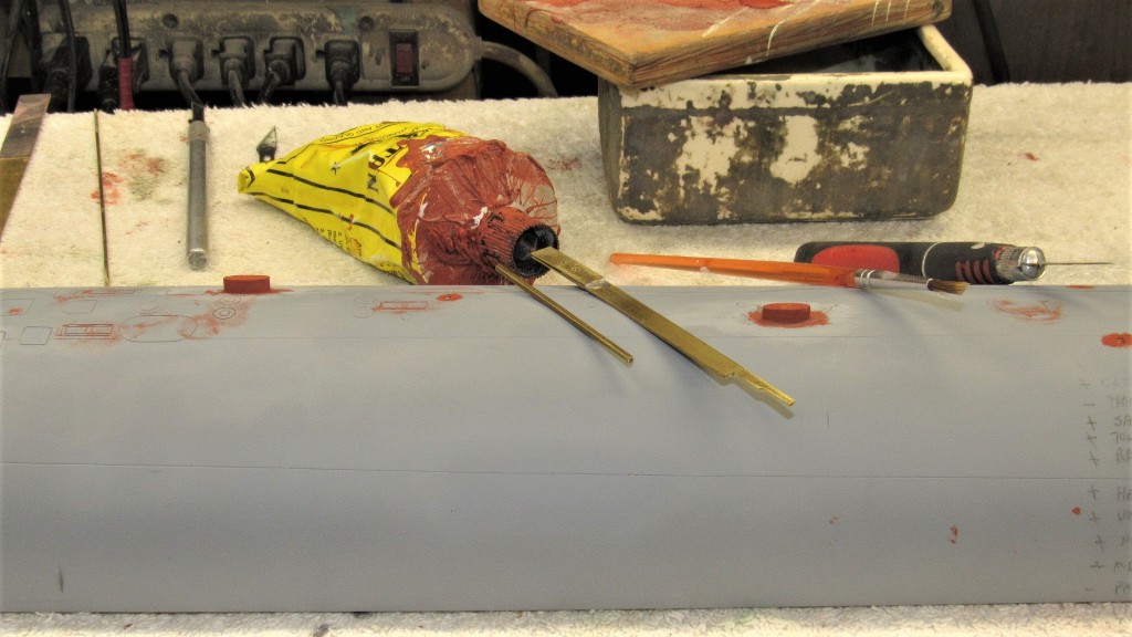
On the model I represented each section of track -- broken at points to clear line-locker hatches and such -- by a length of round styrene rod. As the real track was about three-inches in width, that comes out to a model width of about .031" at 1/96 scale. I dug a shallow trench where each of the five lengths of safety track would go and CA'ed each safety track in place. The work went surprisingly fast, an evenings work.
The only authoritative drawing I had representing safety-track placement was a plan I prepared for Skip Asay's 1/60 ALBACORE kit some twenty years ago. As that document was in 1/60th scale I was compelled to use my proportional dividers to mechanically transpose from that scale to the one I'm currently working, 1/96. The model so marked I dug out the trenches that would receive each length of round styrene.
Each length of rod was tack-glued in place with small drops of CA placed in the trench. Each trench stared as a deep knife slit in the deck done with the aid of a steel straight-edge. The depth of the cut increased with the aid of a razor-saw. I then used a modified rat-tail file, ground to shape to become a push-chisel, to give shape to the semi-circular trench.
I then applied a continuous bead of CA with the aid of an 'application knife' -- this tool worked to place the adhesive at the base of the rod from which it would wick down into the trench, insuring a strong bond with the minimum amount of glue requiring later clean up with file and sandpaper.
The CA was quickly zapped to a hard state with a liberal dosing of accelerator.
The 'flat' of the safety-track was achieved by simply sanding the rod flat at its top.
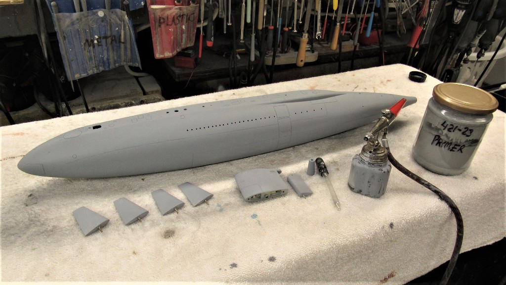
Some touch-up putty work and the model was sanded, touch-up primed, sanded again, and readied for painting by a good scrubbing with de-greaser.
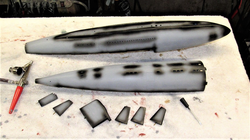
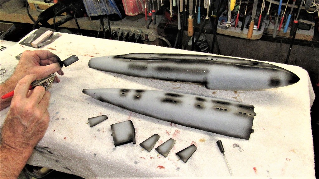
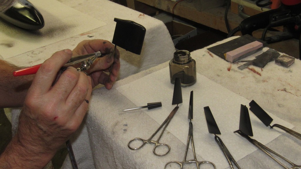
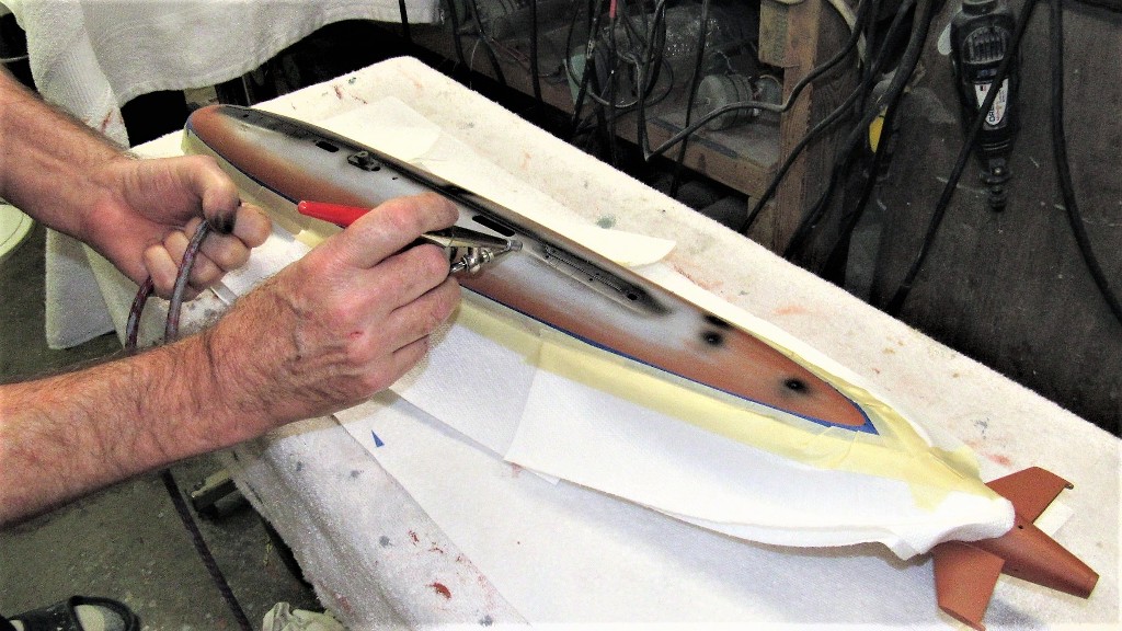
A dark, dark gray paint was mixed and spot applied to all edges, holes, and hard-to-get-at areas of the model.
I then blasted the entire model with the dark, dark gray.
I prepare a models surface for painting by a careful wet-sanding with #600 grit sandpaper. After drying the model parts, all surfaces are wiped with a tack-rag to remove any dust. And, finally, a de-greaser is wiped over the parts and they are left to dry. Only then does the first coat of paint go down.
(Hope Ellie does not read this post, as it would solve the, 'where do your T-shirts go?' mystery)
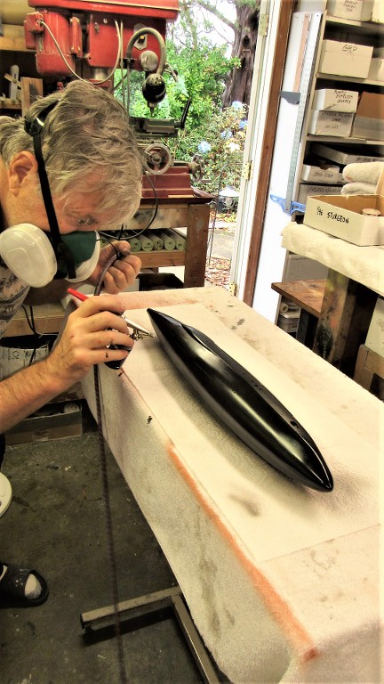
Time had come to paint the 1/96 ALBACORE black.
The preferred paint chemistry for my r/c submarine models is the two-part, polyurethane ChromaColor brand produced by DuPont -- no longer available... thank you, California!!! This is a great coating system: tough, UV tolerant, dries quickly, and the pigments are extremely opaque. I love the stuff!
But this stuff will tear up your lungs if a charcoal or forced air mask is not used. A word to the wise.
Once you mix the paint with its catalyst you have to use it within a days time or the paint will cure in the bottle. So, for economies sake (I can no longer buy this stuff... than you California!!!!) I plan my work so that more than one model will receive the color mixed. Such is the case here: I also laid down the black on a 1/96 SKIPJACK model I'm getting ready for the 2021 model boating season.
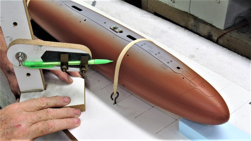
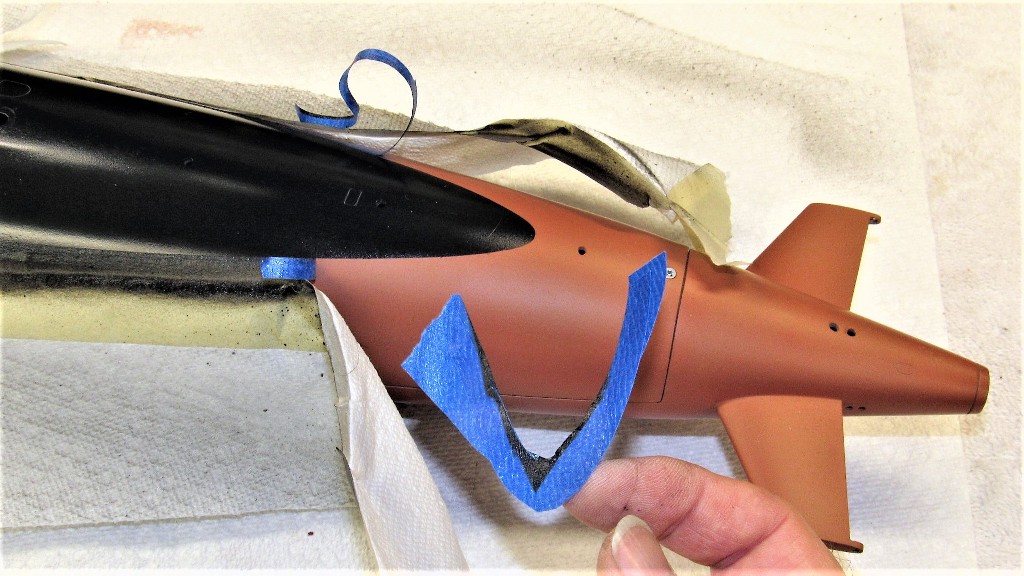
As this model had the red-black demarcation line at the boats designed waterline in surface trim, I had to first mount the model on a flat board, pitched up so that the waterline could be marked off with pencil with the aid of a 'waterline marking tool' (a pencil loaded Machinist's surface gauge, if you will).
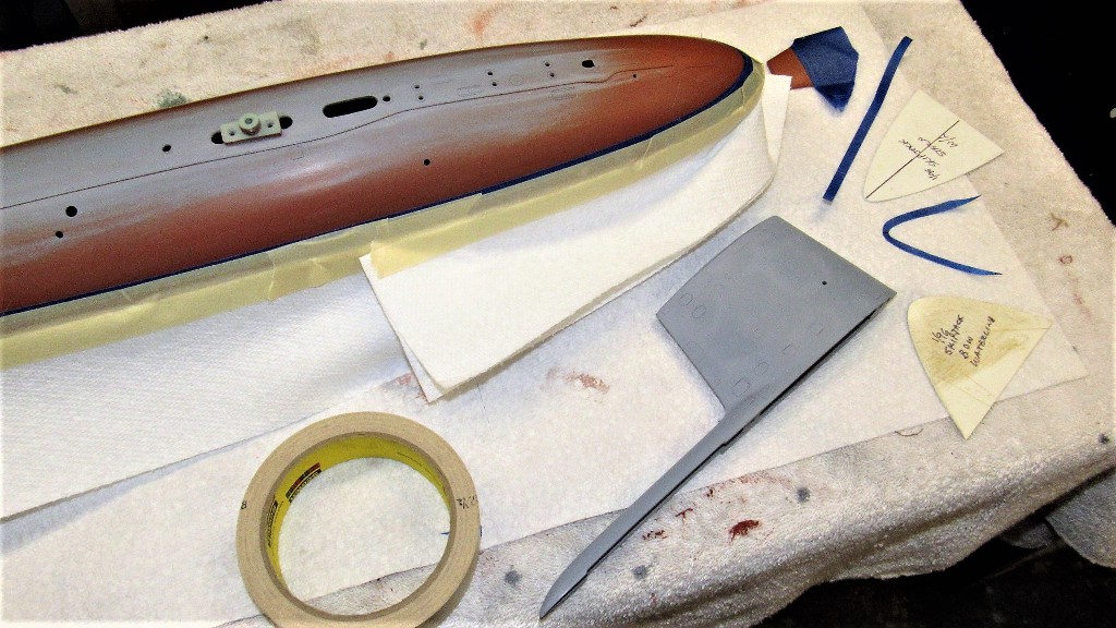
As this 1/96 SKIPJACK was far from my first, I broke out the old masking templates and used them to cut out masks for the pronounced curves at the bow and near the stern. These masks, and long straight strips were laid down on the model using the penciled cheat-lines as a guide. Paper towels were added to keep paint overspray from getting on the anti-foul red portions of the model.
Thank you, Mark. If you or anyone else needs amplification on a step or process, just ask. I have thousands of supporting pictures and a gift for gab that should answer just about any Craft question you come up with.
As always, marvelous and inspiring, fantastic step by step tut's that are transferable for any model making. A joy to see Sir. Thank you, lockdown would be much harder without this fix.
Still working on this 1/96 SKIPJACK. Today's effort was masking off the hull and sail planes and painting in the dark gray representing the non-skid surfaces. The painting itself takes seconds. The masking takes for freaking ever!
I'll have this thing ready for the 2021 Fleet-Run... American Revolution permitting of course. Hope this national enema is short lived!
Off the plans I made templates to guide me as I cut out masks to form the boarders between the lighter shade of gray representing the anti-skid areas and the rest of the hull.
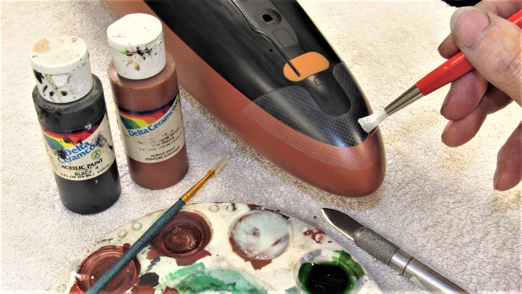
For small area coverage like this I'll use the cheap and much more easier to prepare and apply water soluble acrylic paints. You get those from Walmart or other such box stores -- these paints are in the 'craft' section next to the sparkle-powder and other such fluff.
To prevent fish-eye or runs I make several coats, drying each with the aid of a heat-gun before proceeding with the next coat. Next operation will be to lay down 'international orange' onto the two escape buoys, after which the entire model will be given a heavy clear-coat to protect the paint and form a barrier before I move into the 'weathering' phase of the paint job. That clear coat will permit me to 'erase' any goofs without damaging the underlying paint work.
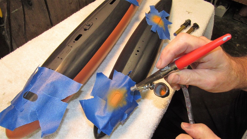
Two more things I painted onto the 1/96 SKIPJACK with the water soluble paint: The two marker buoys and a suggestion of the underlying geodetic support structure under the bow upper sonar window.
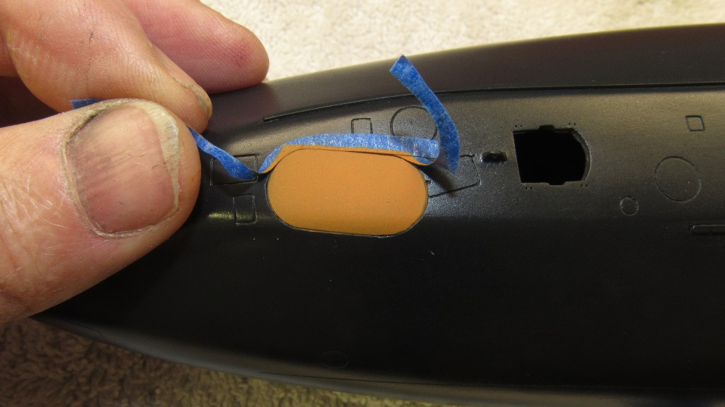
From red and yellow I mixed up an 'international orange' color for the buoys. For the SKIPJACK's geodetic pattern I simply shot some acrylic lacquer primer gray. While I was at it I also painted the two buoys atop the 1/96 ALBACORE deck.
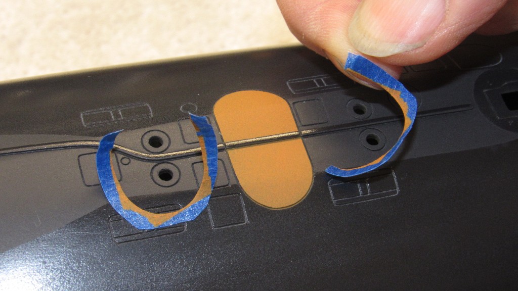
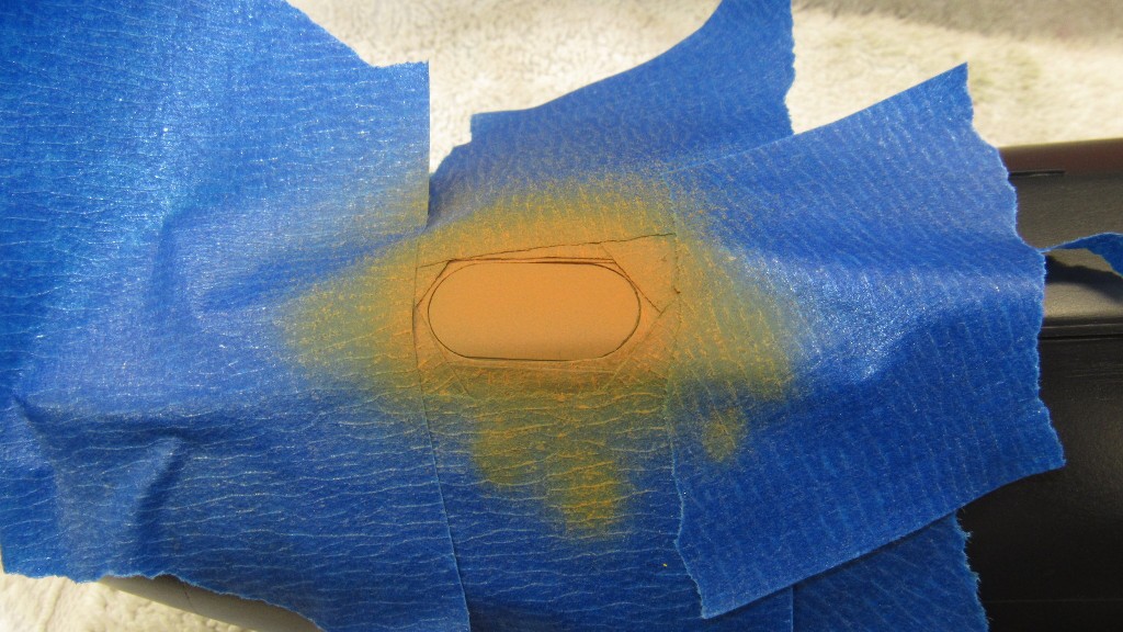
The hard part was masking around the ALBACORE and SKIPJACK buoy tops, this done with medium tack masking tape cut out with the aid of a sharp knife, punch cutters, and swivel-knife loaded compass. Additional over-spray masking was laid down and the paints squirted on with the ever reliable Paasche H-model spray-brush.
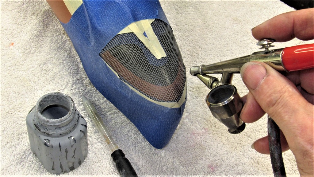
The mask used to represent the geodetic pattern was a piece of plastic window screen. It was secured in place after masking off the outboard outline of the sonar window, and primer gray lightly sprayed through the mask.
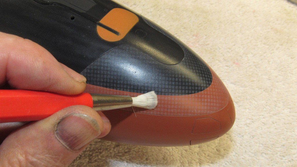
All masking removed I used an adjustable fiberglass eraser brush to scrub away some of the gray to render only a suggestion of the slightly dimpled surface of the sonar window. Such GRP sonar window sagging over time was much more evident on Soviet submarine of the time. Today, almost all bow sonar windows are steel.
There were some areas on the sonar window that need a little paint touch-up -- that done with the water soluble acrylic paints applied with a 0000 brush.
Now to protect all that work with a heavy coat of clear. After which I can move on to weathering and application of dry transfer hull and draft numbers.
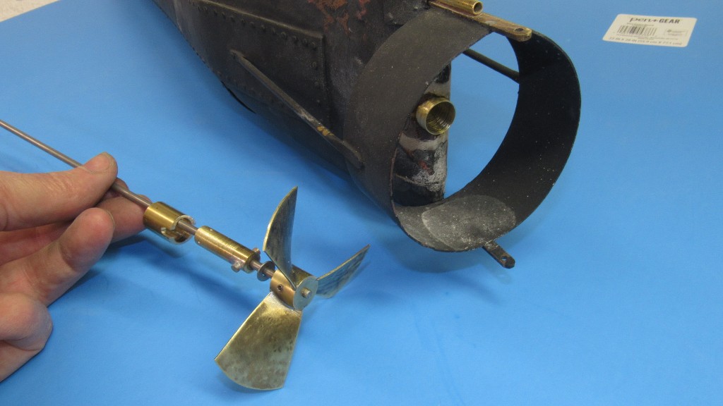
I've been helping a guy by restoring some model submarines he's acquired into operational condition. Case in point is this r/c model of the Civil War, Confederate HUNLEY. The model is of rather poor quality of build and is a mesh-mash of old wrong and newly discovered information regarding the look of the actual craft.
Making this subject actually work submerged presents the unique problem of making it controllable in pitch in the absence of stern planes -- which this submarine never had.
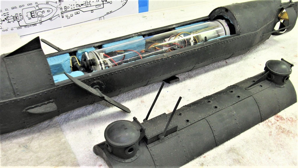
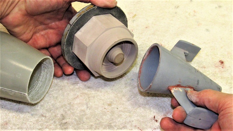
I liked how the original model-builder worked out access to the interior of the model. However, the watertight cylinder he provided to operate the r/c model submarine was pure amateur night! That will have to be replaced. As that WTC did not have a ballast tank -- the model presumably operated in the 'dynamic diving' mode -- I would have to come up with a WTC of my own, equipped with a proper ballast tank.
First thing was to gather the rather massive file I have on the HUNLEY, survey the model and determine what is fine as is and what has to be modified, replaced, or discarded. In order not to invest too much time with the project I would use the sharp knife; I'll get this thing working, but it will never be a museum piece.
The two big changes to the model would be installation of a propeller shaft pitching mechanism that would provide for positive control of the submarines pitch angle while running submerged. The second change would be abandonment of the incorrect bell-crank linkage that operated the rudder and substitute it with a torque-rod such as was employed by the real HUNLEY.
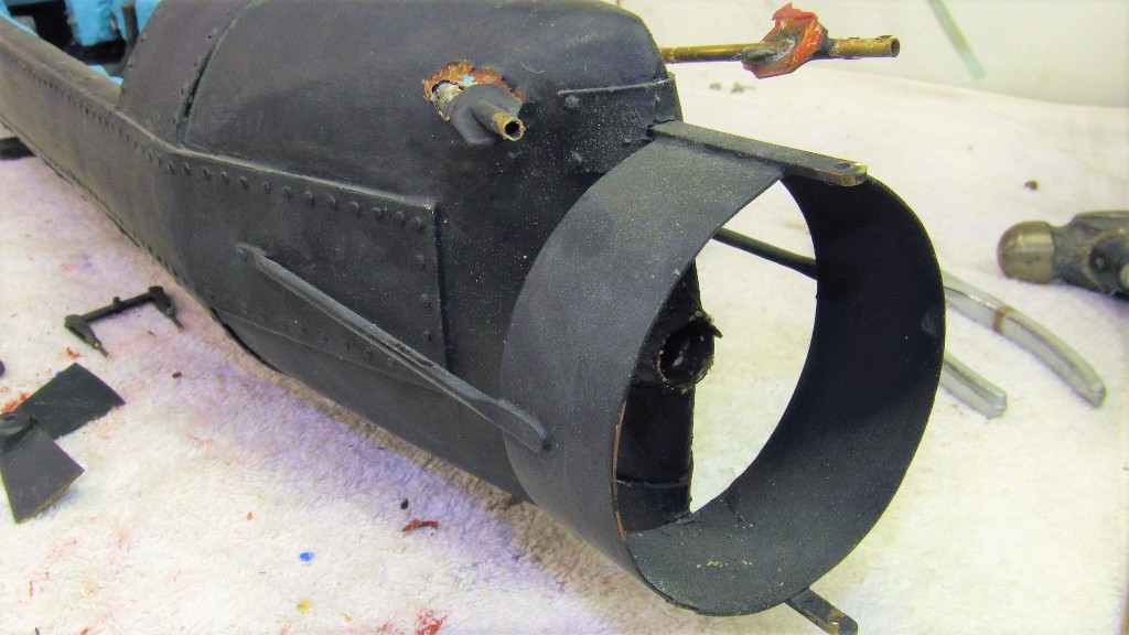
The rip out of rudder linkage and original running gear stern tube underway. The horror... The HORROR!
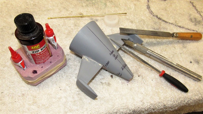
The propeller pitching mechanism started out as a simple doodle-sketch that was quickly brought to fruition at the lathe, milling machine, and with the aid of hand-tools. Machine brass is our friend! The original stuffing tube type stern tube was hammered out, the bore for the stern tube increased to accept a foundation tube, and within that would later be fitted a single axis gimbal that permits the propeller shaft to pitch up and down -- the resulting change in propeller thrust about the pitch axis would be the means of pitch control of the submerged submarine.
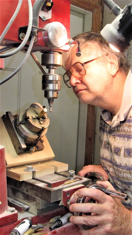
Here I'm boring out the gimbal housing of the pitch mechanism on the lathe.
Producing the oblong bore of the gimbal housing at the milling machine.
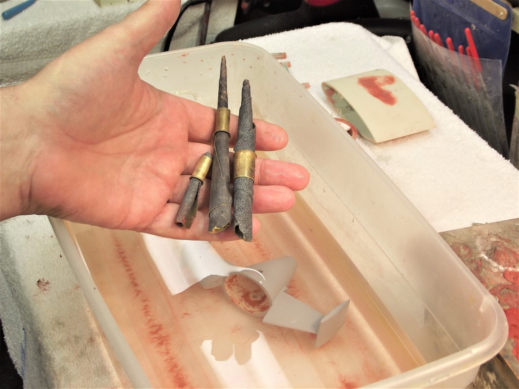
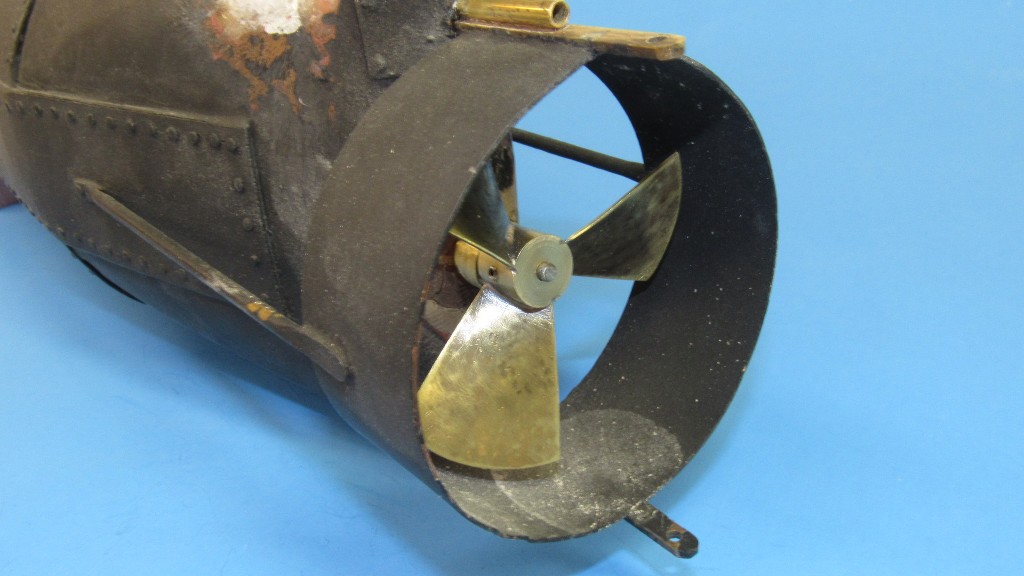
Two propellers came with the model HUNLEY. Neither was satisfactory or even close to the look of the real thing. So, I worked up a blade-chart for a practical wheel that would be more in keeping with the look of the real thing. Research is everything!
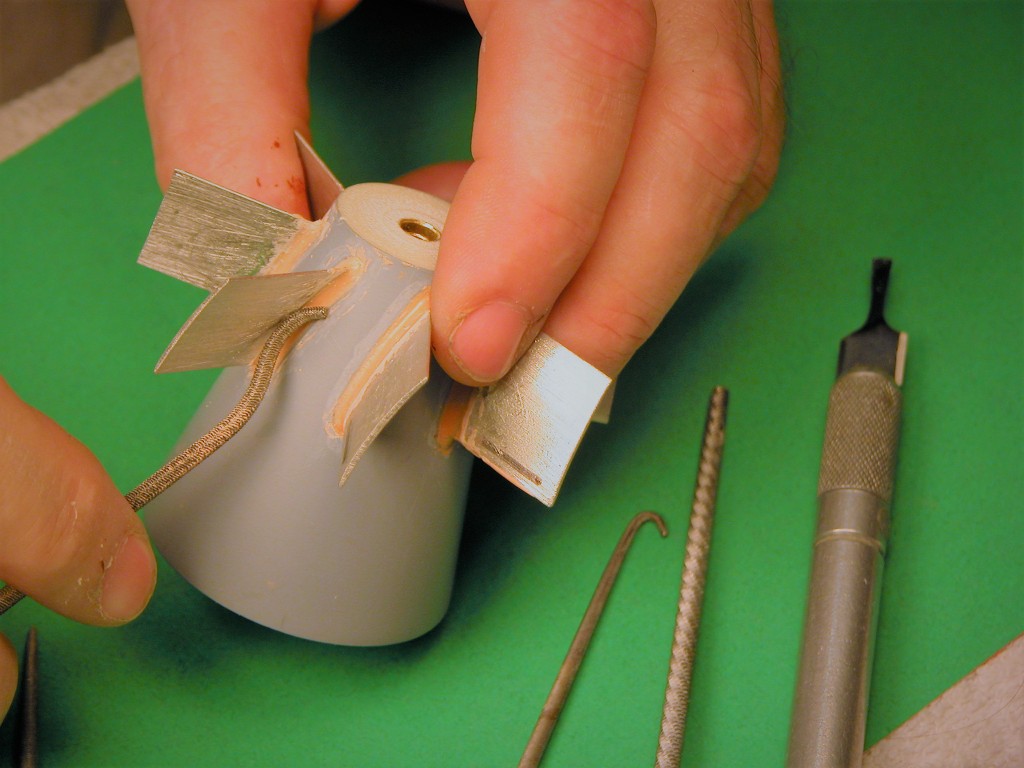
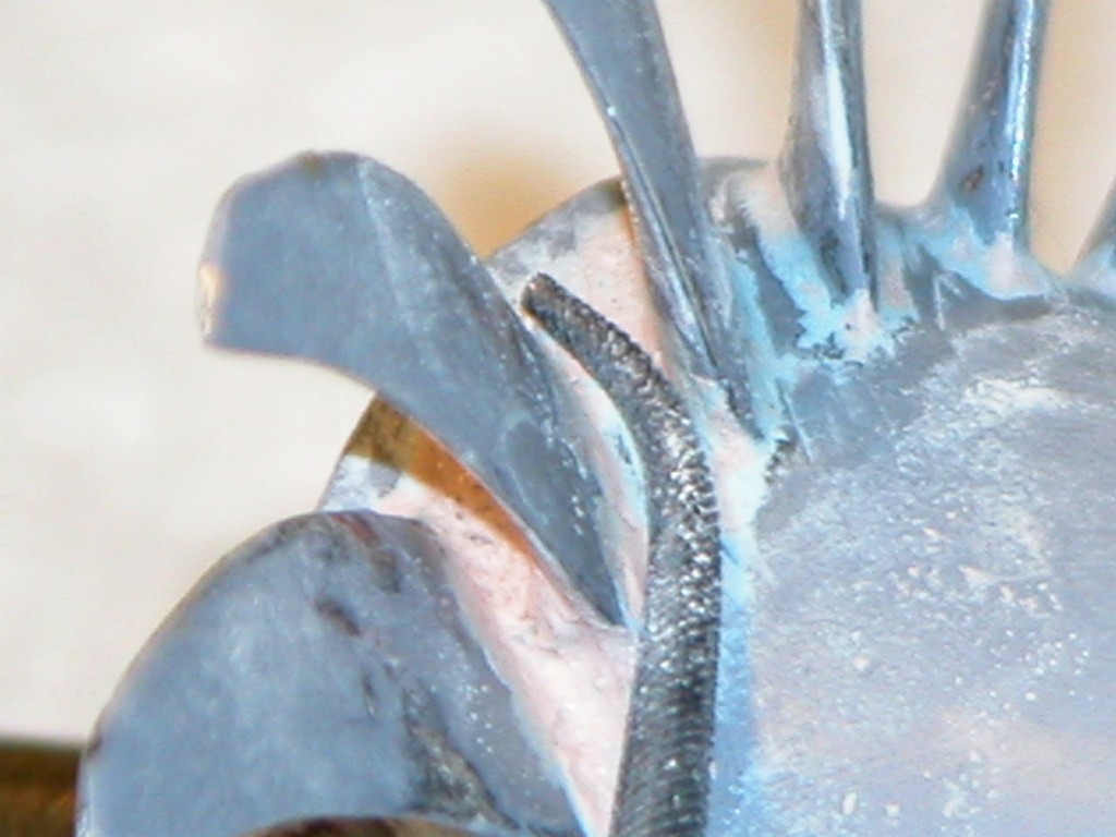
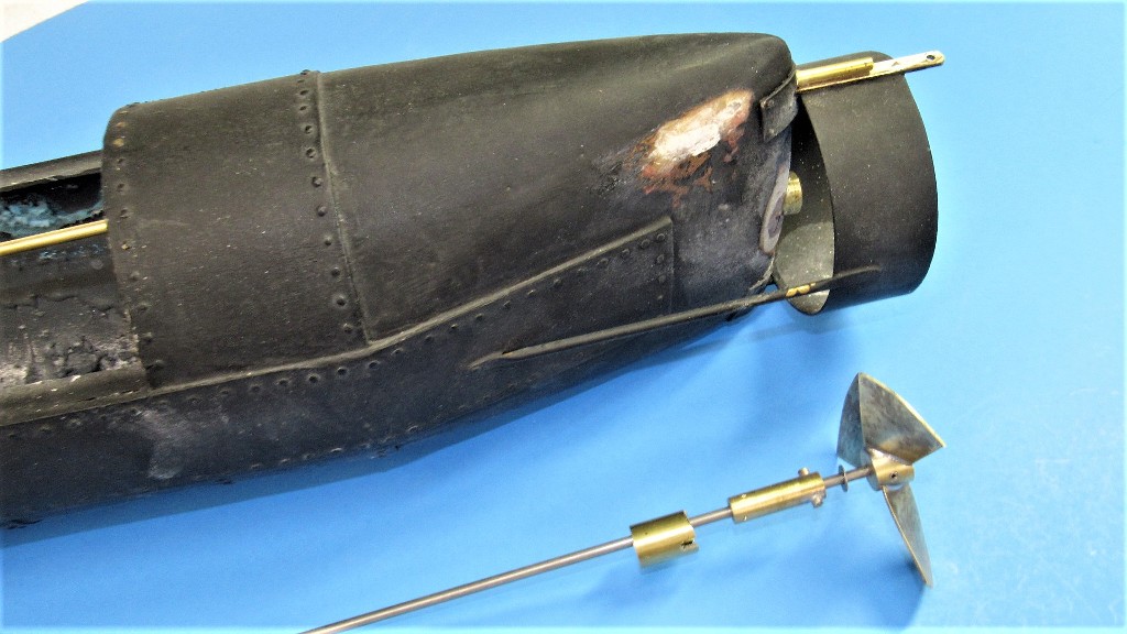
Got the propeller done and started to back-fit the proper torque-rod type rudder actuator -- got ride of the two pushrod-bell crank arrangement (an artifact from bum documentation that originated with one of the boats builders well after the event.
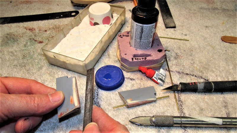
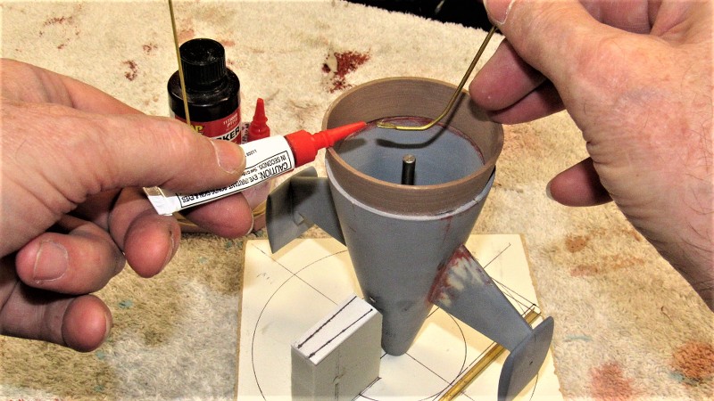
The rip-out of the two pushrods produced holes at the upper stern. These had to be filled, and most of that work was done with CA and baking soda.
The operation starts with a back-up of the hole from the inside -- wax paper if you want to be neat. A paper towel if you don't give a damn. While holding the back-up tight to block the hole from the inside, some baking soda is sprinkled on and thin formula CA applied, which instantly hardens. Repeat till the mass is higher than the surrounding structure. At that point the back-up is pulled out.
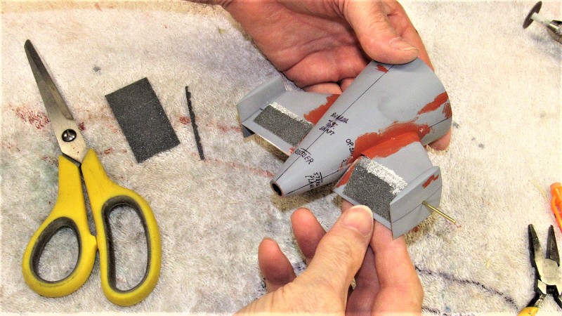
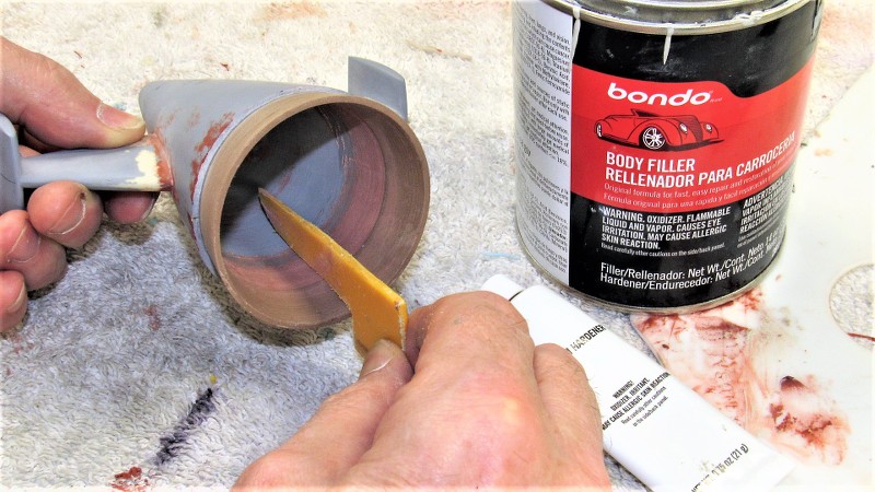
The mass is then ground down with a sanding drum followed by a course file, then sandpaper.
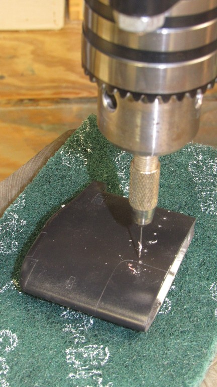
Drilling a hole to accept the rudder torque rod tube.
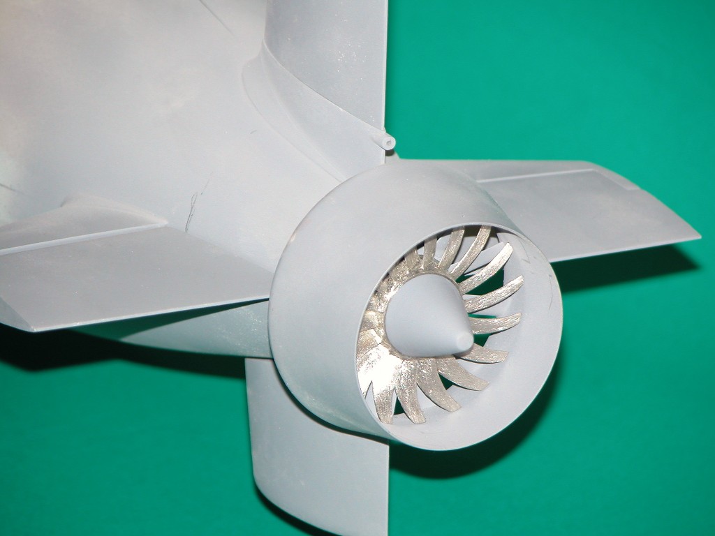
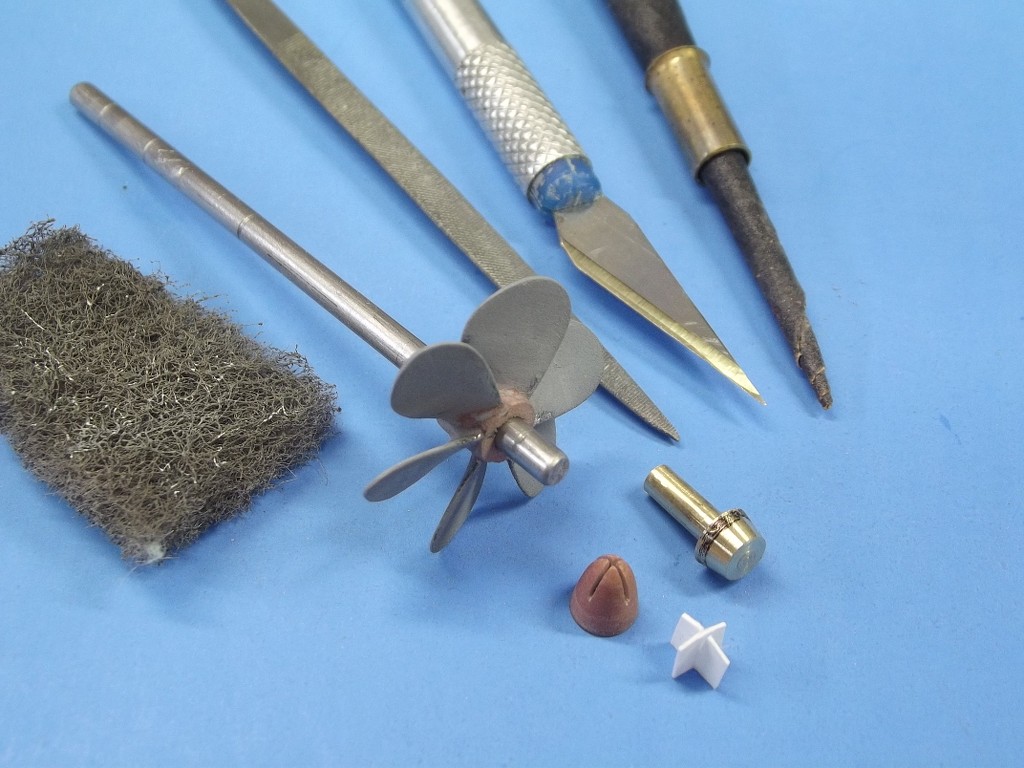
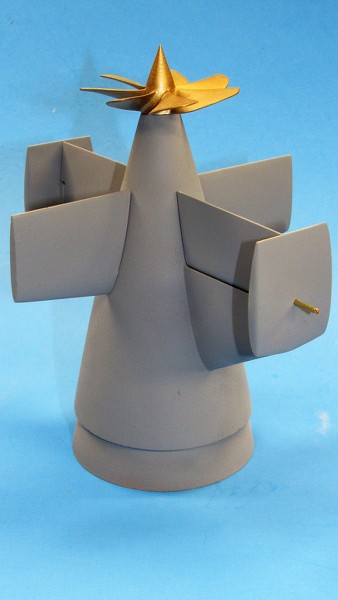
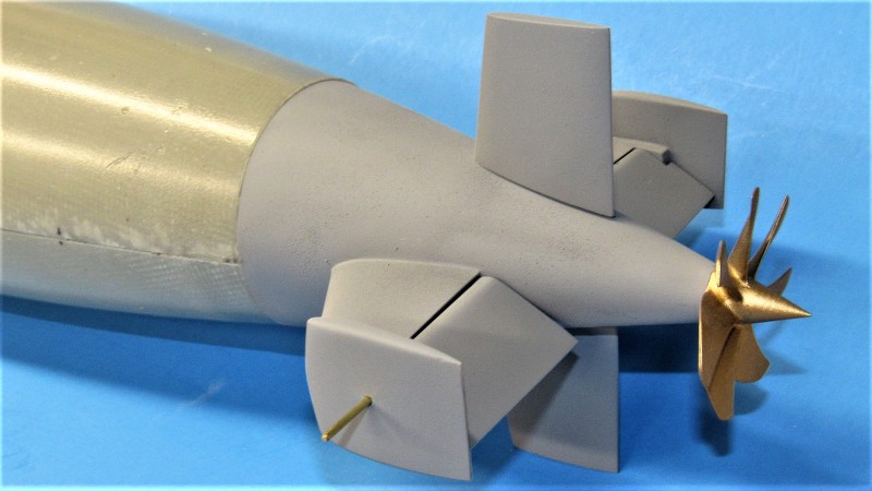
I'm jumping ahead a bit to show you the end-game: the completed propeller and pitch gimbal, all installed. The objective is to achieve positive control of the boats pitch-angle while submerged through the use of active thrust vectoring -- tilting the propeller up and down will produce the torque needed to keep the boat on a near zero bubble angle.
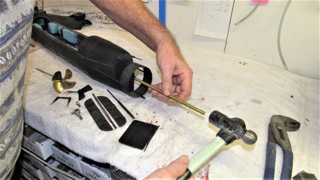
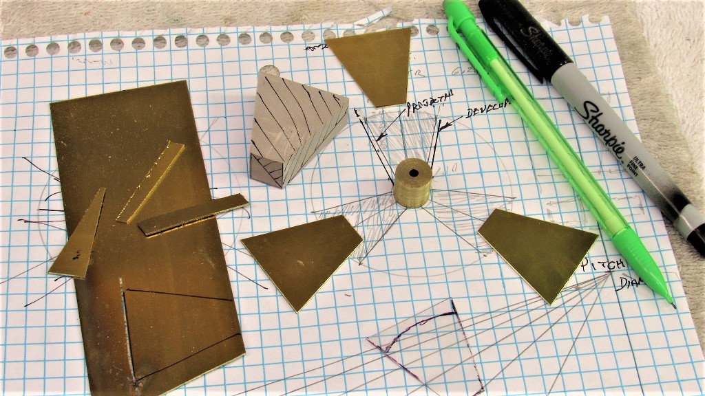
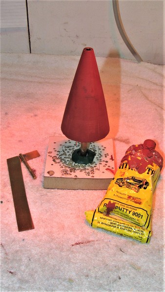
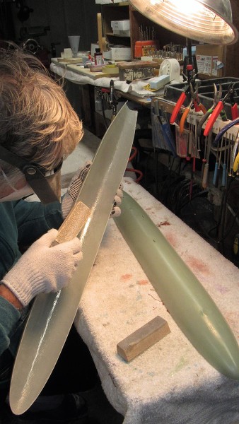
From .030" thick sheet brass I cut out three propeller blade blanks. Then, from dense RenShape, I carved out a blade pitch mandrel that would be used to form the annealed blades to the correct helical twist demanded by the blade-chart.
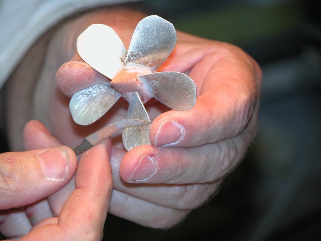
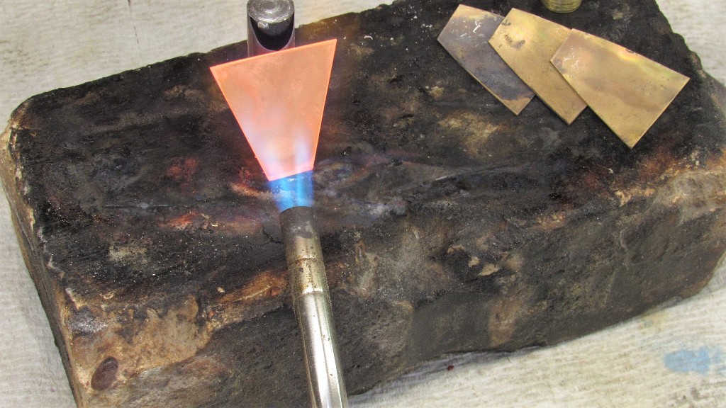
The cartridge brass is much too stiff to bend easily, so it it taken to a red heat and allowed to cool back to room temperature without quenching. The softened propeller blades are now malleable enough to be easily bent to the required twist by hand and light hammering over the mandrel. (if you look carefully you can just make out Exeter's image on the view screen as it cools... joking!).
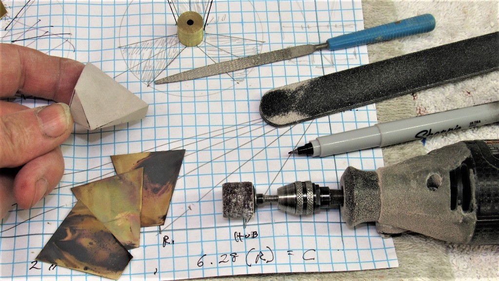
Here I've ground, filed, and sanded the helical twist into the blade forming mandrel. The oxidation on the blade blanks is a consequence of the heat treatment and is later abraded away after the blades are formed, and soldered to their solid brass hub.
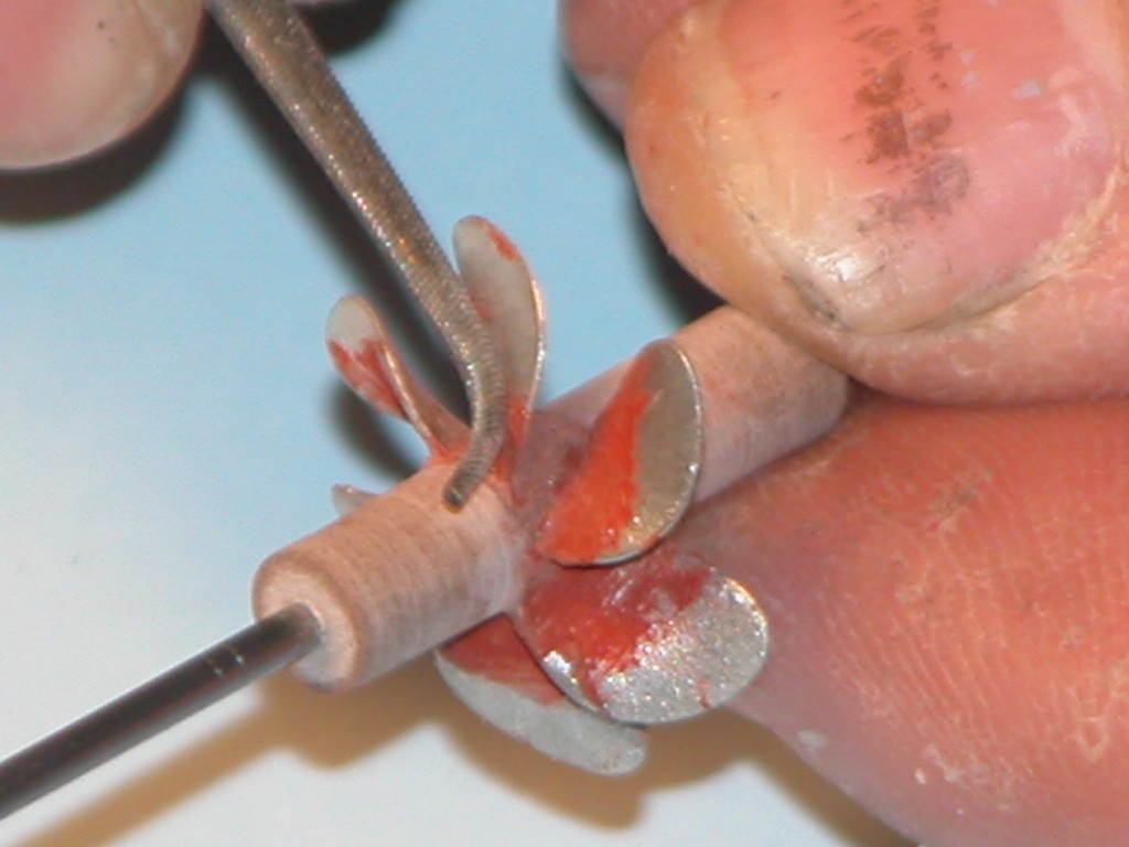
Most twisting of the blades was done between thumbs and forefingers. The final work was done with repeated light hammer blows with the work sitting on the face of the mandrel. The mandrel was temporarily glued atop an anvil. The constant hammering 'work hardened' the blades, making them stiff enough to handle and assemble without fear of accidently bending them out of shape.
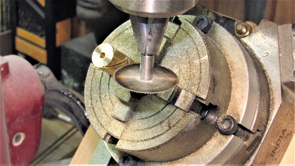
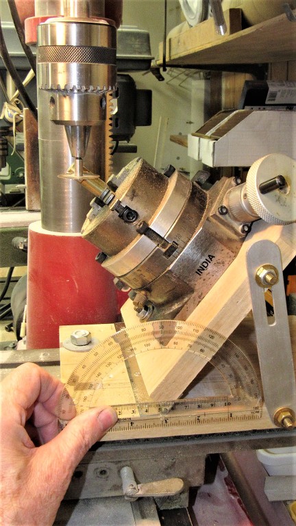
Three slits were cut into the solid brass hub to receive the propeller blades. A rotary table, angled to the saw to produce the correct blade-hub interface slits. As the rotary table is indexed it was an easy matter to dial in the three equally spaced slits.
I love my cheap-ass Chinese milling machine, but sometimes (like here) I wish I had sprung for a proper Bridgeport machine with the ability to tilt the spindle-head instead of having to jury-rig this Rube Goldberg fixture to angle the rotary table to the saw. Oh, well.
From the blade-chart I was informed that the angle at the hub where the root of the blades fit is 55-degrees. So be it -- I hear and obey!
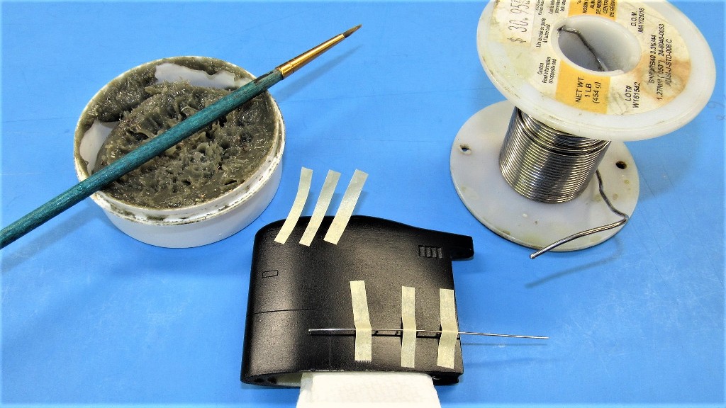
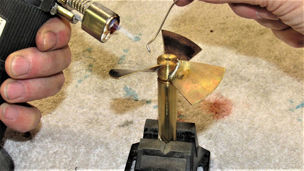
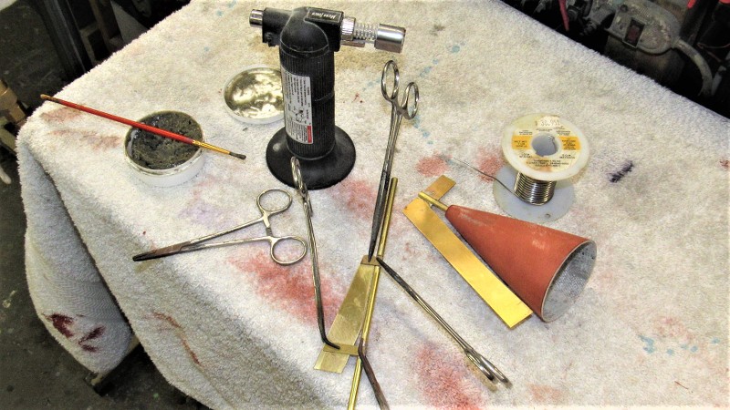
The blade roots were a tight fit to the hub slits so there was no need for a holding fixture as the blades were soldered in place. Friction is our friend! Here I'm slathering on some acid flux to insure a nice clean, strong wetting of the metal as the molten solder is applied.
60-40 solder is fine for this kind of work -- plenty of adhesive area, buttressed with heavy fillets. The soldering operation only took seconds to perform. Soldering is adhesion, not welding; it's glue, boy's and girls.
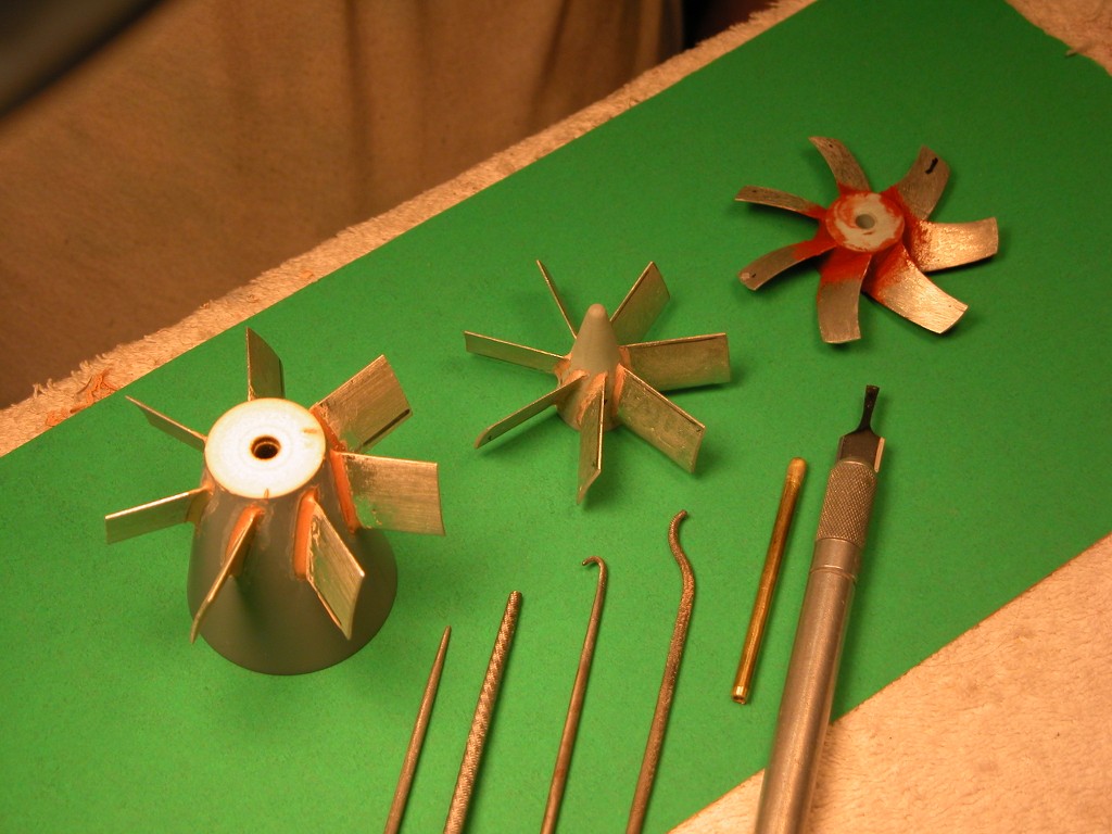
Files, sandpaper, and a rotary wire brush cleaned up the assembled propeller.
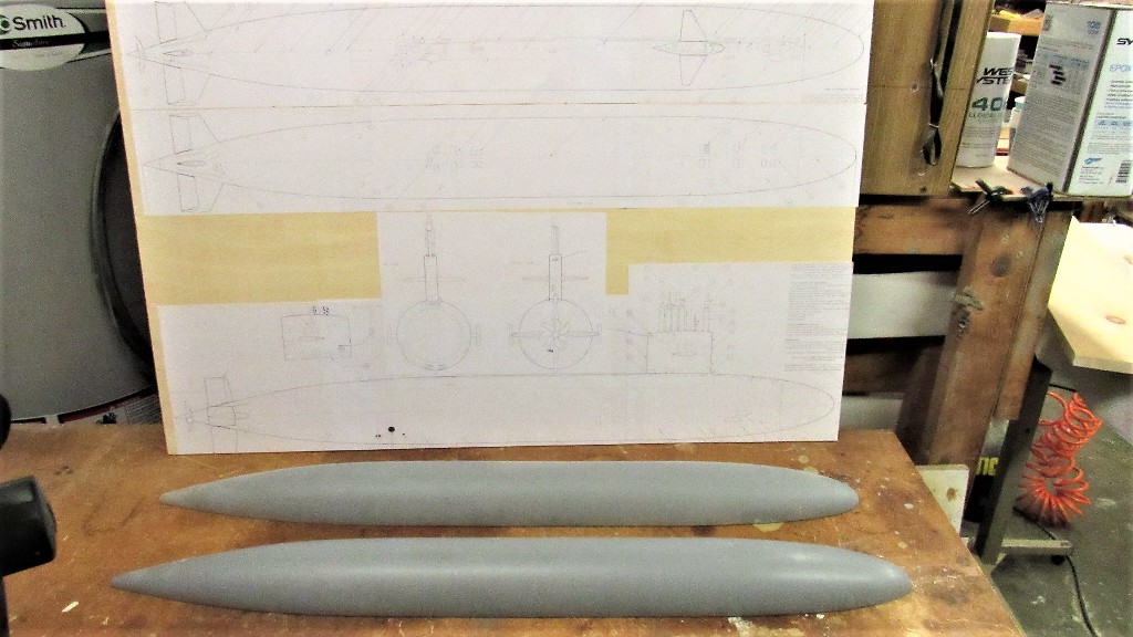
I'm currently engaged in creation of tooling that will be used to produce GRP (fiberglass) hull and resin and metal parts of a 1/96 scale kit of the American STURGEON class attack submarine. Most of the masters I'm handling here were created by Matthew Thor who sold them to Nautilus Drydocks, an outfit I've been affiliated with for a number of years now.
Details concerning the STURGEON and the other thirty-six boats of the class can be found here: Sturgeon-class submarine - Wikipedia
The quality of the masters I received were, for the most part, exceptional in regards to their scale fidelity and craftsmanship; very, very good work.
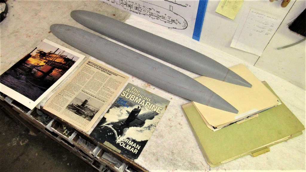
However, there were a few problem areas that had to be addressed before using them to produce the tooling. As research is everything when dealing with scale models, I took pains to study my files and external sources – the objective was to create masters that would depict the first 'short hull' boats of the class. I leave it to future customers of the kit to make the appropriate modifications needed to configure their model to suit the characteristics of a specific boat they wish to represent in miniature. I only supply the canvas, not the paint.
The principle document I used to further detail the STURGEON masters was a 1/96 scale, five-view orthographic drawing produced by the famed Canadian r/c submariner, Greg Sharpe. His work lofted off official documents. I consider them source material. Someone correct me... I dare you!
Buttressing the drawings were hundreds of photos and other documents I've been collecting the last forty years.
There are two schools of thought as to how tooling intended for GRP production should be made.
One is the 'hard-shell' type mold – typically a stiff GRP lay-up over the master. This type has the virtue of being simple and cheap to produce. The drawback to this type tool is the need to avoid deep draft items; the master has to be compromised as to depth of engraved lines in order to prevent entrapment of the master (and later the GRP part produced) within the tool that gave it form.
Any significant depth of engravings invariably leads to tool damage during the extraction process. You just can't get the level of engraved and/or high relief detailing into a hard-shell tool than you can with a rubber tool. Also, the hard-shell tool is most unforgiving if you fail to correctly apply the correct type mold-release system between lay-up cycles – get it wrong and you trash the tool!
The resulting GRP hull part produced in the hard-shell tool will capture engraved lines, yes, but by necessity the depth of those engraved lines must be shallow and unreasonably wide. The result is engraved detail that is not deep or narrow enough to throw significantly stark shadows, greatly reducing the visual impact of the engravings.
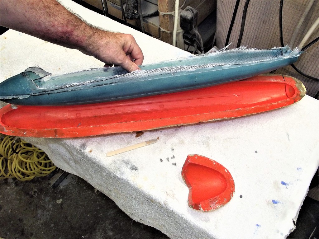
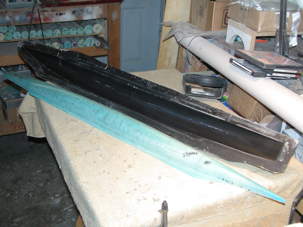
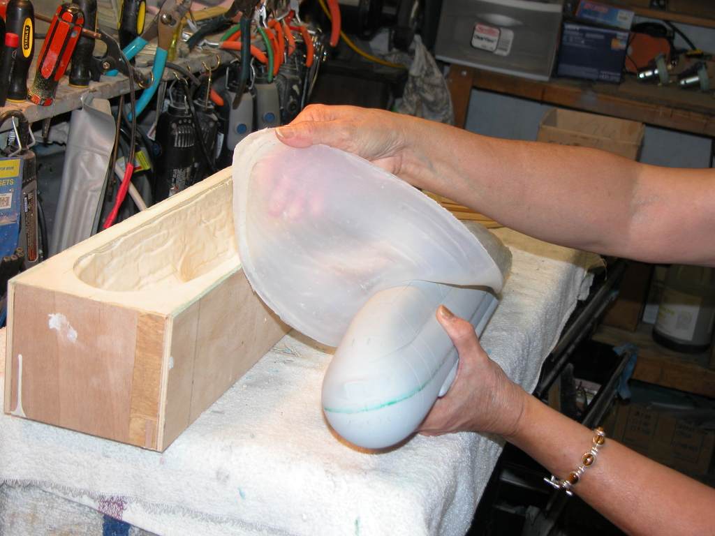
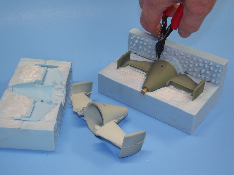
The preferred tool is of the compound type, made up of two elements: a flexible rubber glove-mold, backed by a stiff mother-mold. This type, owing to the flexible nature of the rubber glove has no problem separating from the master and later production parts regardless of draft depth or angle – this type tool will easily pull away from parts of negative draft without damage or wear. Such as this 1/96 THRESHER hull tool.
Once the GRP has been laid up in the rubber glove, the glove is pulled away from its backing mother-mold and peeled – like a glove – away from the GRP part. No matter the engraved or high-relief items unique to the subject, the glove nor the part is damaged during the de-molding process. Pretty damned slick!
All that needs to be done is to re-seat the glove into the mother-mold, spray on a few coats of poly vinyl alcohol, and you're ready to start another GRP lay-up. No waxing, no buffing, no bull-shit.
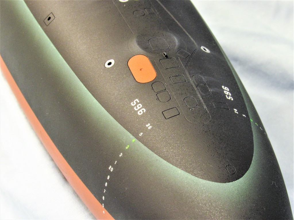
The result of the mother-glove type tool are deep, crisp, narrow engravings. The bow of this completed 1/96 THRESHER class model, formed in such a tool, so demonstrates. Compare the engravings on this model to those on the hull produced in a hard-shell type tool. A world of difference.
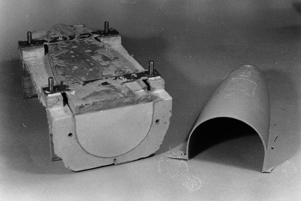
The two STURGEON hull masters – an upper half, and a lower half – were mounted on a mold-board. The flat face of the mold-board would later form the parting flange shared by the hard and rubber faces of the compound tool. One tool for the upper hull, one tool for the lower hull.
Each hull master was secured to its mold-board with the aid of three deck-screws passed up through the bottom of the mold-board.
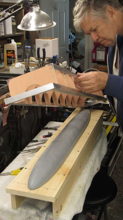
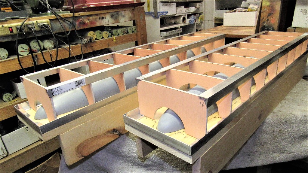
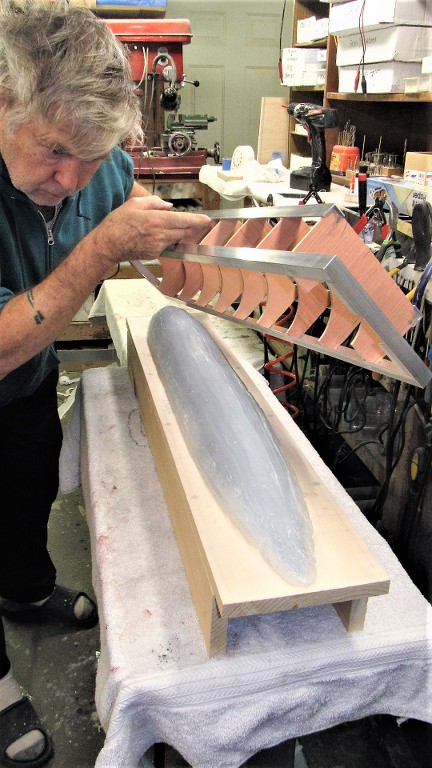
Most of the STURGEON hull tooling work involves building the support structure for the eventual mother-mold element of the tool. These structures, called 'egg-crating', provide a stable support for and convenient table upon which the inverted tools cavity is accessed for part glass lay-up. The egg-crating only goes onto the mold board after the rubber glove has been built up over the hull master and over that the first layers of mother-mold tooling resin applied. Eventually the tooling resin will bond to the ribs of the egg-crate forming the ridgid and easy to handle assembly.
Enhancement of the hull masters included inclusion of a radial engraved line near the stern. This will denote, on the GRP hull parts, where to cut away the end of the assembled hull to make way for a hollow cast resin stern cone that will come complete with attached horizontal stabilizers, stern tube and bearing, and rudder and stern plane interconnecting yokes. Good kit engineering strives to produce a product any mouth-breathing idiot can assemble with the minimum of fuss.
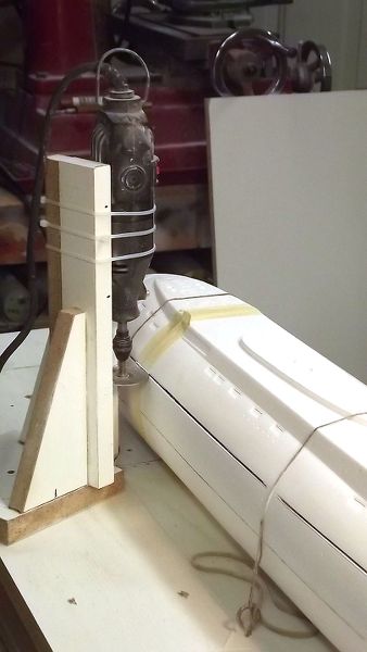
A vertical fence was temporarily screwed in place over the mold board to permit use of a waterline marking tool to lay off a radial pencil line onto the stern of a master. I would later remove the master from the mold-board and with careful use of a razor saw I would engrave a very shallow, narrow cheat-line.
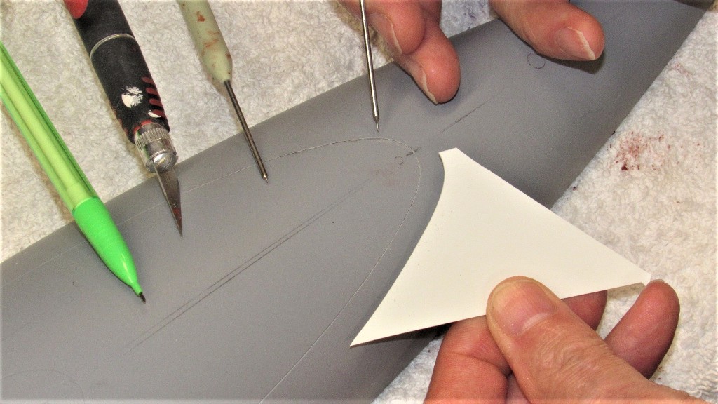
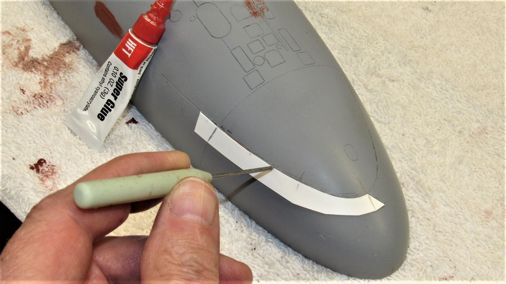
The one major fault with the Thor STURGEON hull master we received (I suspect there are more than one set of 'masters' out there) was the height of the two escape trunk hatch 'flats'. Instead of the plane of the flat being flush with the top of the hull the flats stood .040” over deck level. That had to be fixed. Fortunately this portion of the master was a cylinder of easily ground, scribed and filed plastic rod. After that work the deck hatch outline was re-scribed
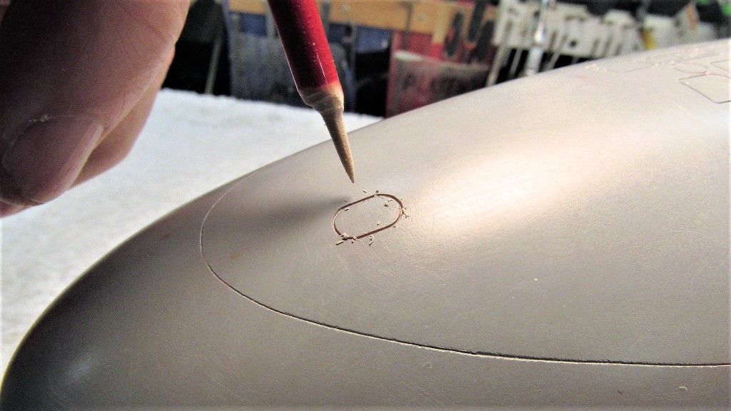
Once the two escape trunk flats had been taken to deck level I ran a length of pencil 'lead' over the hull – the fragile lead strengthened by gluing it to a scrap piece of plastic sheet that also served as a handle. Resting a portion of the lead on the circular rim of a flat I circled it around to that the outboard portion of lead contacted the hull, denoting where the eventual fairing between flat and hull took place.
I set about the work of fairing the outboard areas between circular flat and gentile compound curve of the hull. I'm showing the work at the bow, but the same job had to be performed as I worked the engine room escape trunk hatch flat as well.
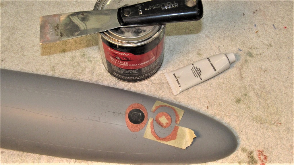
A mask was prepared to confine the Bondo to only those ares on the hull where there would be a fairing. Those masks went a long way in reducing the work involved in filing and sanding the Bondo to shape.
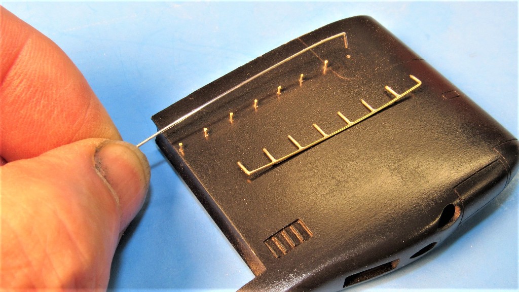
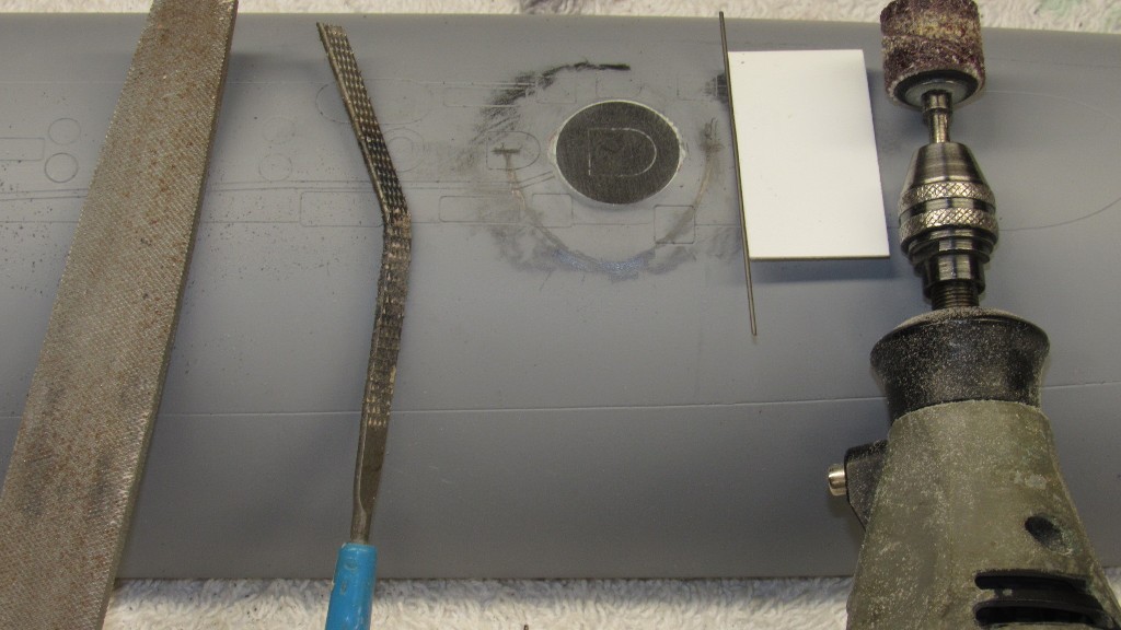
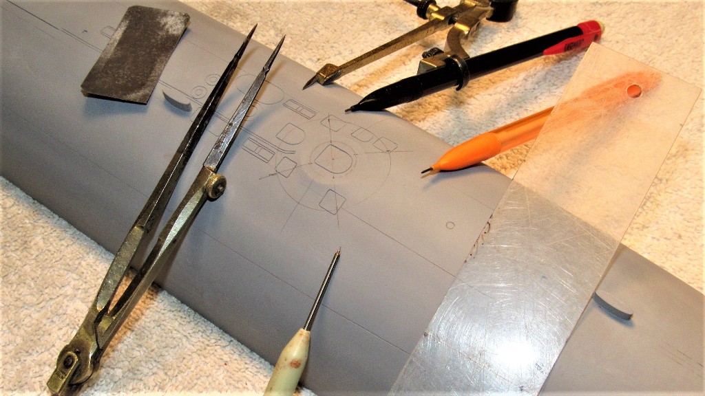
The second major chore was to deepen – and in only a few instances, correct – engraved lines that denoted access hatches, line lockers, capstans, main ballast tank vents, salvage plates, buoy markers, reversible cleats, bull-nose, torpedo tube shutters, ballast tank flood-drains, anchor, main and auxiliary sea water penetrations; and portions of safety-track.
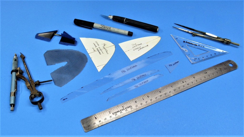
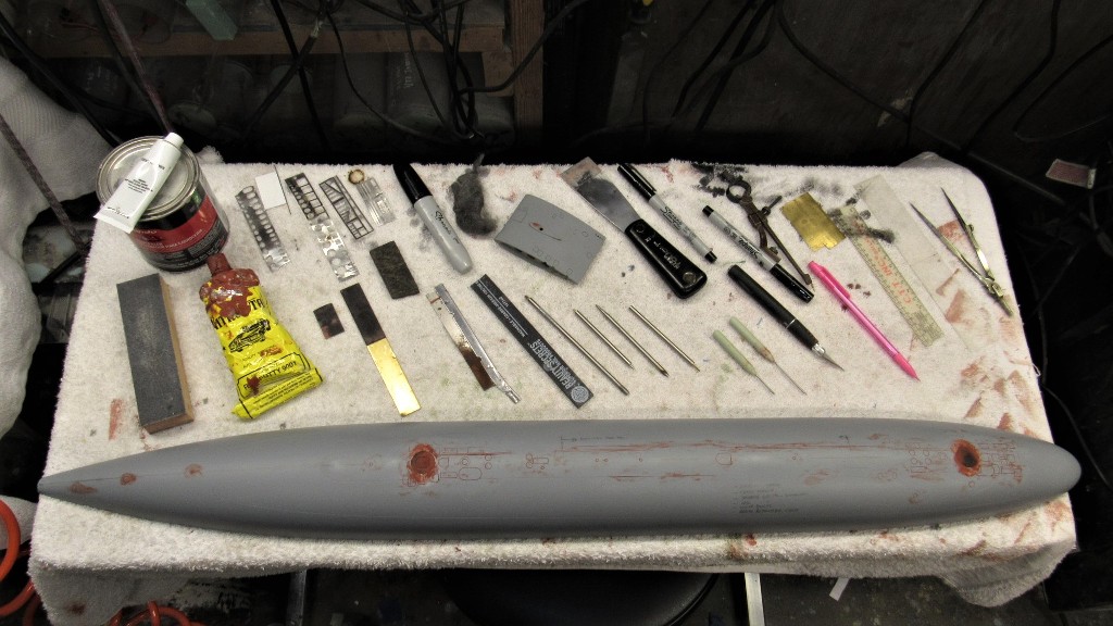
What a job the engraving enhancement turned out to be! You see here just some of the stencils, engraving scratch-awls, abrasives, fillers and putties, files, and measuring tools required for the work.
These masters, apparently, were intended for creation of hard-shell type tools. But, as I was going to produce a proper set of glove-mother molds intended to capture deeper engravings and significantly raised details (not present on the masters as delivered), I was compelled to deepen the existing engraved lines and add those appendages.
When I took on the job I assumed that that hull master halves were wood, but was delighted to find that it was a GRP copy. Not the original pattern. So. Are there more than one set of Thor 'masters' out there we don't know about?? Not my problem … I'm only the idiot model-builder with a job to do. The proprietary aspects of this property are not my concern.
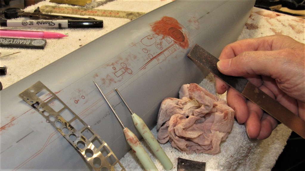
Any way, it was a relatively easy matter to deepen the engraved lines in a GRP substrate than it would have been had the underlying material been wood. I was grateful for that. Inevitably, as I worked the engraving with scratch-awl and razor saw I invariably buggered up some of the work with over-strikes and miss-directed passes. I would work a section then lay down some air-dry putty, chasing out the properly engraved lines before the putty could dry thoroughly. After sanding, what was left were deepened, narrow of width engraved lines.
Special sanding tools were employed -- specifically brass strips with #400 glued to one face and #600 to the other – to insure only the puttied areas were knocked down as I wet sanded the dried putty. Particular care was taken on the escape trunk flats and surrounding fairing.
Once happy with a section of the hull, I applied a light coat of gray primer. Repeating the examination-putty-sanding-priming steps as many times as required.
Additional scribing included enhancement of a cheat line for the anti-foul boarder on the deck, as well as the designed waterline had to be completed forward of the sonar dome radial line – that radial line can't be seen in any photos of the real boats, so I softened it with putty.
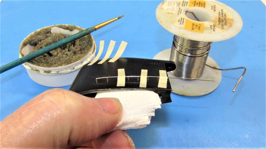
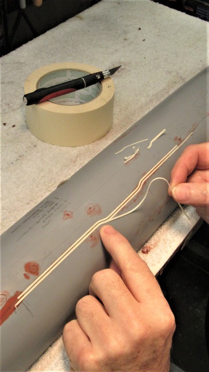
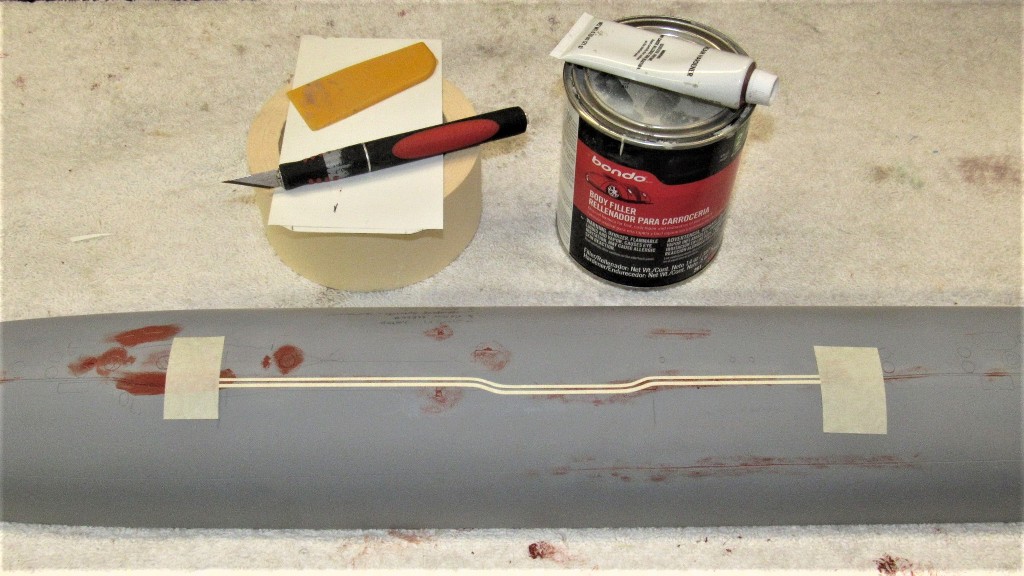
The master did not represent the raised portion of safety-track welded atop the pressure hull portions of the submarine. I built the raised portions of track from Bondo between three plys of masking tape. Making the masking strips narrow gave them the flexibility to negotiate the tight radius jogs you see here:
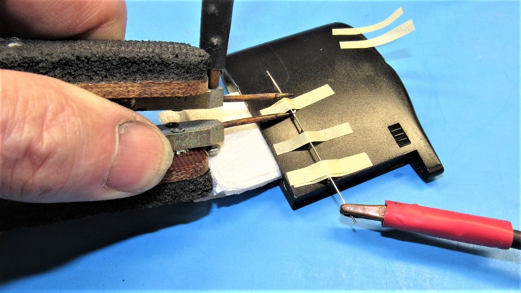
A small amount of Bondo was catalyzed and screed between the two parallel masks.
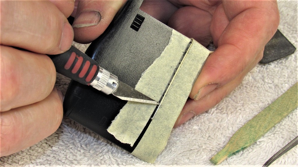
Before removing the masking the top of the Bondo safety-track was coated with thin formula CA to strengthen the porous Bondo. The masking was removed and a little work with file and sandpaper, and the safety-track was done.
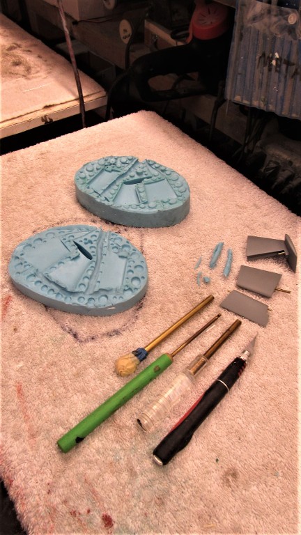
Three hydrophones are prominently displayed sitting atop the hull on most units of the STURGEON class submarine. These items would be impractical protuberances on a master used to create a hard-shell type tool, but are a welcome enhancement when captured faithfully and without fear of entrapment when giving form to a glove type mold. These items were formed from 40 lbs. RenShape pattern making medium and glued to the deck of the hull master.
Along the deck of a STURGEON class submarine are situated brackets that stand slightly proud of the hull, these foundations accept and make fast to the hull 'portable cleats' used to secure mooring lines between ship and pier – these heavy, hard to hold toe-crushers had to be shipped up and down the escape trunk ladders every maneuvering watch. Total nightmares for the deck gang I heard.
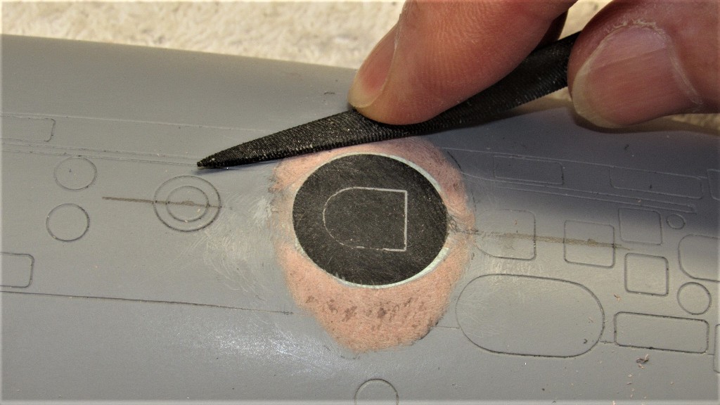
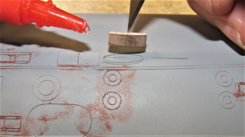
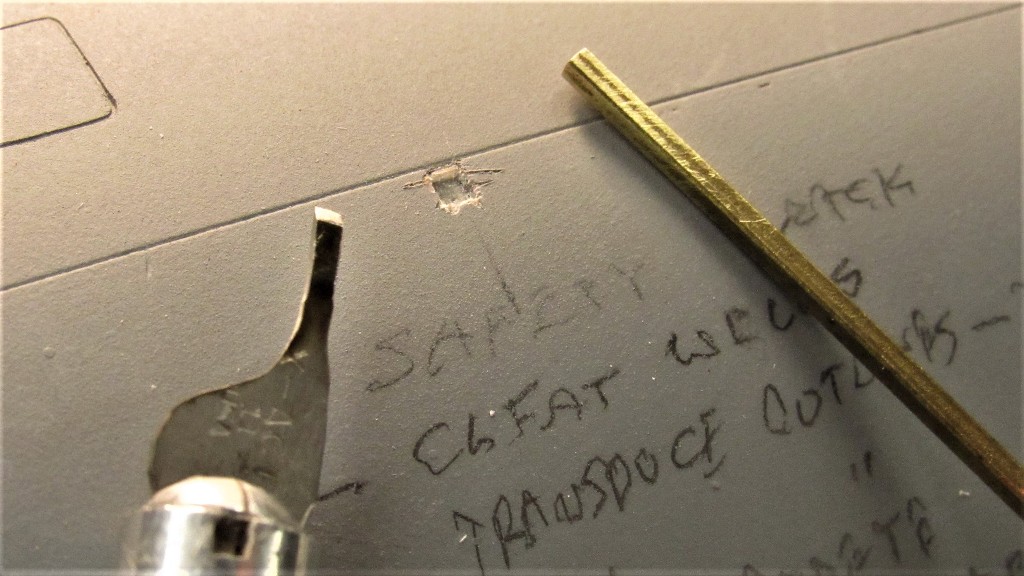
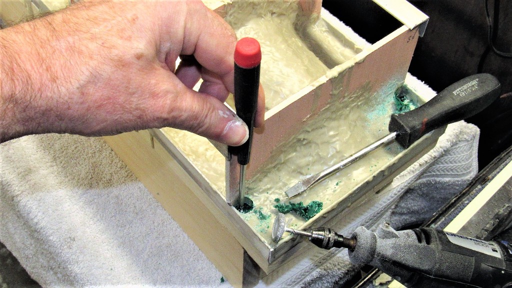
Square indentations in the hull master would impart the same to the eventual model parts. Cast metal brackets would fit those hulls during model assembly.
I first drilled then gouged out rough square holes, then back filled these depressions with Bondo and before that hardened I placed a square tube in the depression to refine its square shape. The form removed once the filler had hardened. Saliva, as it turns out, is a fine part-release!
The hull masters are just about done. Now to rub down a few layers of mold-release wax, mount the masters to their respective mold-boards, and to start laying down repeated layers of brushable RTV mold making rubber to form the glove-mold.
One last detail item I put to the upper hull master was little indentations around the two escape trunk hatches -- these cheat-marks denote were little holes will be drilled into the eventual GRP hull to accept padeyes. These representing hard-points used by the McCain Rescue Bell hold down turnbuckles during a crew rescue operation.
Incidentally, the STURGEON class boats were the last American combatants configured with marker buoys and hold-down padeyes. From LOS ANGELES on all American submarines would rely on the DSRV system to rescue a crew on a stranded boat. Guess, what, sports-fans?... We don't have DSRV's anymore. WTF?!
Before mounting the two hull half masters to their mold-boards I first laid shown a sheet of parchment paper between the base of each master and the face of the mold-board -- this to keep the very sticky glove making rubber from sticking too tightly to the mold board.
I used a pen loaded compass to mark off a stand-off between base of a hull master and where I wanted the eventual build up of RTV glove rubber to stop.
I waxed the masters to insure a clean, easy parting of the eventual RTV glove mold when the time came. I've made gloves without the wax without any stick problems, but I'm getting ever more conservative and careful with old age.
After rubbing the wax into the work I used a sharpened dowel to chase out wax from all the engravings.
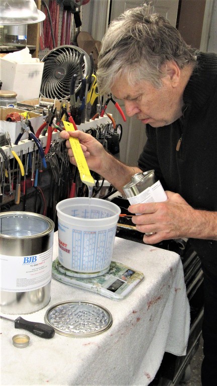
And finally starting to lay down the, what will be many, layers of 'brushable' RTV mold making rubber.
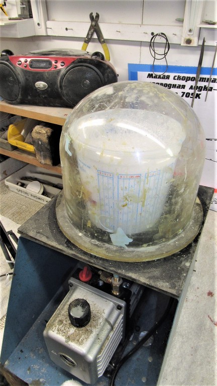
The catalyzed rubber has to be mixed thoroughly, which folds in a lot of big air-bubbles. These have to be eliminated before application by subjecting the mix to a hard vacuum.
Something I failed to mention was my use of two heat-lamps to accelerate the cure of the glove-mold rubber. As Winter is on us and the shop is correspondingly cooler I found it necessary to keep heat on the work if I was to get all the work done in a reasonable amount of time.
Duplicate items on the submarine -- fairwater planes, stern planes, and horizontal-vertical stabilizers -- were not provided, only one each. No problem as each item is a mirror of its eventual doppelganger. So, I made a rubber tool off the three provided masters and would, later, cast two production masters of each item.
A mold-board for this quick and dirty resin casting tool was cut out from an old strong-back. This would be a platform over which I would lay down a thick mask of oil based clay.
The mask permits only one-half of a master to be covered by the RTV rubber that forms the first half of a two-piece tool.
A masking tape dam was wrapped around the clay and catalyzed RTV rubber poured in to cover the masters. Note that I've indexed the face of the clay -- which forms the interface flange between the two eventual tool halves -- with dimples. These keys would insure correct registration of the two tool halves later.
I used an entire one-gallon kit of TC-5040 RTV mold making rubber to form the glove. This resulted in the desired nominal wall thickness of about 1/2". Next move was to pop the two half-hull masters, now coated with thick gloves, off the mold-boards, trim away excess rubber from the flanges, and to prepare things for creation of the hard-shell mother-molds that would interface with the glove and provide the floppy rubber with a firm foundation.
Each hull master was unscrewed from its mold-board and removed. Inverting the masters with the Parchment paper facing me -- which had been previously inked as to the desired thickness of the glove to guide me as I knifed away excessive rubber from the base of the glove. The glove remains attached to the master. The parchment paper was stripped away, and the mold-board readied for re-attachment of the masters with attached gloves.
To assure that the eventual interface between glove and mother was firm I punched out vertical groves to the sides of the glove flange.
I laid down a fresh parchment, secured the masters to the mold-boards, waxed the gloves and parchment paper, made up the egg-crate support structures, and I was ready to mix up and brush on the tool making resin that would give form to the hard-shell mother-mold.
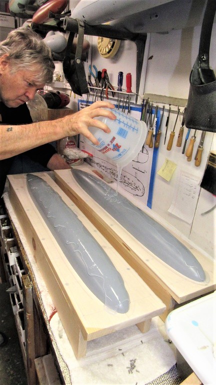
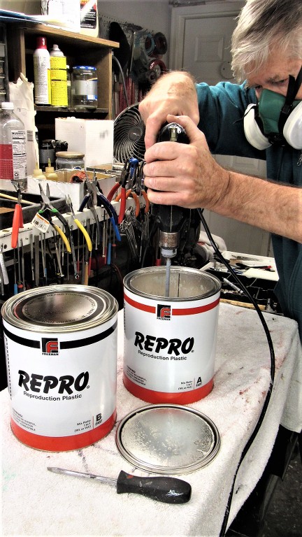
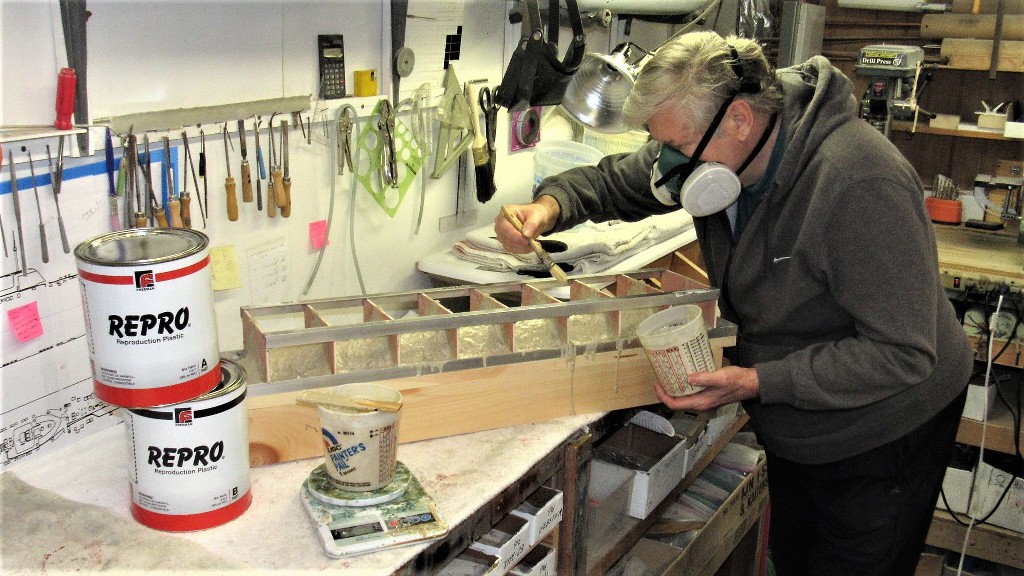
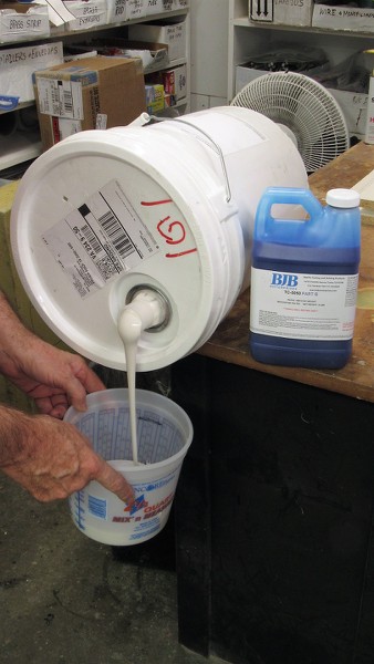
The mother-mold was manufactured by brushing a special polyurethane 'tool making' resin, available from Freeman Pattern Supply Company. I use the Repro brand. This quick-cure, two-part resin is brushed over both the just completed rubber glove-mold and also saturates the bed of the egg-crate support structure as well as all the transverse re-enforcing frames of the structure. The shell formed becomes a rigid, perfect fit to the rubber glove under it.
As it turned out, the most labor intensive part of the mother-mold fabrication was mixing the A and B sides of the goo that would harden into the shell. Thank god for jiffy-mixers and drill motor!
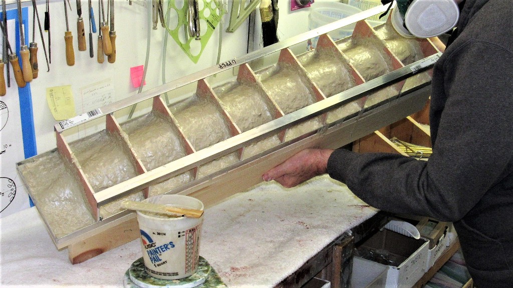
After screwing down the egg-crate down tight onto the mold-board I took the precaution of covering the screw heads with clay. This would later permit me to easily access these screws when it came time to lift the mother mold off the glove-mold. Here I'm brushing on one of the five thick coats of tooling resin
The first coat went on neat. All subsequent coats were mixed with fiberglass shards for strength an to prevent sagging of the still liquid resin. The work went very quickly as the pot life was about ten minutes and the stuff would harden enough to permit another coat in only twenty-minutes. Great stuff, and it eventually cures to rock hard.
Digging away some of the mother-mold shell to access the six screws that secured the mother-mold assemble to the face of the mold-board.
To pop the completed mother-mold assembly away from the underlying rubber glove I used air pressure. I ground away a hole through the mother-mold, stopping when I hit rubber. A quick blast of air and the mother mold jumped off the rubber glove it had been lightly adhered to.
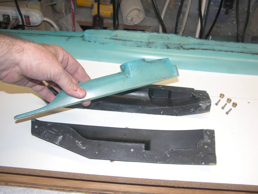
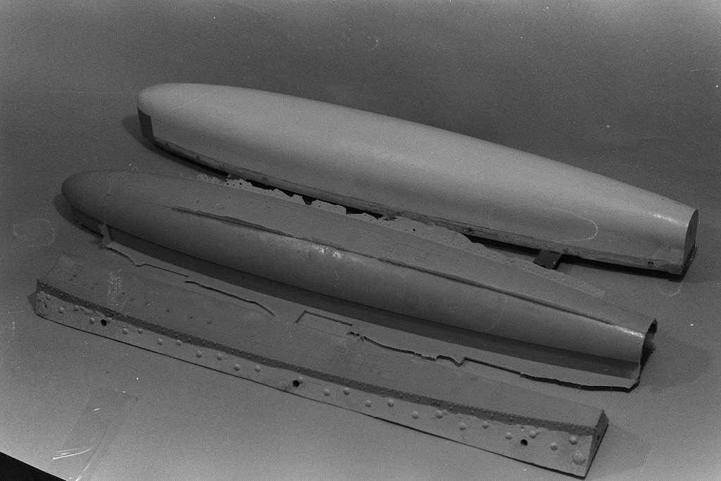
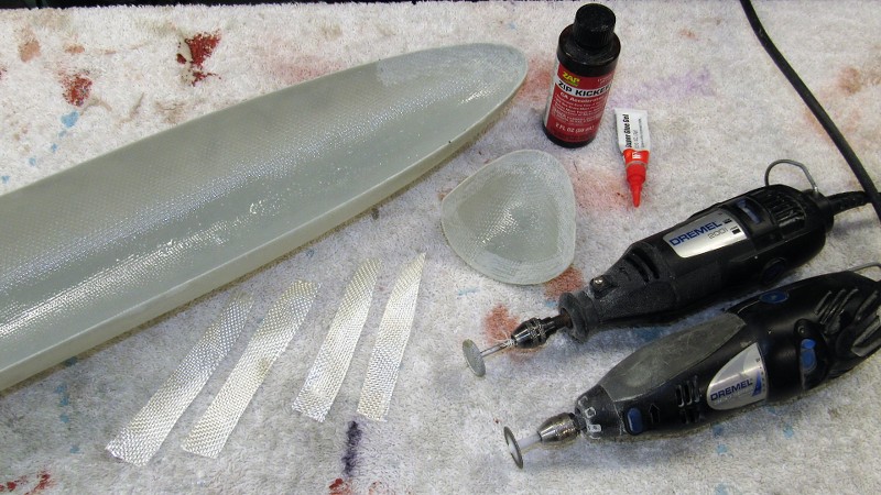
I assembled the tools and set about laying up what would become the master of a complete tail-cone assembly complete with horizontal and vertical stabilizers, stern tube and forward radial flange. That master started life as a fiberglass layup as illustrated here.
I still make use of other peoples hard-shell tools to produce product.
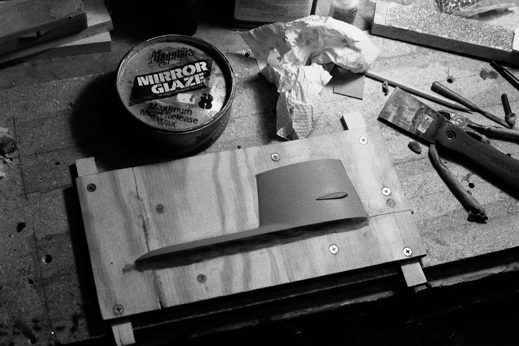
I believe the last hard-shell GRP production tool I produced was back in the mid-90's: an early effort at some production tooling for our SKIPJACK kit, specifically, the sail. Here you see the master on its mold board about to be built up upon by layers of glass cloth and resin to form the hard-shell tool. And the completed tool used to produce production GRP sail parts. I have since converted to a rubber tool from which resin sails are produced.
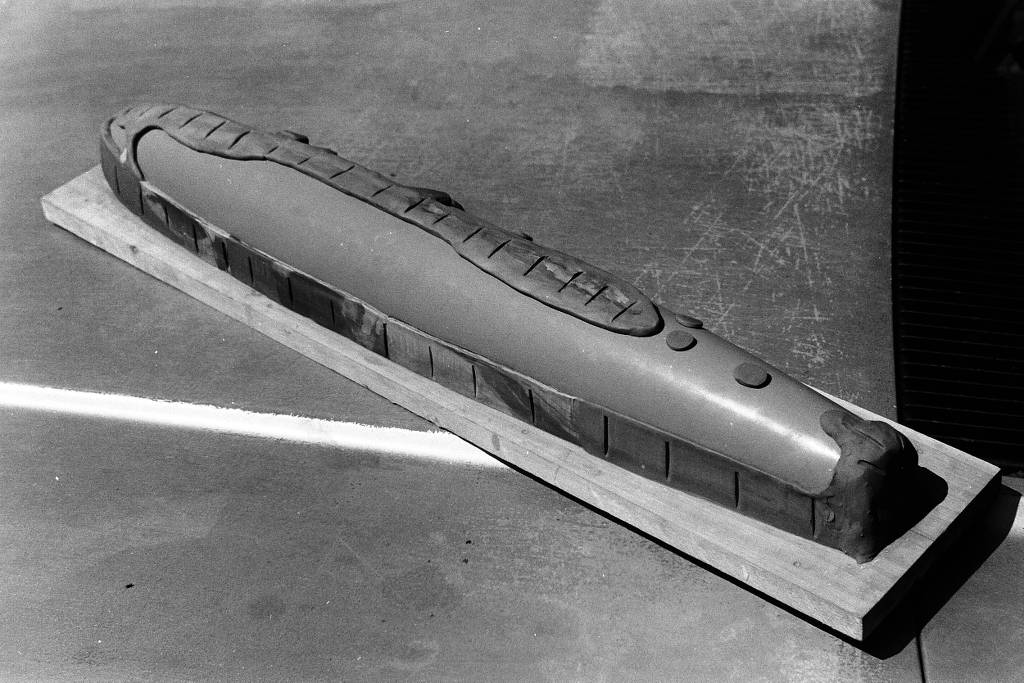
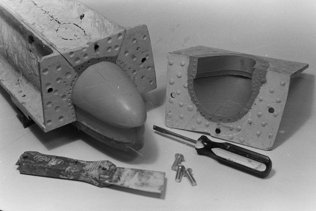
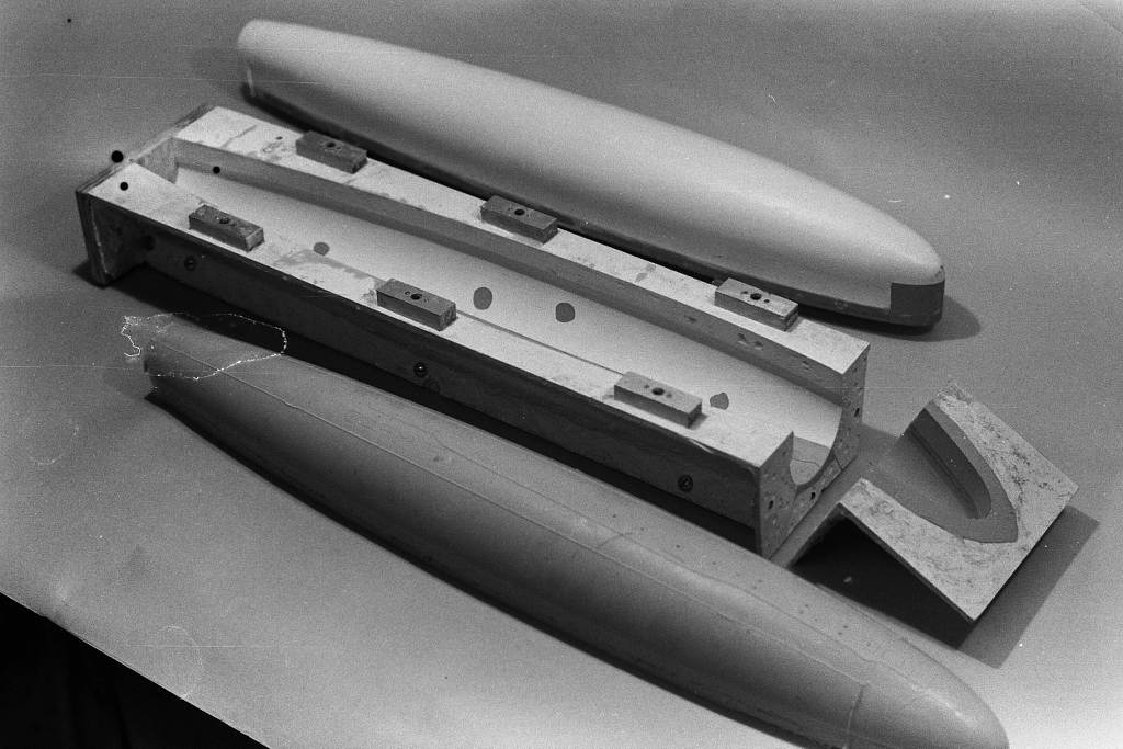
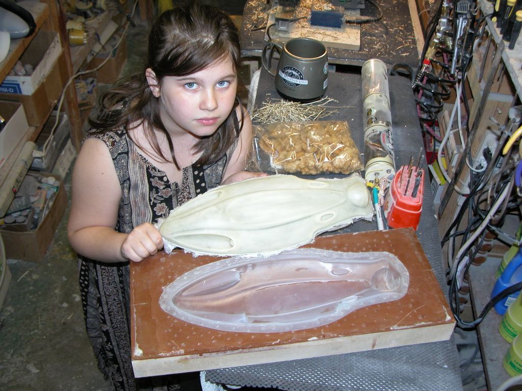
Oh, wait a minute... just found these shots that make me a liar: Ellie and I did a job for MIT in the early 2000's that made use of quick and dirty hard-shell tools:
Ever since then all tools designed for GRP part production have been of the glove-mother mold type, with variations on the theme. My first one was a hybrid that was a traditional hard-shell with rubber inserts that captured all the high draft and engraved details. A tool that embodies the virtues of both hard-shell and rubber contact surfaces.
In addition to the use of rubber elements in the tool to capture detail that a hard-shell element can't, I also developed the 'displacing plug' version. This addition to the tool insured a uniform inside form to the GRP part as well as affording the opportunity to incorporate detail and structures you might want on the model hulls interior.
In my current version (the more traditional form of the tool) the rubber element (the 'glove') is removable from the hard-shell resin (the 'mother'). That is vital as away from the mother-mold, the rubber can be peeled back -- like a glove... duh! -- away from the GRP part which it gave form.
After popping the tail-cone GRP halves out of the tools I set them aside and readied the tools for lay-up of 10-ounce fiberglass cloth to form the first full hull. This hull to proof the tools before I sent them off to the production site, and they would also provide me a personal play-toy down the road.
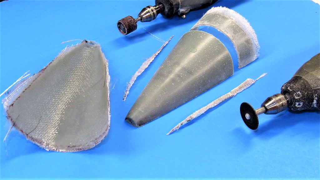
The eventual tail-cone master started life as these two GRP halves, here being trimmed so they can be assembled and then worked into a useful 1/96 STURGEON tail-cone master. More on that horror show later.
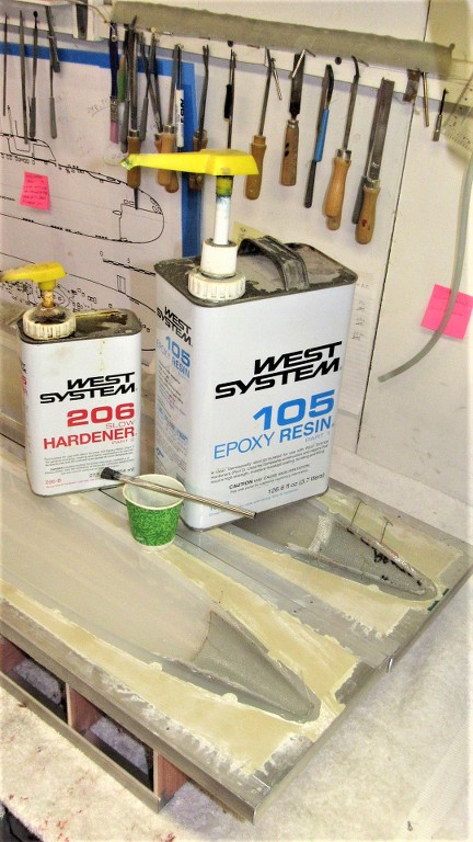
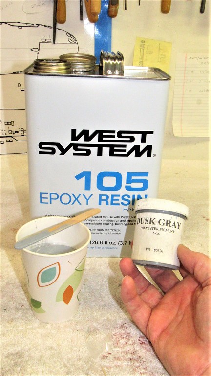
A side note. The West System laminating resin I use produces a semi-clear finish. I prefer an opaque gray -- easier to see flaws in the work. So, I dope the resin side of this two-part epoxy system with a gray pigment. It don't take much!
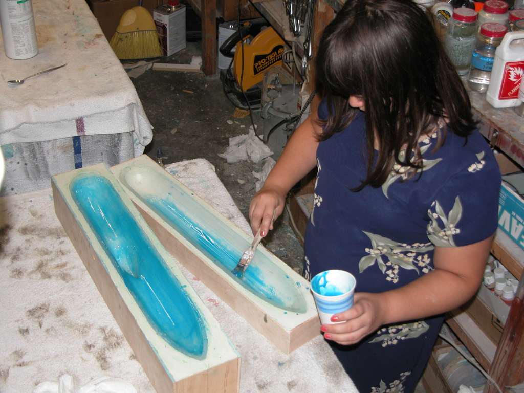
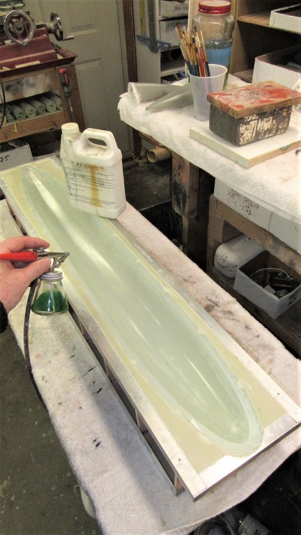
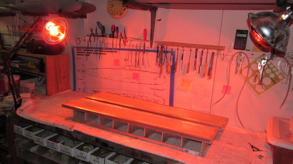
The two hull halves would be laid up in four laminates. The first is a 'gel-coat', a thickened laminating resin used to fill any tight corners (such as the three projecting transducer fairings atop the upper hull) and serve as a leveling buffer between the weave pattern of the glass cloth and the surface of the model parts. Following the gel-coat on went, in quick succession, three laminates of 10-ounce glass cloth.
Nice thing about using RTV silicon rubber as the contact surface between tool and GRP part is the simplicity of the part-release system. Simply a heavy (multiple) coating of polyvinyl alcohol (PVA). This barrier prevents chemical degradation of the rubber through contact with the epoxy laminating resin chemistry. The water soluble PVA is easy to mix, apply, and clean-up. I typically put down five coats with the air-brush, hitting the work with a heat gun between coats to quicken the process.
Gel-coat is home made by mixing up some laminating resin neat, then doping it with something like micro-balloon, talc, mill powder, or colloidal silica (my favorite) to thicken the mess. This produces a high fill, non sagging coating within the tools cavity.
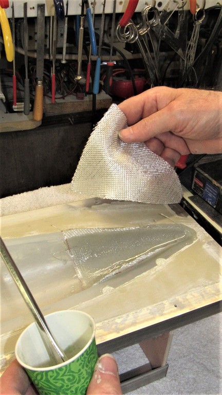
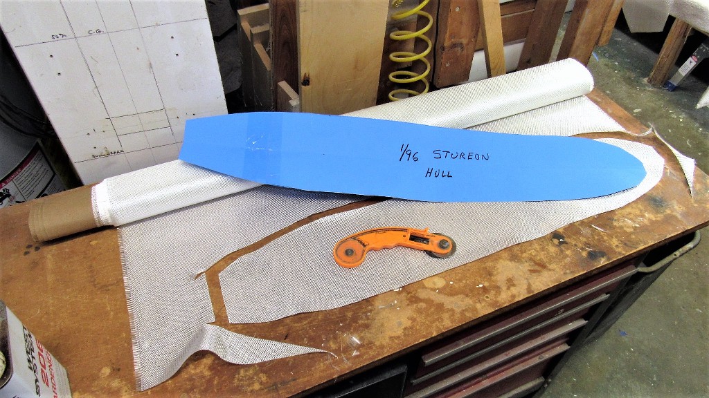
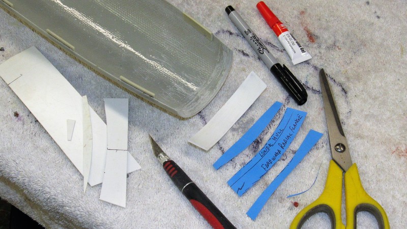
I had prepared a template to guide my pizza-cutter as I cut out the pieces of 10-ounce fiberglass cloth needed for the two hull tools. Gel-coat and three plies of cloth would be enough to get me the 3/32" wall thickness I want on these size submarine hulls.
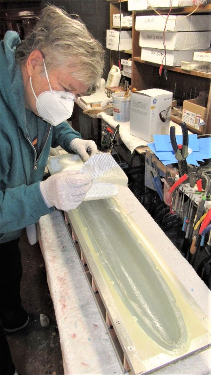
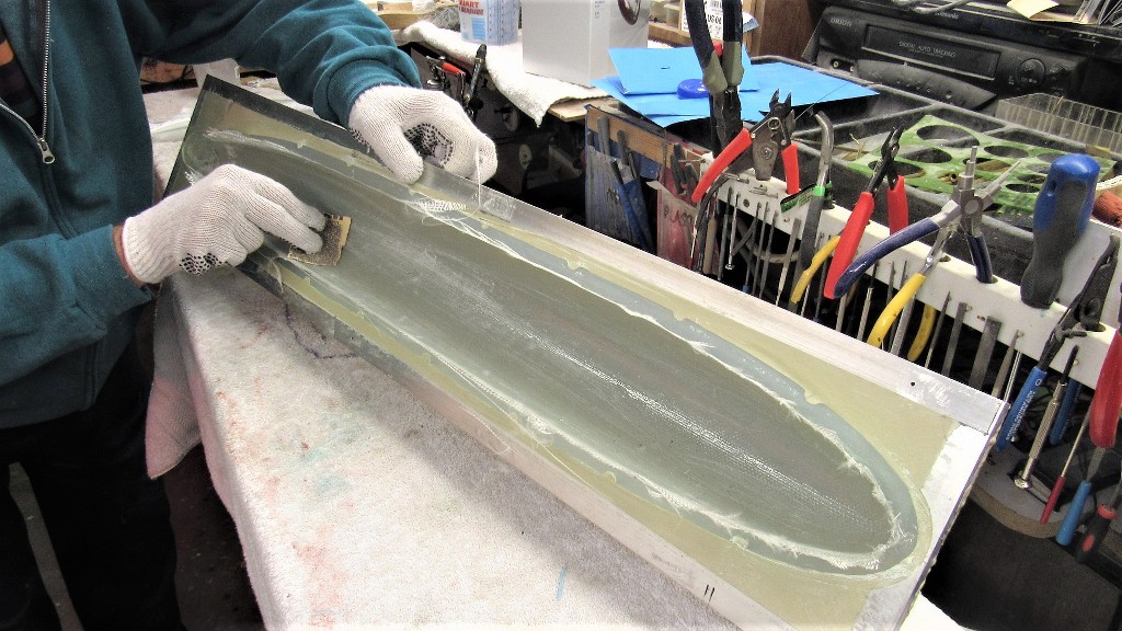
Once the gel-coat hardened I laid in the first laminate of glass cloth and saturated that with catalyzed epoxy laminating resin. I took care to wick out excess resin before it gelled -- the thicker the hull, the more water it displaces, the more ballast tank you need to compensate for that extra buoyancy when the above waterline structure submerges.
After one laminate cures I sand it to knock down any clumps that would prevent proper wetting out of the next laminate.
Meanwhile work continued finishing up the rubber tools so I could cast copies of the stern planes, horizontal-vertical stabilizers, and rudders.
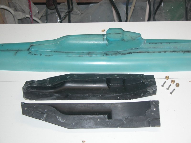
I laid up an upper and lower after section of hull -- that would become a master for the tail-cone which in turn would be used to make a rubber tool for resin casting -- from the completed hull tools. These were bonded together and brought to a perfect round of uniform wall thickness with the aid of two screeding blades.
The two GRP partial hull pieces ready for trimming.
Best way to cut cured GRP is with a carbide cut-off wheel. Safety glasses, respiratory gear, and gloves a necessity here. The trimming out of the way the two halves were tack glued together with CA and glass tape placed on the inside seams and saturated with the epoxy laminating resin. When cured two 3/32" i.d. Oilite bearing were installed in the stern and potted in place with more epoxy laminating resin -- this representing the eventual stern tube that would accept production tail-cone propeller shafts. On this master the centered bearings became the axial reference line about which the screeding blades would swing.
When cured two 3/32" i.d. Oilite bearing were installed in the stern and potted in place with more epoxy laminating resin -- this representing the eventual stern tube that would accept production tail-cone propeller shafts. On this master the centered bearings became the axial reference line about which the screeding blades would swing.
The two screeding blades, how they were made and used:
The gross build up of the tail-cone master wall was done with cheap-ass Bondo. The fine tuning was done with air-dry touch-up putty. This work went very quickly as I employed a heat-lamp to accelerate the cure of the filler, and drying of the putty.
Meanwhile I cast the appendages needed to deck out the tail-cone master.
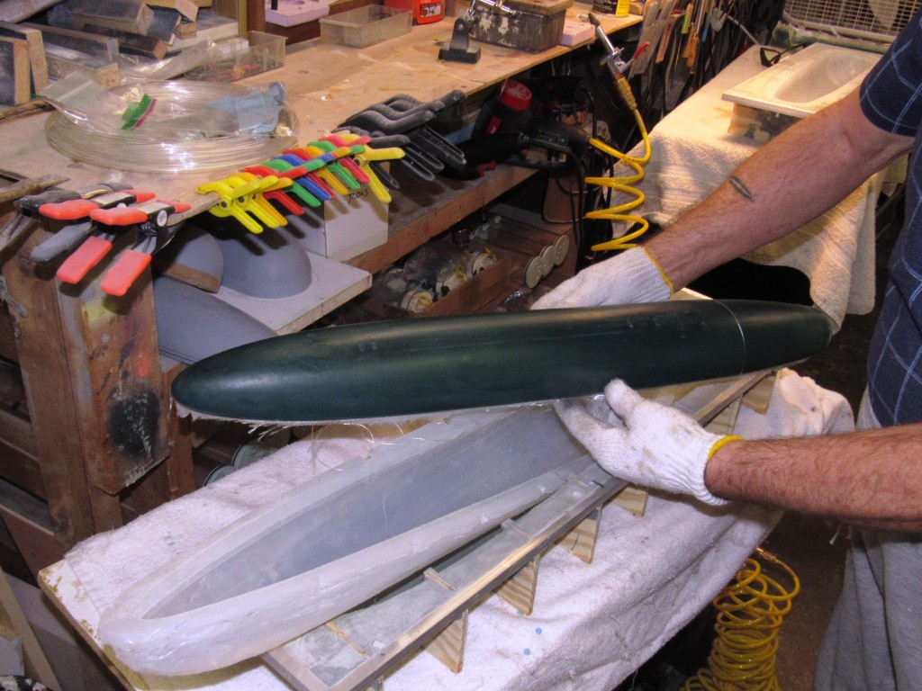
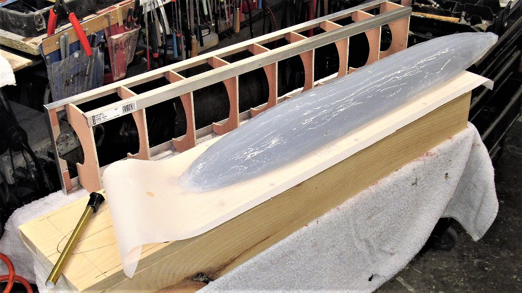
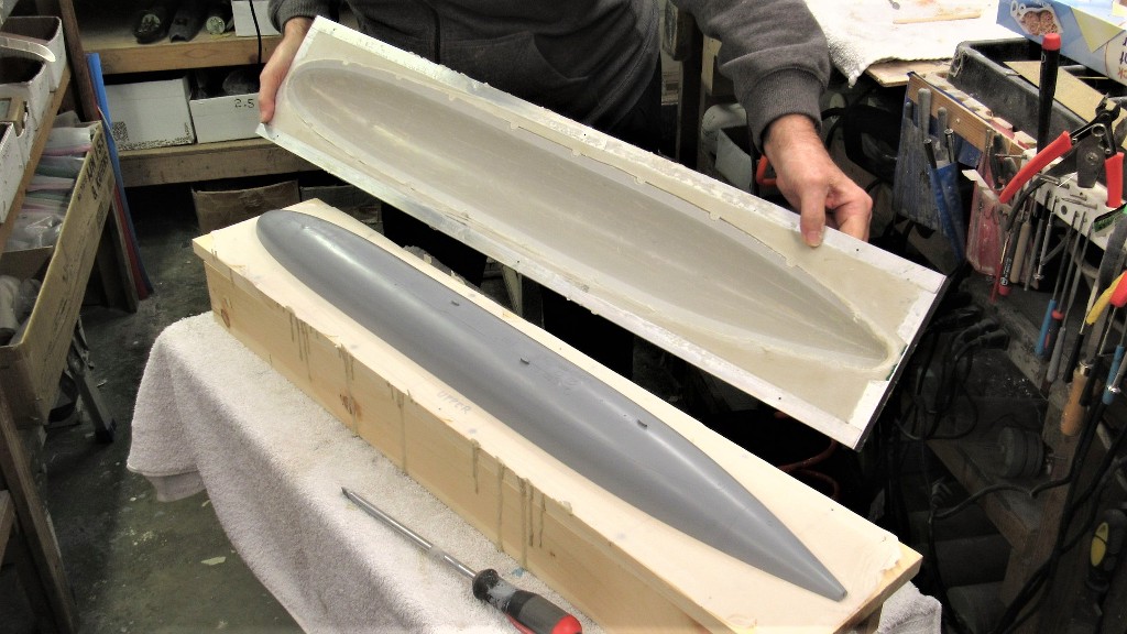
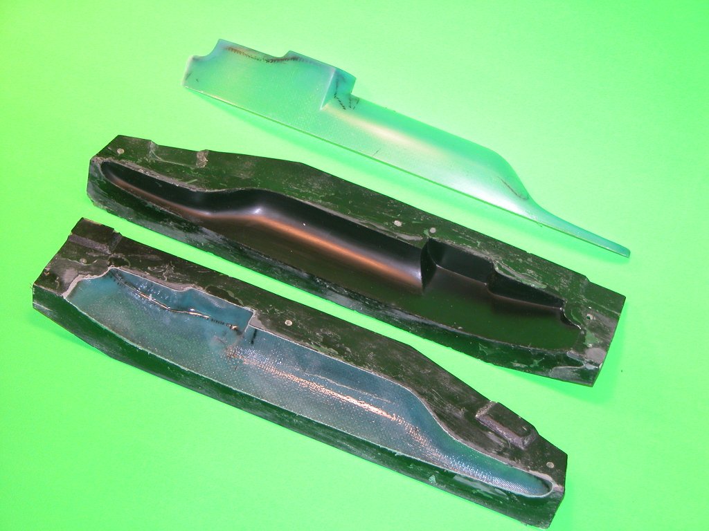
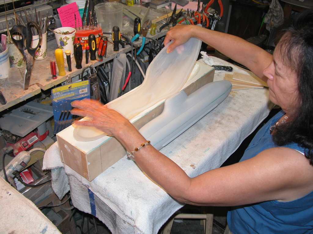
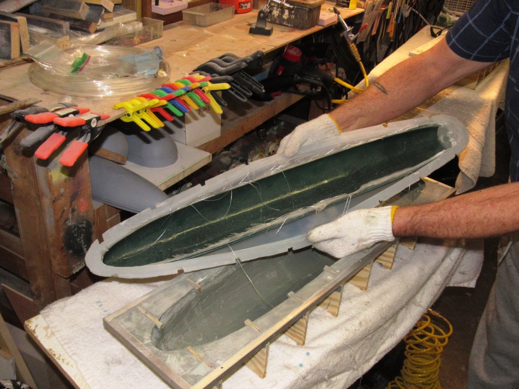
I gave the two laid-up GRP hull parts three days to cure hard in their tools, then popped them out. Though eventually I'll use these hull halves to make my own 1/96 STURGEON r/c model submarine play-toy, their function here is to affirm a good fit to the separate tail-cone master I'm working up -- that tail-cone master eventually used to make a rubber tool from which cast resin tail-cone parts would be produced.
Grabbing some of the above-flange glass fibers I yanked and pulled the laid-up fiberglass hull half clear of the mother-mold, the part still clinging to the glove-mold that gave it shape.
Clear of the mother-mold I'm demonstrating the utility of the glove-mold: I'm peeling it away (glove-like, duh!) from the GRP part. Deep draft, even undercuts, are easily side-stepped during part extraction owing the the flexibility of the glove-mold -- can't do this with a hard-shell type tool!
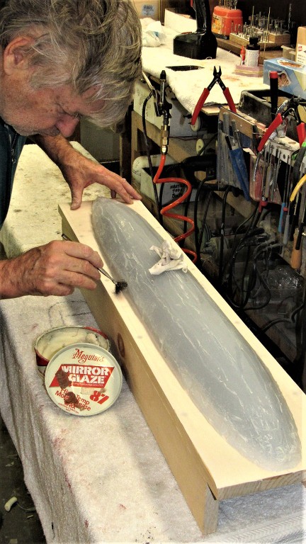
The previously applied part-release coat of PVA still clinging to the GRP parts was easily removed by soaking the hull halves in water which dissolved the PVA, revealing the smooth, highly detailed gel-coat surfaces of the parts. A quick scribing with an abrasive pad soaked in a slurry of cleanser and water, a good rinse, drying, and the parts are ready for adhesives, putties, fillers, and primer.
The ideal tool for cutting GRP -- keep in mind you are cutting GLASS!!! -- is an abrasive cutting tool, typically a sacrificial carbide wheel, diamond wheel, or Tungsten/Carbide/diamond reciprocating blade. I opt for the simple, cheap, and easy to acquire ablative cut-off wheel.
On this rotary tool caddy, in foreground, third from the left, is a very thin blade diamond wheel -- perfect for separating GRP parts when you need to minimize material lost to kerf. To the extreme right are two abrasive cut-off wheels -- good for removing flash and excess glass from the parts flange-line.
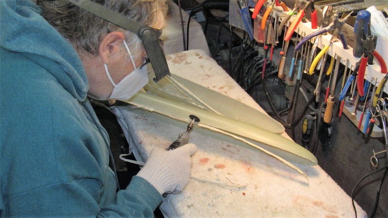
Here I'm get'n medieval on the excess glass. This is an abrasive cut-off wheel, free-handed. The work goes quickly, but raises a cloud of glass fiber and resin particles. This type tool is the way to go as even tool-steel, and your typical 'Japanese saw', or hobby razor-saw will be dulled to uselessness in only a few strokes if you use them on GLASS!
Note the precautions I'm taking to protect my lungs, eyes, and pinkies. Glass is glass and it will bite your ass if you don't take care!
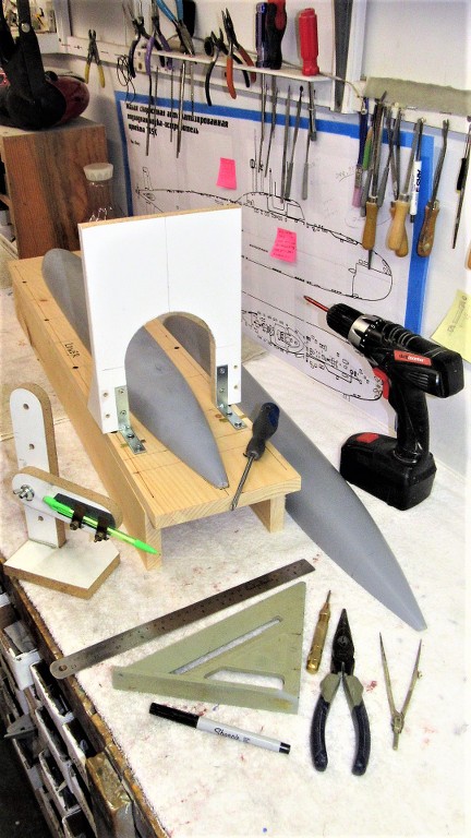
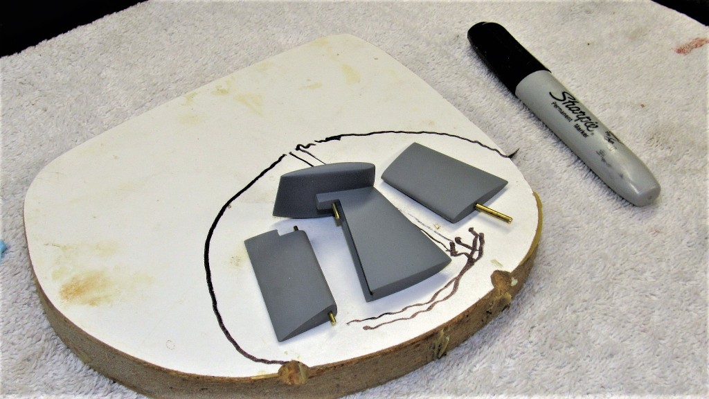
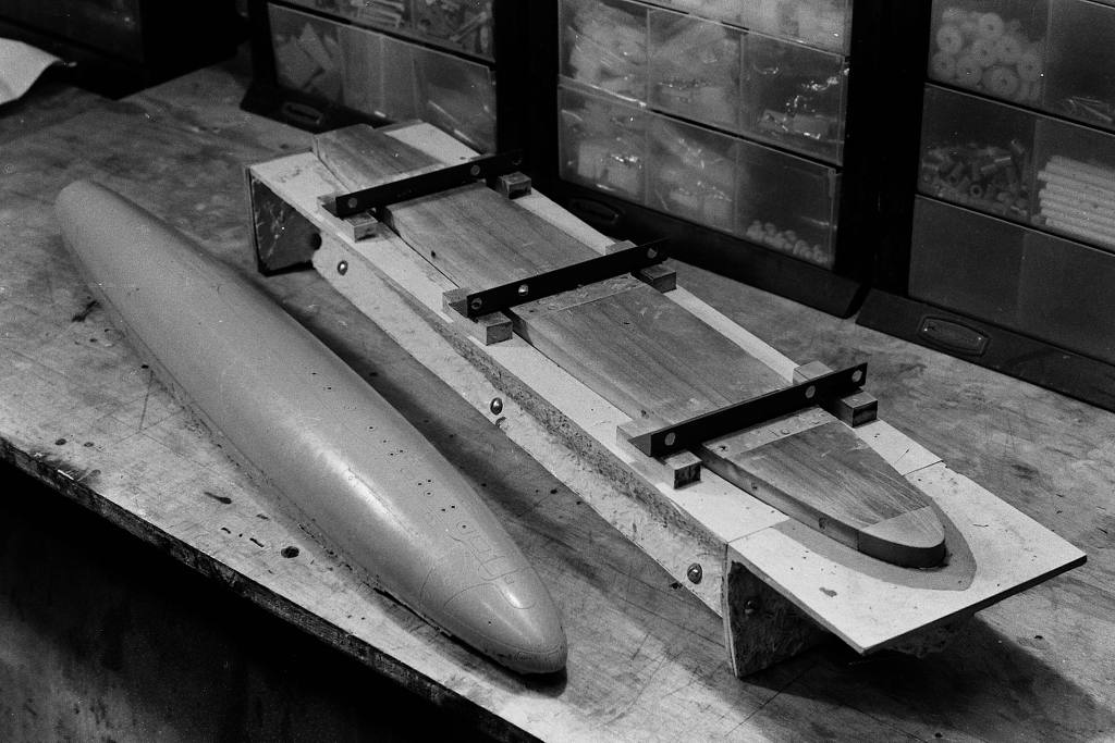
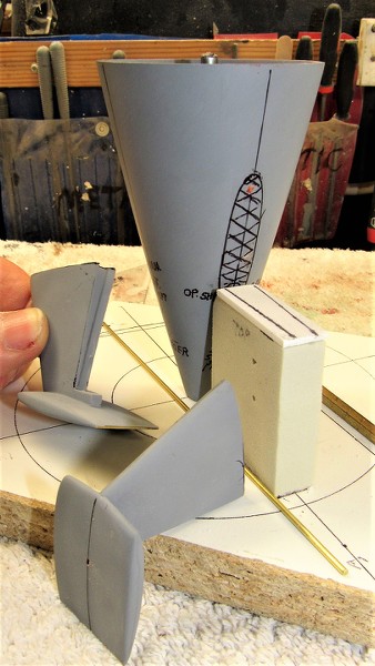
I developed a marking/assembly jig to assist me as I lay-out, mark, and attach the two stabilizer assemblies and drill the operating shaft holes for the two rudders. Symmetry is our friend!
The GRP tail-cone master -- now built up to a robust wall thickness with filler and putty, marked off as to stabilizer and rudder bore locations is test-fit to the stern of the temporarily assembled GRP hull halves to assure proper fit of the eventual tail-cone production pieces.
(As things do shrink a bit during the tool and part castings operations, I oversize the tail-cone master a bit to compensate for that unavoidable deformation).
Once the edges of the two GRP hull halves had been worked smooth, and the sterns -- where a tail-cone part would eventually reside -- had been chopped off and trued to the radial outline, It came time to dissolve off the protective PVA part-release the two GRP hull halves picked up during the lay-up process. This done with the most powerful solvent on this planet: fresh water!
Killing two birds with one stone I mixed up a slurry of water and abrasive laden 'cleanser' powder. This would, when rubbing down the GRP parts with an abrasive pad, not only insure that all the PVA was removed from the parts, it would also produce on the gel-coat surface microscopic abrasions that would produce the tooth needed to insure proper adhesion of glues, fillers, putties, and primer.
Final step here was to scrub the parts with fresh water to remove all soap, set the work aside to air-dry. and move on to other operations awaiting me in the shop.
The tail-cone master marking/assembly jig was used to permanently mount the horizontal-vertical stabilizer assemblies to the tail-cone blank I had formed previous to the hull lay-up work. The jig insures a near perfect symmetry of the two stabilizers to the tail-cone; providing a positive means of suspending a stabilizer assembly against the side of the tail-cone as CA was applied to tack the pieces together.
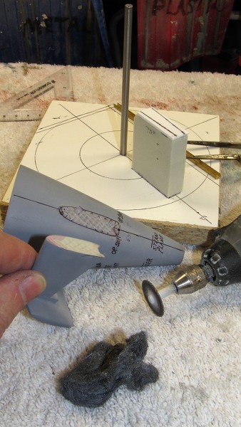
A RenShape 'crutch' atop the surface of the jig held a stabilizer assembly at the correct angle and height. In order to outline the area of the tail-cone the root of a stabilizer assembly would cover I hand-held a stabilizer and inked its outline onto the tail-cone.
The root contact area of tail-cone and stabilizer assembly were roughed up with a cut-off wheel to increase the glue contact area during final assembly.
The jig insures repeatability and accuracy of assembly between parts, and is the only way I know of that will insure symmetry of spacing between like items, as well as correct orientation to one another about all planes of reference. This kind of work is not done by eye-ball alone. Often fixture and jig design and construction are more involved and take longer than the model parts themselves! Methodology, understanding of material physical and chemical properties, and a well structured chronology of events are key elements to successful model-building.
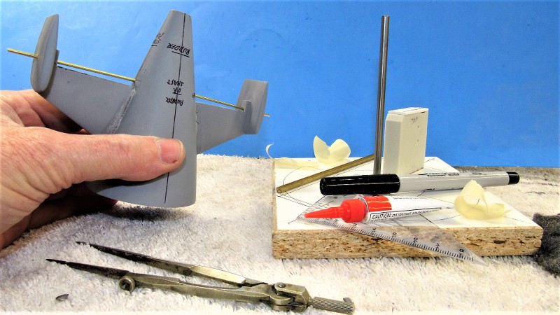
The stabilizer assemblies now tack glued to the tail-cone, the master was pulled away from the jig and CA added to the joints, letting capillary action to its work of wicking the glue into the gaps. Sprinkling on baking soda produced a hard grout that quickly cured. Riffler files and spot applications of CA-baking soda, followed by more careful filing, made tight the seams between stabilizers and tail-cone.
Before assembly I had drilled holes where the operating shafts of the stern planes would pass into the tail-cone. Here I'm checking for unbinding fit of a 1/16" diameter brass operating shaft stand-in to affirm I will have free operation of the stern planes. The bearing points for the operating shafts are at the vertical stabilizers outboard, and the tail-cone inboard.
And a test-fit of the stern plane masters to check fit and clearance of the planes to the stabilizers and tail-cone.
Continuing to turn the initial work on this kit into a practical 'demonstrator' I went about the task of producing the 'Z-cut' employed by many r/c submarine drivers to access the interior of their model to get at the inner workings. Typically the Z-cut is made by attaching a bow portion from the lower hull to the upper hull, and attaching the upper hull stern piece to the lower hull. The eventual cast resin tail-cone assembly will take care of the stern. Here, I'm attaching the lower hull bow piece to the upper hull.
I used the radial sonar dome engraved line as the demarcation line were I would separate the lower hull bow. A low-kerf cut-off wheel did the job well and I prepared the upper hull for attachment by gathering the adhesives, reinforcing glass tape, and tools needed to perform the transplant surgery. At this stage I roughed up the insides of the bow pieces and hull to insure good adhesion of the reinforcing glass tape.
The lower bow was tack-glued to the upper hull with CA, then ten-ounce glass cloth strips were laminated across the seam on the inside of the hull. Nothing to it! The same West System epoxy laminating resin used for glass lay-up was used to saturate and bond the glass tape to the inside of the hull.
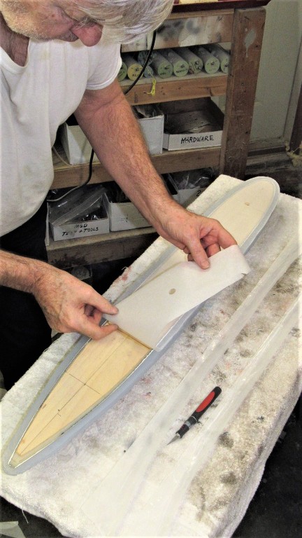
The marvel of the Z-cut is that only one, small mechanical fastener, aft, is all that is needed to secure the assembled hull halves together. But, a capture lip -- a radial flange -- within the forward edge of the lower hull has to be provided. This radial flange was first mocked up in cardboard, and once happy with it, the template was used to mark out a piece of .060" thick styrene sheet.
Nice thing about most thermoplastics is that they can be work-weakened to assume an awesome simple curve if needed. I did this with the radial flange piece by pinching it between a dowel and thumb as I pull it along at an angle. The curved flange was set in place within the lower hull. About 1/4" of it projecting forward past the end of the hull. It was CA'ed in place.
To insure that the removable hull halves would key together tightly I installed resin ' indexing tabs' within each hull, slightly raised above the longitudinal edges so that the assembled hull would fit with the longitudinal edges in near perfect alignment. These cast resin items attached within the hull halves with CA adhesive.
Fortunately, both the THRESHER and STURGEON class submarine had the same diameter and pretty close hull form. So, I dug out the tooling I had prepared for a THRESHER kit I authored a few years back, and pressed those into service to produce the indexing tabs, capture lips, WTC saddles, and Velcro foundation pieces needed for this STURGEON model. Sometimes fortune smiles...
Here's how the staggered indexing tabs interlock to keep the upper and lower hull halves in alignment. We're looking through the opening at the stern, where the eventual tail-cone assembly will be bonded to the lower hull.
Supplementing the radial flange and indexing tabs at the bow were two carbon fiber reinforced capture lips. These interlock with the indexing tabs to pull the upper hull up tight against the radial flange of the lower hull.
I'm pushing to complete the tail-cone master so I can make its tool and get on with production of cast resin parts.
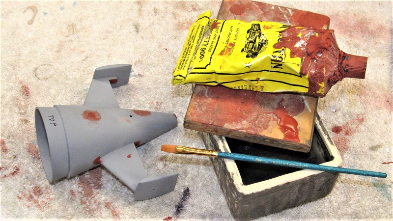
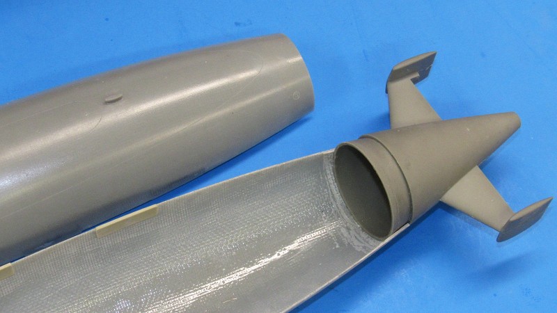
With this picture I jump ahead to show the finished product. Note the fidelity of the seam work between stabilizers and tail-cone; also note the uniform gap between stabilizer trailing edge and stern plane leading edge. The following work outlines how such magnificence was achieved. Gap filling was done in two stages: building up CA-baking soda grout to fill the gross gaps and filing that back; then filling the tool marks with air-dry Nitro Stan air-dry automotive lacquer putty, followed by careful wet-sanding.
The ideal tool for cutting in right angle joints and joints of negative draft is a three-face bastard cut file. It cuts quickly and if held correctly will not damage the adjoining work. The file must be cleaned periodically with a wire brush (file card) designed for the task. This work is done dry and the teeth will clog with only a few strokes. You can't clean a file too often! Any seam gaps revealed during this work were filled with CA and grout, and cut back with the file.
A flat second-cut file was used to remove most of the tool marks. I then applied air-dry putty to address the scratches. After that had dried, the seams were wet sanded with stiff sandpaper, starting with #220 and working up to #400. This work was done wet to keep the abrasive particles from clogging the abrasive.
Unfortunately the stern plane leading edges did not describe a half-cylinder section at the leading edge. This had to be built up with Bondo filler and then worked with file until the proper shape had been achieved.
(Like a dumb-ass I failed to find this fault with the original master -- had I done so, I would have had to make only one fix, not two as was the case here -- Piss Poor Planning Produces Pucked Product!).
The gap between the assembled stern planes and horizontal stabilizers was too tight. I slipped a length of #200 sandpaper into the gap -- grit side against the stabilizer concave trailing edge -- and cycled the planes. This quickly, and uniformly, widened the gaps between stern planes and stabilizers. Finishing strokes were done with a layer of #400 sandpaper to smooth out the trench created.
I needed to get away from that frig'n tail-cone job. So, I slapped together a yoke for the stern planes. This item makes up the inboard ends of the stern plane operating shafts so they can work uniformly. The yoke permits passage of the centrally running propeller shaft. Soldering 101. Wheel collars are my friend!
OK, back to this pain-in-the-ass tail-cone master: At the forward end of tail-cone is a radial flange that mates with the inside stern of the two hull halves when they are assembled. The tail-cone part (on an assembled model kit) is glued to the lower hull. The upper hull, when assembled, sits atop the tail-cone radial flange. A single mechanical fastener running through upper hull and radial flange secures the two hull halves together. Slick!
The radial flange was turned from a hunk of 40 pound-per-cubic-foot RenShape model-builders board. It was then CA'ed to the forward end of the tail cone.
There!! A little scribing work, a finish sanding, and I can get started in on the tool for this thing.
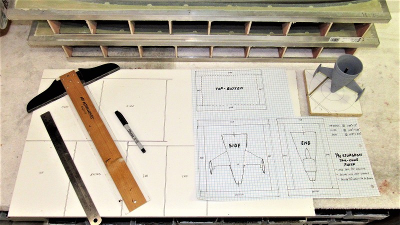
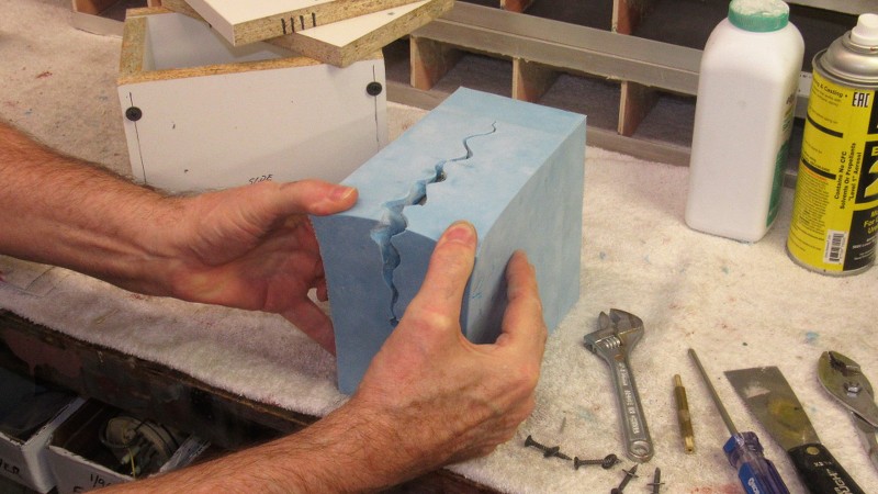
With the 1/96 STURGEON tail-cone master nearing completion it came time to address how the three-piece rubber tool would be cast.
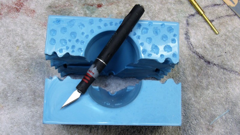
Here I'm showing the end-game of tail-cone tool making, using this 1/96 BLUEBACK tool as a fair representation of what the STURGEON tail-cone tool will look like.
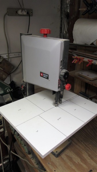
A flask -- a box-like containment that holds the liquid mold making RTV rubber in place as it changes state to a solid -- is constructed from 5/8" thick particle board 'shelving'. Later, during cast resin part production, this flask serves to hold the tool ridged and the three parts that constitute the tool held in perfect registration with one another
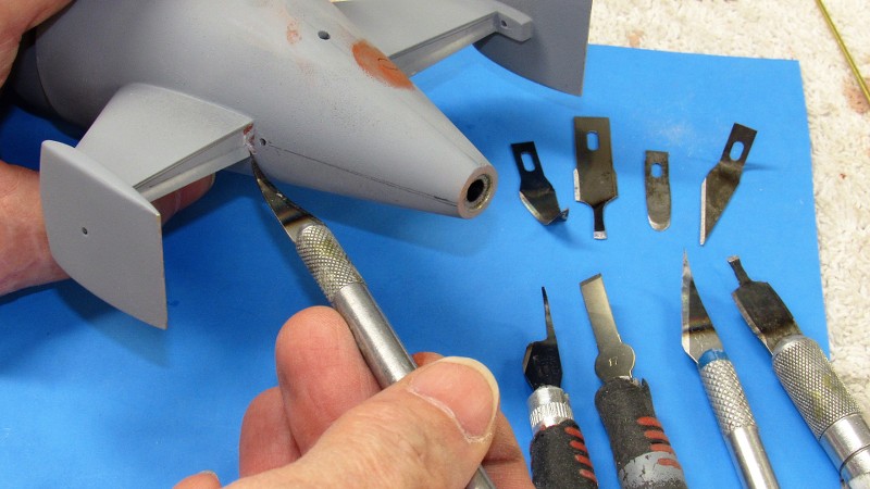
Some hard-to-get-at spots on the tail-con master -- such as the horizontal stabilizer trailing edge concave, where that trench joined the tail-cone and vertical stabilizer -- were best fine-tuned with special knifes made just for these type tasks.
These special knife blades were ground to the desired shape and sharpened, then bent after taking the blade to a red heat. Each started life as a common X-Acto knife blade, but altered to my specific need.
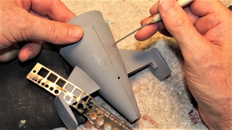
From the plan I lofted the engravings onto the master in pencil. Once happy with the lay-out I committed to the engraving tool
Scribing on the tail-cone master was a real chore. As I was engraving into four types of substrate -- GRP, Bondo, air-dry putty, and primer -- I had to take extreme care with the strokes of the scratch-awl as I cut into the surfaces, the engraving tool guided by stainless steel stencils.
The hard to avoid boo-boo's with the scribing tool were addressed with air-dry putty and the problem areas again addressed with the scratch-awl. Once the scribe work was cleaned up I pencil marked all spots on that master requiring touch-up putty.
Air-dry putty was applied with a brush. To keep the quick-dry putty of a desired consistency I occasionally dipped the brush in some lacquer thinner and mixed up some putty till it was again brushable. Once the spot-putty had dried, those areas were wet-sanded, the master given a last coat of primer, and given a final dry-sanding with #400 sandpaper.
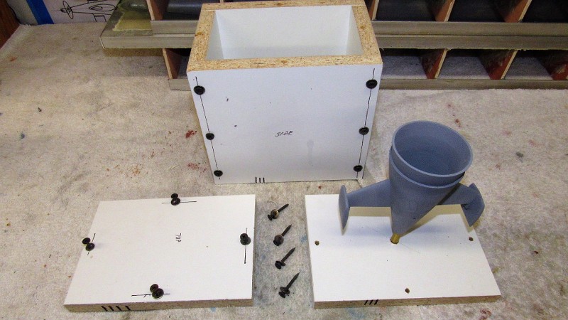
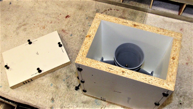
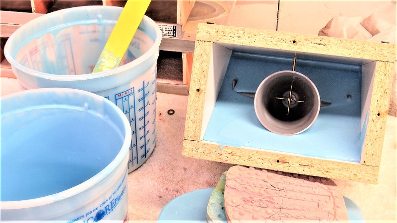
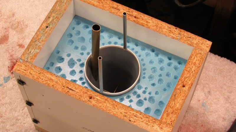
The completed tail-cone master was secured to the bottom of the containment flask with a 5/16" pin. This pin is the same diameter of the eventual Oilite bushings that will fit within the cast resin tail-cone piece. That bearing in turn accepting the propeller shaft. The pin you see here not only suspends the master within the flask so it can be properly encapsulated in rubber, it also produces the bore that will accept, during resin part pouring, another pin that will produce the Oilite bearing bore.
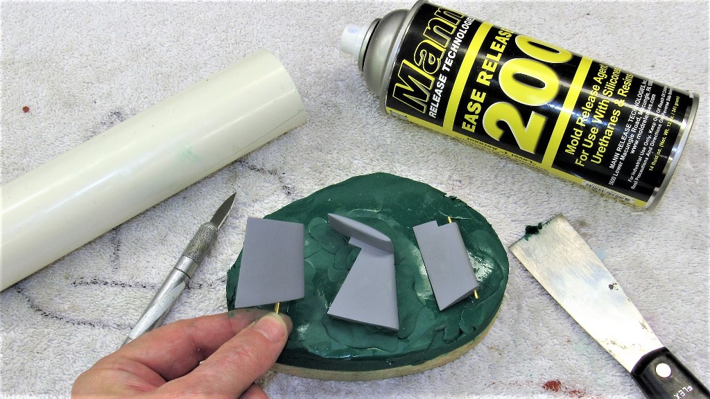
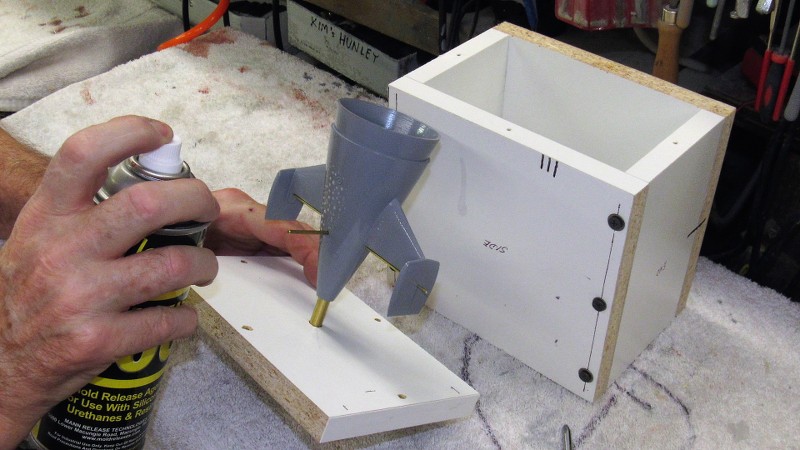
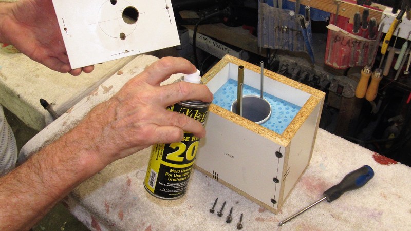
Here I'm applying Mann 200 spray-on mold-release silicon just before placing the master in the flask.
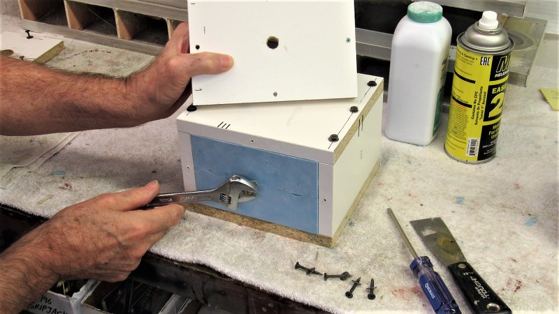
All six pieces of the flask have been indexed to insure it all goes together the same way. The pieces are secured with deck-screws -- this permits me to take the flask apart when it comes time to access the rubber tool for master extraction and later resin casting preparation and part removal.
Note the brass rods projecting from the sides of the tail-cone. These form bores within the tool that will accept rods that will create bores in the cast resin tail-cone parts to accept the rudder and stern plane operating shafts.
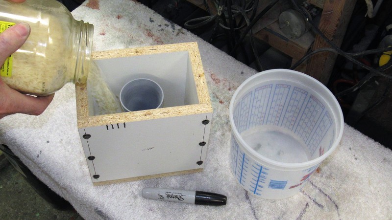
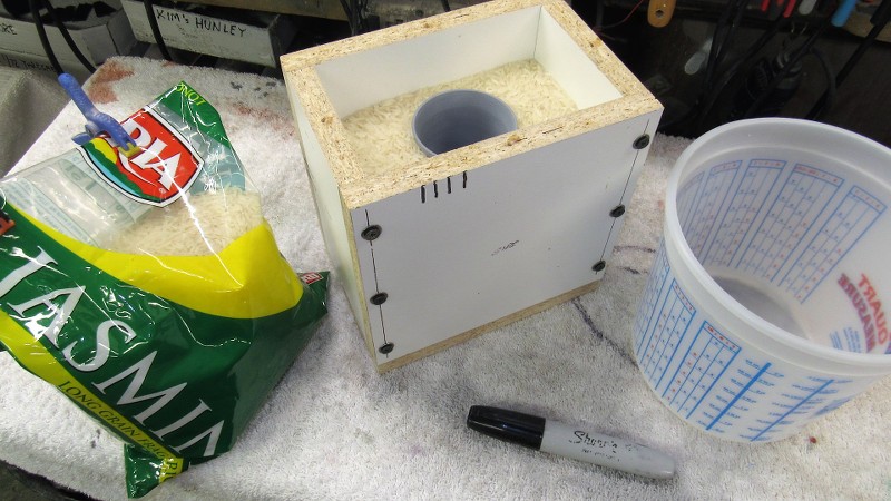
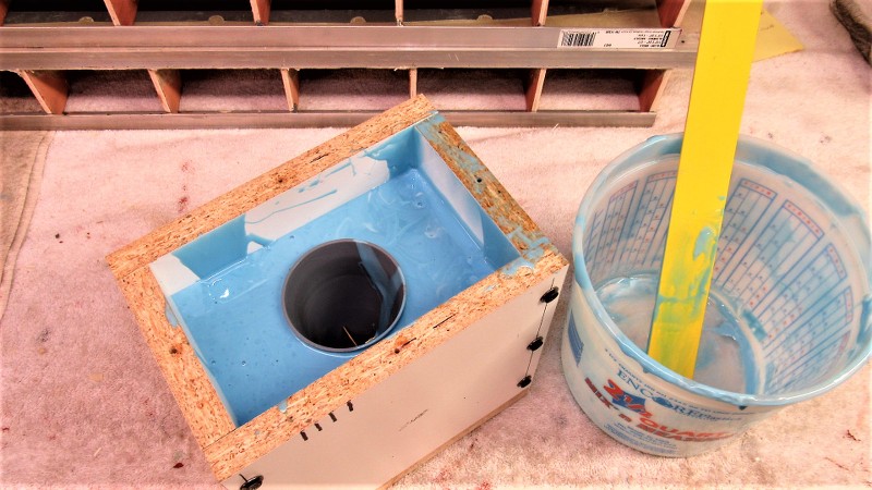
I determine the amount of RTV rubber needed for a job by going the 'rice' route: You simply pour rice into the void between master and flask containment till you reach the top or the point where you want the second pour of tool making rubber to start. In this case I want the initial pour of rubber to top off at the mid-point of the masters radial flange.
Math?... we need no stink'n math!
One of the many advantages of hooking up with an Asian gal is that there is always plenty of rice in the house! (Sheeee... she must never know).
It's then a simple matter to pour the rice into the rubber mixing container and mark off the container -- that mark indicates exactly how much tool making rubber you need to mix up. Duh!
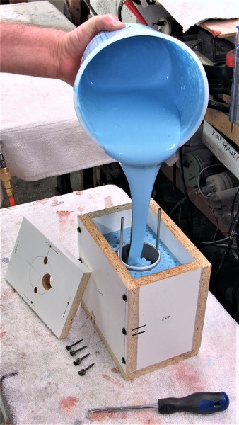
I started the tool making rubber pour by severely angling the flask like this to insure that no air-bubbles would be trapped under the concave troughs of the horizontal stabilizer trailing edges. Once those areas were submerged in rubber I positioned the flask upright and finished the pour.
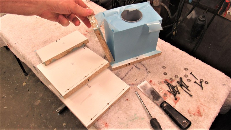
After about twelve-hours under two heat-lamps the block of Silicon Room Temperature Vulcanizing (RTV) rubber had cured hard and I took the flask apart.
I yanked out the brass rods and established centerline verticals on the rubber block to help guide me as I cut the block into two approximately equal halves -- that operation, inevitably sloppy, would produce the keying network that would register the two halves together. More on that horror show shortly.
I purposefully avoided straight cuts at the surface of the block of rubber -- the wavy lines would insure an aggressive keying network. But, about a half-inch into the cut I straightened the flange as best I could and worked as carefully as I could to avoid cutting into the master, though some dings (easily filled and sanded smooth later) did occur.
Into the top of the block, that world become the flange line of the core piece of the tool, I dug out deep 'dimples' to start the keying network between the core portion of the tool and the two-piece block of rubber beneath.
The tail-cone master was reinstalled into the two piece 'block' and a riser ring attached to the forward end of its radial flange -- a form of bubble-catcher. Atop the riser are two tubes that will form the vents within the core portion of the too.
Pouring the third section of the tool. The large brass pipe will form the sprue.
I do a fair amount (well, before 2020 I did, anyway) of 3D CAD modeling, followed by 3D printing. It's hard to imagine a more theoretically precise way to make a part than a freakin' replicator. And yet, AND YET, nothing ever comes out looking as good as the keister of that there submoboat.
Why? Frakkin' *craftsmanship.* CAD/3D printing is a hell of a tool, but tools are useful means to an end, not the end themselves. Especially when you then have to go and make copies...
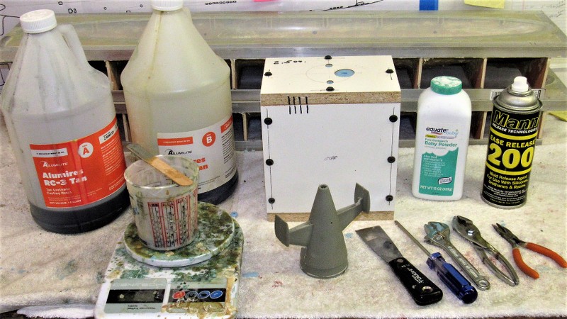
And FINALLY! I transition from tool making to part making. Here is the typical set-up for the casting of a polyurethane resin part. The resin, mixing container, scale to measure the liquid resin, the assembled tool, the hand-tools used to install/remove the core pins, and the talc and part-release silicon spray used to protect the rubber from chemical attack from the resin as it changes state from liquid to solid.
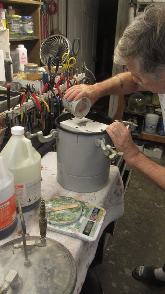
Introducing catalyzed resin into the tools cavity through the large diameter sprue hole. Before the resin begins its state change the entire tool is subjected to pressure to crush any small bubbles of gas entrapped within the tools cavity -- this to insure a pock-mark free casting. The pressure pot is of the kind used in pressure spray-gun equipment, an item available at any local Harbor Freight.
The Alumilite resin I use can be demolded within twenty-minutes after the pour, but I typically let things set for a good hour before un-pressurizing the pot, removing the tool, and stripping out the cast resin part.
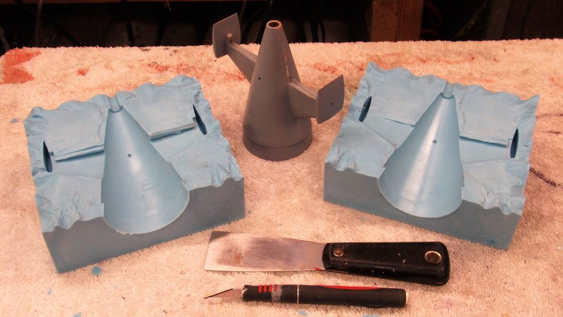
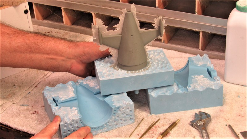
Removal of the rubber elements of the tool from the flask starts with twisting the base-pin from the bottom -- this pin serves as a core element that forms the 5/16" bore at the stern of the tail-cone casting that later accepts the Oilite propeller shaft bearings. I milled two flats to the lower end of the pin to permit easy twisting with a wrench, breaking it free from the hardened resin. It was then an easy task to pull the pin clear.
Removing the brass rods that gave for to the holes in the sides and outboard tips of the horizontal stabilizers of the tail-cone piece. Those holes later passing the operating shafts of the stern planes and rudders.
Seen to good advantage here the zig-zag keying between the two halves of the 'block' that comprises the majority of the tail-cone rubber tool.
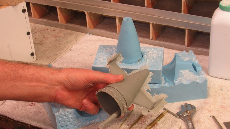
The four pins removed from the block, the two halves are pulled apart revealing the cast resin tail-cone part still attached to the core portion of the rubber tool that produces the parts hollow, thin-walled, interior. A little flexing of the rubber and part and it pops clear of the core. Only clean-up of the part is to shave off some flash, snap off the ring shaped riser, and grind the sprue away from the parts interior.
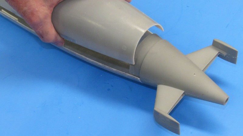
Test fitting the tail-cone part to the GRP hull. Note how the radial flange will be glued to the lower hull, leaving the upper portion of radial flange to serve as the foundation upon which the after end of the upper hull will sit and be secured to with a single machine screw. Easy, quick access to the hulls interior -- the marvel of the Z-cut; an invention promoted many years ago by the two Canadian's, Greg Sharpe and Dan Kachur.
That's a blast from the past! What publication was that. I forgot.
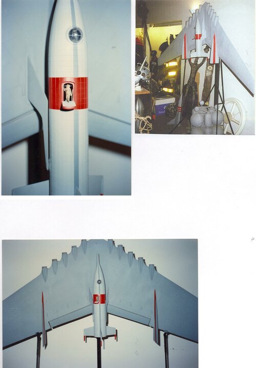
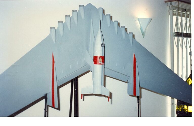
It was, and always will be, an honor to have been involved in that restoration job. Some of the greats were in on that re-build and display: Bob and Dennis Skotak, Mike Minor, Bob Burns, and I think Tom Sherman.
That's a blast from the past! What publication was that. I forgot.
It was, and always will be, an honor to have been involved in that restoration job. Some of the greats were in on that re-build and display: Bob and Dennis Skotak, Mike Minor, Bob Burns, and I think Tom Sherman.
This site uses cookies to help personalise content, tailor your experience and to keep you logged in if you register.
By continuing to use this site, you are consenting to our use of cookies.