
You are using an out of date browser. It may not display this or other websites correctly.
You should upgrade or use an alternative browser.
You should upgrade or use an alternative browser.
Martin-Baker M.B.1,2 and3
- Thread starter Johnbr
- Start date
- Joined
- 19 October 2012
- Messages
- 1,984
- Reaction score
- 1,941
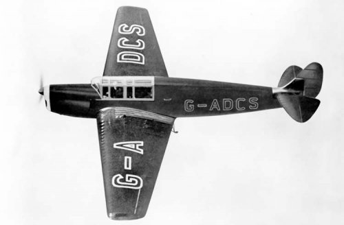
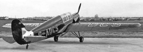
lark said:This is indeed the first unbuilt Martin MB.1 project of the early '30's.
A two seater powered by a DH Gipsy engine behind the seats.
Not quite correct as the aircraft, which may have been designated M.1 (pre Martin-Baker), was built in the Martin's Aircraft Works commencing in 1929 but never completed as funds ran out. The engine is generally said to have been a 120hp Cirrus Hermes.
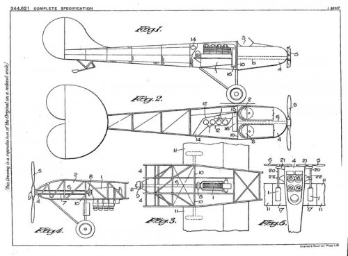
The early form of the design can be seen in this 1929 patent,
Attachments
- Joined
- 19 October 2012
- Messages
- 1,984
- Reaction score
- 1,941
While the MB1 was under construction - a 'proof of concept' design for Martin's tubular-steel construction system- he patented this design for a tandem two-seat aircraft. The engine was in the upper mid fuselage and drove the propeller via an extension shaft that passed above the cockpit. The wings appear to be identical to those of the MB1, which gives an idea of the size. It is smaller than it appears.
Attachments
- Joined
- 19 October 2012
- Messages
- 1,984
- Reaction score
- 1,941
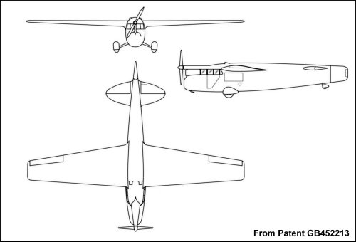
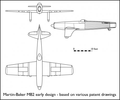
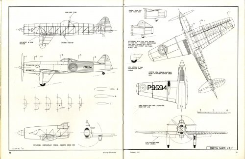
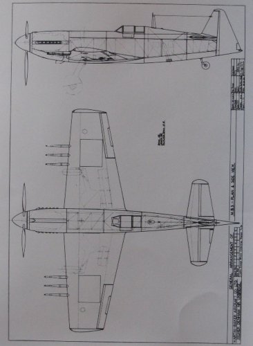
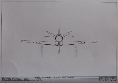
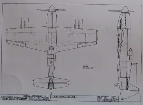
While reviewing the Martin-Baker patents I decided to use the various illustrations to create a 3-view of what the initial MB2 design may have looked like. There are patents covering the exhaust system, roll pillar, fuselage construction, rudder and gun installation, all with illustrations that are clearly of the MB2. However they are not always 100% consistent, as you would expect as the design evolved, with the depth of the fuselage, the position of the cockpit, and shape of the canopy changing slightly, so this is a 'best-guess' based on the earliest versions of drawings. The only part that was never shown was the outer wings, but based on the gun installation drawing they were probably of slightly greater span than on the final aircraft.
Attachments
Johnbr
ACCESS: Top Secret
- Joined
- 6 May 2007
- Messages
- 753
- Reaction score
- 329
blackkite
Don't laugh, don't cry, don't even curse, but.....
- Joined
- 31 May 2007
- Messages
- 8,819
- Reaction score
- 7,718
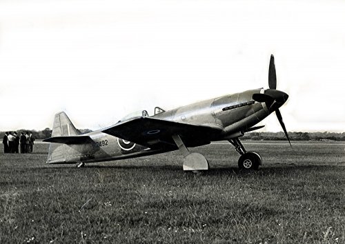
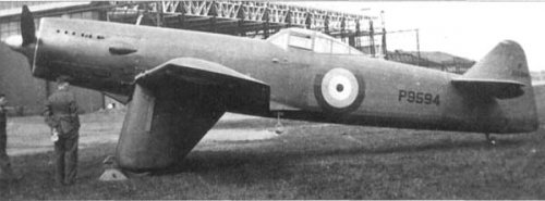
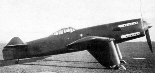
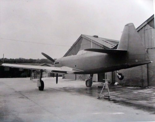
MB2's vertical tail stabilizer area was increased through flight test.
http://www.res-aeronautica.com/martin-baker-mb.2-2.php
I can see engine cooling air outlet position and retractable undercarriage version by this site.
http://p-d-m.livejournal.com/47158.html#/47158.html
Justo-san's excellent contribution.
https://www.secretprojects.co.uk/forum/index.php?action=dlattach;topic=7053.0;attach=74551;image
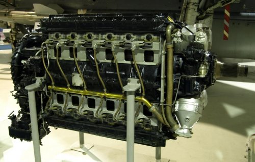
Napier Dagger engine.
https://en.wikipedia.org/wiki/Napier_Dagger
"The Napier Dagger was a 24-cylinder H-pattern (or H-Block) air-cooled engine designed by Frank Halford and built by Napier before World War II. It was a development of the earlier Napier Rapier"
http://www.res-aeronautica.com/martin-baker-mb.2-2.php
I can see engine cooling air outlet position and retractable undercarriage version by this site.
http://p-d-m.livejournal.com/47158.html#/47158.html
Justo-san's excellent contribution.
https://www.secretprojects.co.uk/forum/index.php?action=dlattach;topic=7053.0;attach=74551;image
Napier Dagger engine.
https://en.wikipedia.org/wiki/Napier_Dagger
"The Napier Dagger was a 24-cylinder H-pattern (or H-Block) air-cooled engine designed by Frank Halford and built by Napier before World War II. It was a development of the earlier Napier Rapier"
Attachments
blackkite
Don't laugh, don't cry, don't even curse, but.....
- Joined
- 31 May 2007
- Messages
- 8,819
- Reaction score
- 7,718
MB3 pictures. I can see radiator cooling air outlet at the wing trailing edge.
http://www.modelarovo.cz/letouny-martin-baker-mb-3-mb-5-fotoreport/
MB3 three side view drawing source. Radiator size of left side wing and right side wing are different. Or radiator and oil cooler?
http://www.aviastar.org/air/england/martin-baker_mb-3.php
http://controlline.org.uk/phpBB2/viewtopic.php?printertopic=1&t=10493&postdays=0&postorder=asc&start=0&finish_rel=-10000
MB4 is here.
https://www.secretprojects.co.uk/forum/index.php?topic=7053.0
https://www.youtube.com/watch?v=uUZsmMzwxnw
Attachments
Silencer1
That now I am the Ruler of the Queen's Navee!
- Joined
- 3 August 2009
- Messages
- 897
- Reaction score
- 582
Schneiderman said:While reviewing the Martin-Baker patents I decided to use the various illustrations to create a 3-view of what the initial MB2 design may have looked like.
Dear Schneiderman!
Did you know, what are the reasons of MB-2 designers to use such small rudder and no fin for it's initial configuration?
Looks, that aircraft structure has have many modern features, although lack of vertical empennage looks strange, IMHO.
- Joined
- 19 October 2012
- Messages
- 1,984
- Reaction score
- 1,941
Well, James Martin was a self-taught engineer who rarely listened to the opinions of other people. While he was extremely good at designing elegant engineering solutions for gun installations and other aircraft components, and later with ejection seats, his knowedge of aerodynamics in the mid 1930s was somewhat limited. He thought that the long-narrow rear fuselage would provide adequate stability and a fin just added drag. I'm surprised that Valentine Baker, a very experienced pilot and instructor, was prepared to fly the MB2 in this form. The fin and rudder were modified after the first flight and again a few days later.Silencer1 said:Dear Schneiderman!
Did you know, what are the reasons of MB-2 designers to use such small rudder and no fin for it's initial configuration?
Looks, that aircraft structure has have many modern features, although lack of vertical empennage looks strange, IMHO.
The moral of the story is that smart people are not necessarily smart in everything they do and it is sometimes hard for others to convince them that they are not right all of the time. There are others in the aircraft design business who made similar mistakes.
Silencer1
That now I am the Ruler of the Queen's Navee!
- Joined
- 3 August 2009
- Messages
- 897
- Reaction score
- 582
Schneiderman said:The moral of the story is that smart people are not necessarily smart in everything they do and it is sometimes hard for others to convince them that they are not right all of the time. There are others in the aircraft design business who made similar mistakes.
Thanks for the explanation and for the story about the designers!
Short row of Martin-Baker designs end with quite elegant MB-5. It's overall shape could made a quality mark for the others, much larger companies.
And also show the overall level, achieved during the WW2 by British aircraft production industry.
To my shame, I don't knew much about Martin-Baker designs...
Is there any good web resource to read about it?
- Joined
- 19 October 2012
- Messages
- 1,984
- Reaction score
- 1,941
Not that I know of. However there is a biography called Sir James Martin by Sarah Sharman, and the following articles
Martin Baker Fighters - Aeroplane Dec 2010
More than ejector seats - Wingspan (can't remember the date)
The Martin-Baker MB-2 - Aircraft Illustrated Feb 1973
Mr Martin's memorable MB5 - Air International Feb 1979
The MB5 was a great aircraft but probably the story has grown a bit over the years and elements of myth seem to be creeping in.
Silencer1
That now I am the Ruler of the Queen's Navee!
- Joined
- 3 August 2009
- Messages
- 897
- Reaction score
- 582
Thanks for the comprehensive list of articles!Schneiderman said:The MB5 was a great aircraft but probably the story has grown a bit over the years and elements of myth seem to be creeping in.
Hope to find some of them.
There ware a number of aircraft with "mediocre" flying characteristics and combat efficiency, but built in series and used in actual warfare.
I talks about Whirlwind, Defiant etc. From other hand, some prototypes, which looks more promising - remains in certain build examples, without chance to replace any frontline types.
So, these prototypes have been more "attractive" in their possible service (which actually they didn't achieve), then more conventional types, which made even some combat success.
It's great luck, that Martin-Baker evolves to trendsetter of ejection seat' in the world.
Many other companies didn't survive these races...
It's quite interesting to note that where he started off with a concept and an aircraft with practically no fin, the MB5 ended up with the biggest fin/rudder combination of all the WWII single seat fighters (even though it didn't go into production)
WJPearce
ACCESS: Confidential
- Joined
- 21 March 2008
- Messages
- 63
- Reaction score
- 37
Silencer1 said:To my shame, I don't knew much about Martin-Baker designs...
Is there any good web resource to read about it?
Well, there are these...
MB2
http://oldmachinepress.com/2013/07/29/martin-baker-mb2/
MB3
http://oldmachinepress.com/2016/06/11/martin-baker-mb3-fighter/
MB5
http://oldmachinepress.com/2017/06/20/martin-baker-mb5-fighter/
I think they are pretty good, but I'm biased. It can be hard getting the story right after 70 years of interpretation.
blackkite
Don't laugh, don't cry, don't even curse, but.....
- Joined
- 31 May 2007
- Messages
- 8,819
- Reaction score
- 7,718
blackkite
Don't laugh, don't cry, don't even curse, but.....
- Joined
- 31 May 2007
- Messages
- 8,819
- Reaction score
- 7,718
MB3
"Engine cooling was provided by a radiator installed in the right wing and an oil cooler installed in the left wing. The radiator ran from the wing root to the main gear, and the oil cooler was about half the size of the radiator. The scoops for the radiator and oil cooler extended about 5 in (127 mm) under the wings and were positioned between the gear wells and the flaps."
Thanks for excellent site.
https://oldmachinepress.com/2016/06/11/martin-baker-mb3-fighter/
- Joined
- 19 October 2012
- Messages
- 1,984
- Reaction score
- 1,941
WJPearce said:Well, there are these...
Yes, I should have remembered your site
Silencer1
That now I am the Ruler of the Queen's Navee!
- Joined
- 3 August 2009
- Messages
- 897
- Reaction score
- 582
Dear WJPearce!
Thank you for the links!
At least, we knew, that in period of MB fighters' construction and testing they didn't go to production lines.
Is it right or wrong? We now could discuss this deciosons, but not correct them.
Perhaps, in the future someone would build one of these aircraft from scratch
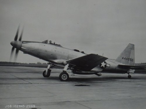
P.S. Curiously, MB-5 strongly resembles me in it's outlines and (slightly) futuristic shape another fighter - American Fisher XP-75.
WJPearce said:I think they are pretty good, but I'm biased. It can be hard getting the story right after 70 years of interpretation.
Thank you for the links!
At least, we knew, that in period of MB fighters' construction and testing they didn't go to production lines.
Is it right or wrong? We now could discuss this deciosons, but not correct them.
Perhaps, in the future someone would build one of these aircraft from scratch
P.S. Curiously, MB-5 strongly resembles me in it's outlines and (slightly) futuristic shape another fighter - American Fisher XP-75.
hole in the ground
ACCESS: Secret
- Joined
- 6 August 2008
- Messages
- 235
- Reaction score
- 23
I always thought that the xp-75 more resembled the engine testbed fairey battles
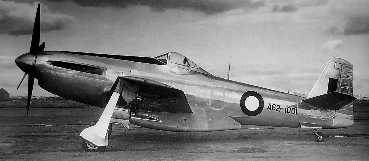
Whereas the obvious comparisons for the MB-5 are the smaller P-51 and the Aussie CAC-15


Whereas the obvious comparisons for the MB-5 are the smaller P-51 and the Aussie CAC-15
- Joined
- 1 May 2007
- Messages
- 2,595
- Reaction score
- 1,965
hole in the ground said:I always thought that the xp-75 more resembled the engine testbed fairey battles
Do you happen to know what engine is fitted to that Battle?
cheers,
Robin.
- Joined
- 6 November 2010
- Messages
- 5,263
- Reaction score
- 5,514
That's Fairey Battle K9370 fitted with a Fairey P.16 Prince. Counting eight exhaust stubs, I guess that rules out the P.24 Monarch which should show twelve stubs a side.
https://www.secretprojects.co.uk/forum/index.php/topic,986.msg7772.html#msg7772
https://www.secretprojects.co.uk/forum/index.php/topic,986.msg7772.html#msg7772
- Joined
- 6 September 2006
- Messages
- 4,834
- Reaction score
- 9,460
Even the M.B.5 had a fairly small tail fin until it was made taller. Even then the rudder is far bigger than the fixed surface.
The M.B.5 would never have been built in mass production. Martin-Baker didn't have the resources and it would have meant sub-contracting to another company, which would have meant displacing another type. The RAF by 1944 was well-stocked with fighters of good performance, both in production and in testing. The MAP was happy to leave Martin "tinkering" with the M.B.5 because it wasn't going to effect any production plans. That said, one wonders what Martin might have achieved if the MAP had harnessed his efforts into concentrating on his other projects and other non-airframe design work.
The M.B.5 would never have been built in mass production. Martin-Baker didn't have the resources and it would have meant sub-contracting to another company, which would have meant displacing another type. The RAF by 1944 was well-stocked with fighters of good performance, both in production and in testing. The MAP was happy to leave Martin "tinkering" with the M.B.5 because it wasn't going to effect any production plans. That said, one wonders what Martin might have achieved if the MAP had harnessed his efforts into concentrating on his other projects and other non-airframe design work.
hole in the ground
ACCESS: Secret
- Joined
- 6 August 2008
- Messages
- 235
- Reaction score
- 23
CJGibson said:I think he means this:
Check the caption on the first image I posted
Silencer1
That now I am the Ruler of the Queen's Navee!
- Joined
- 3 August 2009
- Messages
- 897
- Reaction score
- 582
WJPearce said:Well, there are these...
I think they are pretty good, but I'm biased. It can be hard getting the story right after 70 years of interpretation.
And again - thank you very much!
I read all three article with a great interest.
One of the links to them contains a nice selection of illustrations, covering story of Martin-Baker fighter' prototypes https://get.google.com/albumarchive/109207897425941419378/album/AF1QipMBMJ6gp_OhZWVy_uwhZinxicDlOQ-zwBOtQGQe?source=pwa
I already visits your' web-page, and it's really impress me with a huge selection of stories about powerful and unconventional piston engines. Keep up the good work!
WJPearce
ACCESS: Confidential
- Joined
- 21 March 2008
- Messages
- 63
- Reaction score
- 37
All - Glad the articles are useful and thank you for the kind words. I will keep at it. And that brings me to...
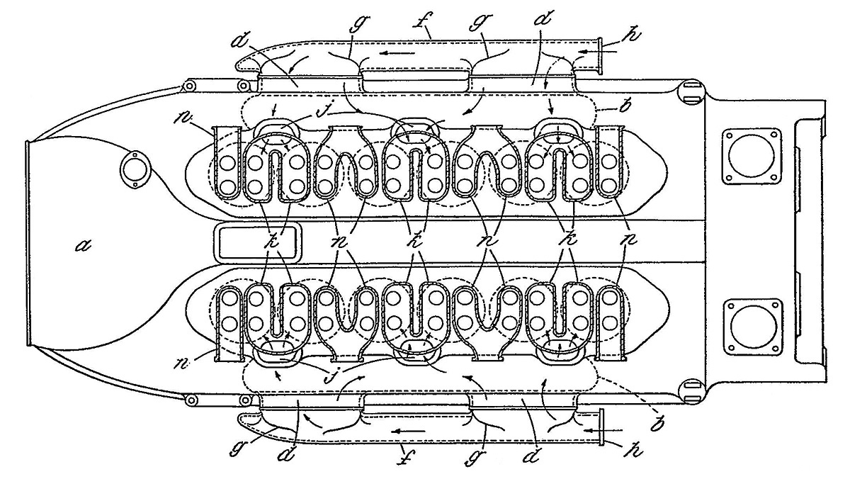
As near as I can tell, there was no P.16. The middle two exhaust stacks on the P.24 both serve two cylinders. So, the P.24 had only 16 exhaust stacks. This is one of those things where 70 years of interpretation comes into play. My attempt to cover the P.24 will be published later this month (20th). For now, below (I hope) is a drawing that shows the P.24's layout, with "n" as the exhaust. The drawing shows two exhaust valves, but the built P.24 had only one exhaust valve.
Arjen said:That's Fairey Battle K9370 fitted with a Fairey P.16 Prince. Counting eight exhaust stubs, I guess that rules out the P.24 Monarch which should show twelve stubs a side.
https://www.secretprojects.co.uk/forum/index.php/topic,986.msg7772.html#msg7772
As near as I can tell, there was no P.16. The middle two exhaust stacks on the P.24 both serve two cylinders. So, the P.24 had only 16 exhaust stacks. This is one of those things where 70 years of interpretation comes into play. My attempt to cover the P.24 will be published later this month (20th). For now, below (I hope) is a drawing that shows the P.24's layout, with "n" as the exhaust. The drawing shows two exhaust valves, but the built P.24 had only one exhaust valve.
Temistocle
ACCESS: Secret
- Joined
- 9 December 2009
- Messages
- 246
- Reaction score
- 505
Some info and a couple of pictures of MB2, from Fly Past January 1999, page 104.


- Joined
- 11 March 2012
- Messages
- 3,249
- Reaction score
- 3,179
#51
It is quite common for even diplomaed engineers to make vertical tails too small on prototypes. The deficiency is usually noticed during the first flight. I could name a long list of airplanes that quickly sprouted larger fins.
A good example is the Pilatus P-3 trainer where aerodynamicists wanted a long tail moment arm, while structural engineers wanted a short aft fuselage to save weight. Structural engineers won that debate, but soon Swiss Air Force instructors complained about poor spin characteristics. After a long series of spin tests, they added dorsal and Ventral fins. Later Pilatus trainers also added horizontal fins (LERX to horizontal stabilizer).
- Joined
- 11 March 2012
- Messages
- 3,249
- Reaction score
- 3,179
lark said:This is indeed the first unbuilt Martin MB.1 project of the early '30's.
A two seater powered by a DH Gipsy engine behind the seats.
Not quite correct as the aircraft, which may have been designated M.1 (pre Martin-Baker), was built in the Martin's Aircraft Works commencing in 1929 but never completed as funds ran out. The engine is generally said to have been a 120hp Cirrus Hermes.
The early form of the design can be seen in this 1929 patent,
That engine configuration reminds us of the current-production Stemme motorgliders. Every pilot who has flown a Stemme lands with a huge smile , beaming about the great visibility, handling, etc.
- Joined
- 11 March 2012
- Messages
- 3,249
- Reaction score
- 3,179
#33
Martin-Baker’s construction method mirrors similar systems developed by Hawker and Westland, but with fewer unique pieces. Last week I examined a “naked” Westland Lysander, but quickly lost count of the huge number of parts to build the fuselage. IOW you need a much smaller parts-catalogue to repair a MB fuselage.
Fabric covering does not limit performance until you exceed 300 miles per hour. Even end-of-War airplanes retained fabric-covered control surfaces to reduce weight and limit aerodynamic flutter.
All three systems were attempts to compensate for the shortage of skilled welders in WW2 Britain. The problem started with the British ship-building industry, but also limited tank and aircraft building.
Last edited:
- Joined
- 11 March 2012
- Messages
- 3,249
- Reaction score
- 3,179
#33
Short, stubby wings are better at low-altitude aerobatics/dog-fighting.
We can learn this from American race planes.
Consider that early races were often held at Cleveland, Ohio at only 653 feet above sea level. Early Goodyear/midget/Formula 1 racers had short, stubby wings because they were designed for similar standards to aerobatic airplanes.
When national air races moved up to Reno, Nevada at 4,400 feet above sea level, they suffered from “scrubbing off” speed during steep, high-G turns.
Later Cassett racers had their original stubby wings replaced by longer, higher aspect-ratio wings to improve lift to drag ratios in the high desert.
Unlimited, warbird racers (much-modified P-39, P-40, P-51, Bearcat, Corsair, Sea Fury, etc.) started With higher aspect-ratios than MB3 and 5. After stripping out thousands of pounds of guns, armour, old radios, long range fuel tanks, etc. they became over-winged . Most racers clipped wing tips to reduce wing areas for the heavier wing-loadings needed for higher speeds of racing.
Last edited:
The cockpit on the MB2 and MB3 was quite far back, gave good views downwards according to most descriptions I have seen, but the cockpit on the MB.5 was further forward, any reason for the change in thinking?
Also, noticed on the wiki page the MB3
With the wing flaps also pneumatically operated, the need for hydraulics, with all their attendant operational hazards and maintenance problems, was eliminated.
Is that as useful as it says and if so, did anyone else use it?
Also, noticed on the wiki page the MB3
With the wing flaps also pneumatically operated, the need for hydraulics, with all their attendant operational hazards and maintenance problems, was eliminated.
Is that as useful as it says and if so, did anyone else use it?
- Joined
- 6 September 2006
- Messages
- 4,834
- Reaction score
- 9,460
The cockpit on the MB2 and MB3 was quite far back, gave good views downwards according to most descriptions I have seen, but the cockpit on the MB.5 was further forward, any reason for the change in thinking?
Also, noticed on the wiki page the MB3
With the wing flaps also pneumatically operated, the need for hydraulics, with all their attendant operational hazards and maintenance problems, was eliminated.
Is that as useful as it says and if so, did anyone else use it?
Boulton Paul was a great believer in the use of pneumatics, the Balliol had no hydraulics and their P.119 jet trainer project likewise dispensed with hydraulics. The Handley Page HPR.2 had pneumatic flaps. The Percival Jet Provost T.1 also had an all pneumatic system, but this was removed on later variants as pneumatics proved troublesome and expensive to maintain, especially when used for undercarriage retraction. So really the fad for using pneumatics had faded by the mid/late-1950s.
nuuumannn
Cannae be ar*ed changing my personal text
- Joined
- 21 October 2011
- Messages
- 276
- Reaction score
- 547
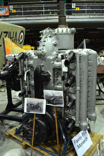
And that's confirmed on the real thing sitting in the Cobham hall at the FAA Museum, Yeovilton, with pics of the engine fitted in the Battle test bed.The middle two exhaust stacks on the P.24 both serve two cylinders. So, the P.24 had only 16 exhaust stacks.
Attachments
Similar threads
-
-

-
“The Ultimate Allied Fighters of the Second World War” by Justo Miranda
- Started by Justo Miranda
- Replies: 40
-

-
