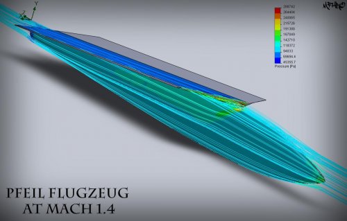
As a very rough approximation, you can assume that the drag coefficient would be calculated using any convenient reference area, and theory predicts the drag coefficient would be linear with this area. Since we don't seem to have much wing area here, I would suggest you use cross sectional area as the reference area (Cd = drag over [0.5 X rho-zero X Ve squared X ref. area]).
If we are at the same speed and altitude, rho-zero and Ve are unchanged, so your drag increases with the ratio of reference area. If your full size airplane has "x" times as much cross sectional area as the model, the full size aircraft would have "x" times as much drag. (This ignores the Reynolds number effect, but should get you within + or - 20%.)
For another quick reality check, calculate your Cd, and compare it to the typical value for a cylindrical bullet in the transonic range: usually around 0.5, based on cross-sectional area.
But - if you can build a model in Solidworks and get aerodynamic forces, why not just build a model of the full size aircraft?

")