GTX said:
Hi folks,
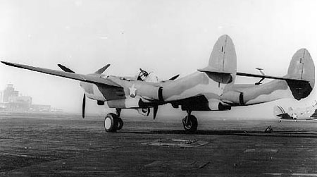
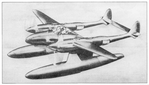
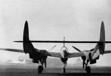
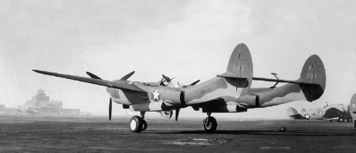
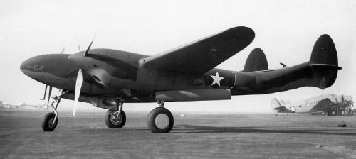
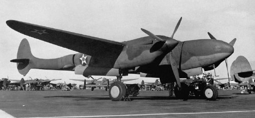
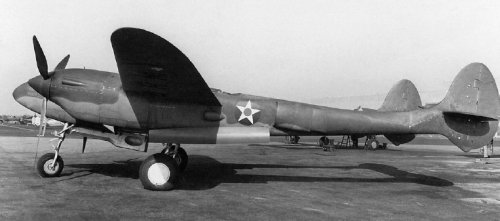
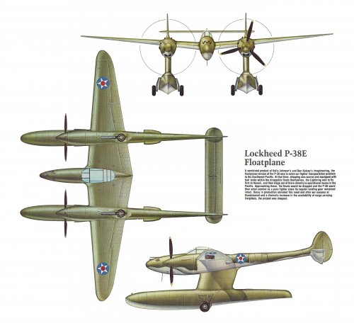
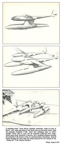
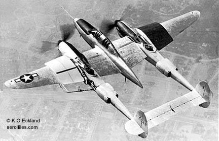
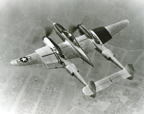
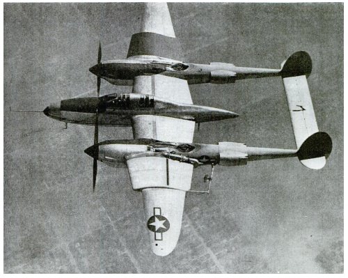
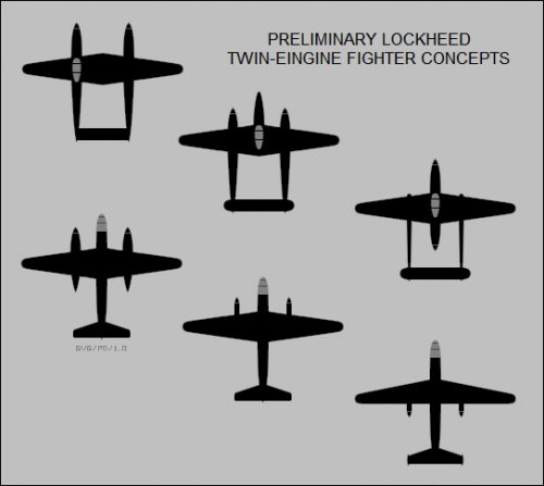
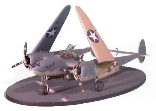
Yet another P-38 development/trial - this time in the Torpedo carrying role - apparrently two torps could be carried.
Regards,
Greg
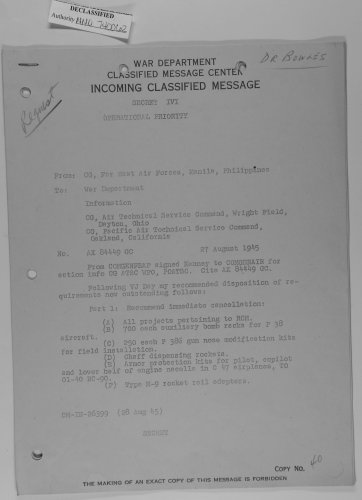
NARA II
COLLEGE PARK, MD
RG 342
ENTRY P-26
SARAH CLARK CENTRAL DECIMAL CORRESPONDENCE
BOX 3008
NND 917647
AAFMC-266-WF-6-22-42-300M
INTER-OFFICE MEMORANDUM
ARMY AIR FORCES
MATERIEL CENTER
Office of The Commanding General
JLR:fma-51
Wright Field, Dayton, Ohio
Date MAR 27 1943
E.O. 431-4-29
TO: Chief, Armament Laboratory,
Engineering Division, Wright Field
SUBJECT: Torpedo Installation on P-38G Airplanes.
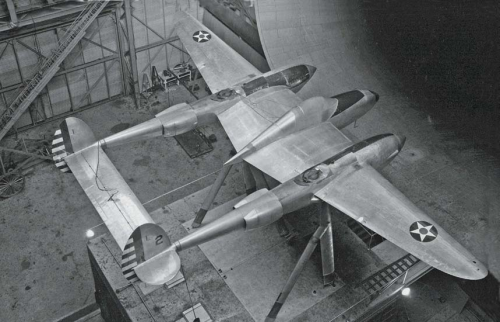
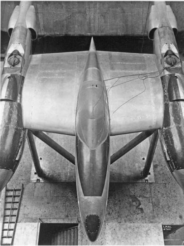
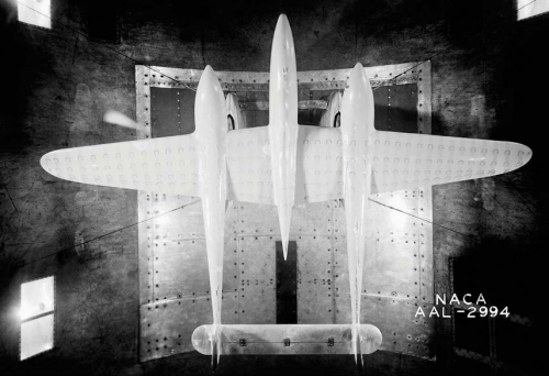
1. The installation of two 2,000-lb. torpedoes under the wing of the P-38G airplane No. 43-2381 was inspected in the Armament Hangar on March 19, 1943 by personnel of the Structures Branch, Aircraft Laboratory in answer to a telephone request from Mr. M. Burr of your Laboratory.
2. Each torpedo was slung under the wing (between the fuselage and nacelle) by means of two cables which pass under the torpedo and attach to the spars of the wing at four points, two on each spar and one of which (the outboard attachment on the front spar) is the jacking point. The cables hold the torpedo up against the standard bomb support (pedestal) which has a special fairing at the lower end to fit the contour of the torpedo. Four struts, streamlined with fairing, brace from the lower end of the pedestal to the aforementioned four cable attachment points on the wing to support the pedestal and hence the torpedo against side swaying. Two more struts braced from two of these attaching points on the wing, the ones on the rear spar, to a common point near the extreme aft end of the special pedestal fairing. This point is well aft in terms of the length of the torpedo and braces the torpedo against yawing by means of a threaded pin which screws down through, the support point and seats about three-eighths of an inch deep in a hole in the torpedo. This hole in the torpedo facilitates locating the torpedo such that its center of gravity is midway between the main support cables and directly under the pedestal-support.
3. From inspection the installation seems to be adequately supported against up or down vertical loads, against fore or aft drag loads, against side loads, and against yawing, pitching, or swaying tendencies.
4. The wing is adequately strong for the flight loads due to this installation, but not for landing with the torpedoes still on. If it becomes necessary to land with the torpedoes on, it is recommended that the pilot be cautioned to make an extremely gentle landing.
5. The question was raised as to whether or not it would adversely affect the structure to release only one of the two torpedoes. The structure would not be any more critically loaded when asymmetrically loaded with one torpedo than with two, provided the air controls and lateral balance is such that the pilot can maintain normal flight and maneuvers.
6. The above-mentioned installation is structurally satisfactory, based on visual inspection, for experimental flight testing only.
R. Frichel, Capt., A.C. for
PAUL H. KEMMER,
Colonel, Air Corps,
Chief, Aircraft Laboratory,
Engineering Division.


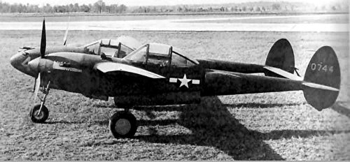
 -38E_scorpion-tail.jpg