
You are using an out of date browser. It may not display this or other websites correctly.
You should upgrade or use an alternative browser.
You should upgrade or use an alternative browser.
Kawanishi KX-03 giant 500-ton flying boat
- Thread starter Pelzig
- Start date
- Joined
- 8 March 2009
- Messages
- 1,057
- Reaction score
- 1,299
Hi guys (and girls)
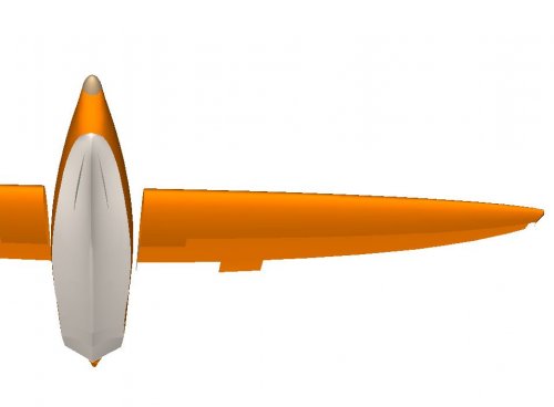
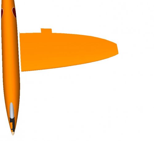
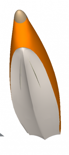
I've started to work on a 3D model of this immense aircraft. I'm basing my work of the drawing posted on the first page.
This drawing seems to indicate that it has elliptical wings, which is at odds with the Japanese illustrations posted on page 2.
Anyways I'd like some feedback on what I've done thus far. I'm trying to keep things as close to the drawing posted in this thread, as well a trying to keep things as close to what logic and guesstimation would make of this behemoth of a machine.
Keep in mind that most of this is still work in progress.
Attachments
- Joined
- 11 March 2006
- Messages
- 8,627
- Reaction score
- 3,815
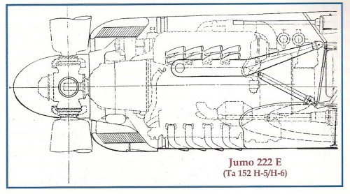
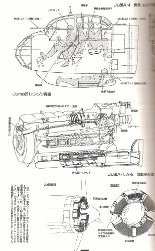
The Ju 88A series had liquid cooled engines, too, the radiators were ring shaped and placed in front of the engines,
making them look like (aircooled) radials. A fan coupled directly to the prop shaft can move a larger amount of air
at low RPM, than a prop (Raiden, Fw 190) but maybe a gear could be used, too, to drive the fan at higher speeds,
than the prop, so assuring sufficient cooling.
I've just deleted the turbine, because, as I explained, it's not my interpretation of "forced cooling".
@ sienar: Not sure, but the impression of elliptical wings in the side view, may be caused by the reduction of the
wing thickness .
Attachments
- Joined
- 11 March 2006
- Messages
- 8,627
- Reaction score
- 3,815
blackkite said:Hi!
Ta152H and Ju88. No fan.
No, but the radiator was placed directly in the slipstream of the prop, so a dedicated
fan, as in the Fw 190A series, wasn't needed.
As we said in the thread about the Fw swept-wing-pusher thread, for aircraft with a "conventional"
pull prop layout and aircooled engines, such a fan is rarely required. And the Fw 190D/Ta 152 and the
Ju 88 with Jumo 222 "mimicked" a radial engine layout and actually used the same airflow for cooling.
blackkite
Don't laugh, don't cry, don't even curse, but.....
- Joined
- 31 May 2007
- Messages
- 8,821
- Reaction score
- 7,721
Hi! We also have a another wing shape, too.sienar said:Hi guys (and girls)
I've started to work on a 3D model of this immense aircraft. I'm basing my work of the drawing posted on the first page.
This drawing seems to indicate that it has elliptical wings, which is at odds with the Japanese illustrations posted on page 2.
Anyways I'd like some feedback on what I've done thus far. I'm trying to keep things as close to the drawing posted in this thread, as well a trying to keep things as close to what logic and guesstimation would make of this behemoth of a machine.
Keep in mind that most of this is still work in progress.
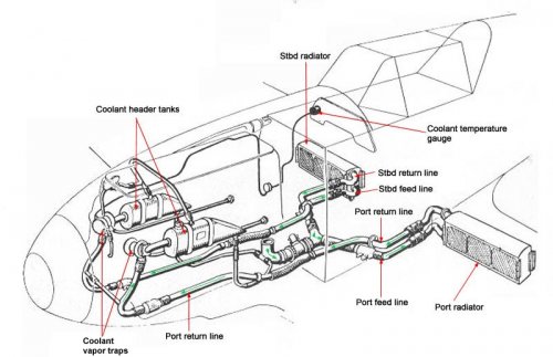
And radiator.
http://contrails.free.fr/engine_aerodyn_radia_en.php
Attachments
![Kawanishi KX-03[1].jpg](/data/attachments/75/75205-f9fe63e3f234c7892580e89e624d8d6d.jpg)
- Joined
- 11 March 2006
- Messages
- 8,627
- Reaction score
- 3,815
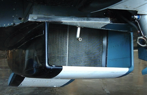
Thanks for that link, blackkite ! It may help to reconstruct the design of radiator arrangements and
so the shape of engine cowlings ! As long, of course, as the designer had this knowledge, too !")
Principally there seems to be no great differences between aircraft and car radiators, so we can use
the ones in our cars as pattern. Problem with modern cars is just, that it is extremely difficult, to get
an unobstructed view on one of the components at all !
so the shape of engine cowlings ! As long, of course, as the designer had this knowledge, too !
Principally there seems to be no great differences between aircraft and car radiators, so we can use
the ones in our cars as pattern. Problem with modern cars is just, that it is extremely difficult, to get
an unobstructed view on one of the components at all !
blackkite
Don't laugh, don't cry, don't even curse, but.....
- Joined
- 31 May 2007
- Messages
- 8,821
- Reaction score
- 7,721
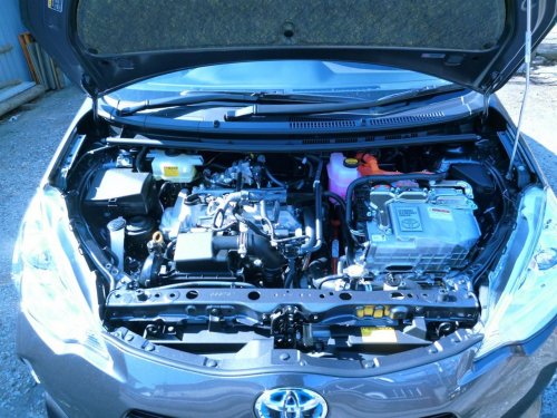
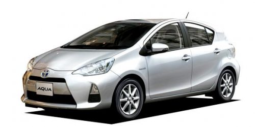
Hi! Toyota Aqua hybrid engine room. The most economical car in the world.
http://en.wikipedia.org/wiki/Toyota_Prius_c
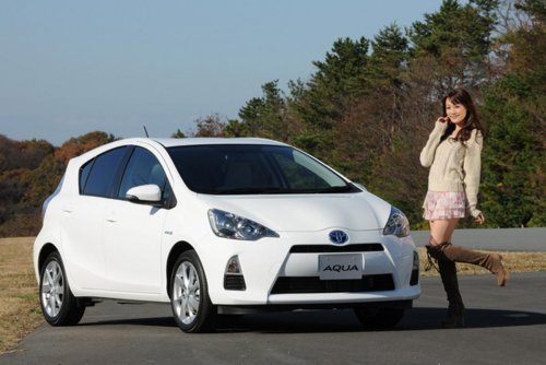
Scott how about Japanese girl? ;D Sorry off topic as usual.
http://en.wikipedia.org/wiki/Toyota_Prius_c
Scott how about Japanese girl? ;D Sorry off topic as usual.
Attachments
- Joined
- 11 March 2006
- Messages
- 8,627
- Reaction score
- 3,815
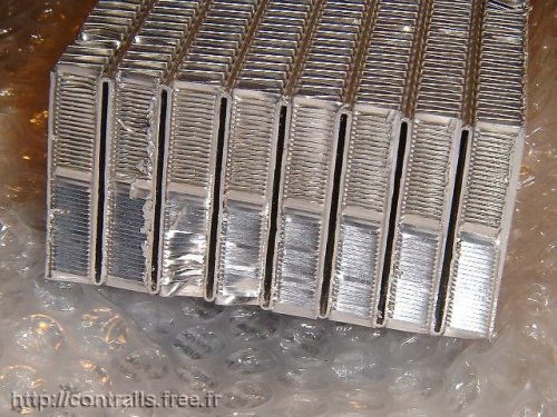
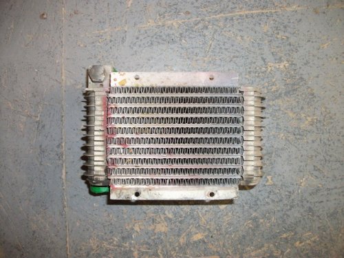
The radiator (probably of the "finned flat tube" type, similar to the Lycoming oil cooler shown below via ebay) is at
least still visible. Principally it looks like the engine bay of our car, where I always want to meet the constructor,
when I have to change a head-lamp bulb
least still visible. Principally it looks like the engine bay of our car, where I always want to meet the constructor,
when I have to change a head-lamp bulb
Attachments
Pelzig
ACCESS: Secret
- Joined
- 23 October 2008
- Messages
- 448
- Reaction score
- 82
I revisited my chapter on the K-60 flying boat based on some bits of information in Giuseppe Picarella's Japanese Experimental Transport Aircraft of the Pacific War. In doing so, I found a pattern concerning Mitsubishi and their Nu engines. The initial Mitsubishi G7M Taizan, whose design began in 1941, was to use two Nu engines. The Nu was rated at 2,200hp and was a 24-cylinder horizontal-H motor. Along comes the K-60, whose design was also initiated in 1941. Here, the engines to be used were the Mitsubishi Nu-Go which was two ME2A, 2,500hp H engines coupled together. In hindsight, I'd speculate that the Taizan's "Nu" engine was the ME2A. In both cases, it is cited that the inability of Germany to supply equipment, tools, and jigs to manufacture the engine spelled the demise of the both the initial G7M design as well as the K-60. Mitsubishi soon after let the Nu-Go die. However, they didn't quit working with horizontal-H engines and this was borne out by their Ha-203-II engine which was to power the Mitsubishi Ki-73 in 1943. Of course, they could not get the Ha-203-II to work and experienced so many problems with it, Mitsubishi canceled the engine. One can only imagine the problems the Nu-Go would have faced if Mitsubishi could not get one H engine to work, let alone two coupled together.
Nick Sumner said:I have to confess I'm a little confused by
"Nu was a combined H24 liquid cooling 2,500hp ME2A engine with steam turbine drive cooling fan"
The H24 - is this the Mitsubishi Ha 43 (Army designation - not issued a unified designation) that has been linked to the Ki 73 design that couldn't be built because the required machine tools to be sourced from Germany were unavailable?
I am completely at a loss to understand what a 'steam turbine drive cooling fan' could be.
blackkite
Don't laugh, don't cry, don't even curse, but.....
- Joined
- 31 May 2007
- Messages
- 8,821
- Reaction score
- 7,721
Hi ED!
As you already knew, it's hard for Japan to manufacture and use liquid cooling engine at the day, because Japanese engine makers could not use Nickel for liquid cooling engine crank shaft material by the IJA and the IJN's order. Japan did not have enough Nickel at the day. Some Hien's HA-40(DB601) engine crank shaft broke only 80 hours use. Japan tried to get New Caledonia's Nickel and failed at the begining of the war.
http://en.wikipedia.org/wiki/Nickel
Attachments
Pelzig
ACCESS: Secret
- Joined
- 23 October 2008
- Messages
- 448
- Reaction score
- 82
Quite so. I just find it curious that Mitsubishi continued to tinker as long as they did with the H engine which was a much more complex animal than a more conventional inline liquid-cooled engine.
blackkite said:Hi ED!
As you already knew, it's hard for Japan to manufacture and use liquid cooling engine at the day, because Japanese engine makers could not use Nickel for liquid cooling engine crank shaft material by the IJA and the IJN's order. Japan did not have enough Nickel at the day. Some Hien's HA-40(DB601) engine crank shaft broke only 80 hours use. Japan tried to get New Caledonia's Nickel and failed at the begining of the war.
http://en.wikipedia.org/wiki/Nickel
- Joined
- 11 February 2007
- Messages
- 2,580
- Reaction score
- 4,407
'steam-turbine drive cooling fan' is definitely an interesting term. If it isn't simply a mistaken reference to using an exhaust turbine to drive a cooling fan rather than a turbocharger, then we need a steam source from somewhere and I see two options:
1) With an evaporative cooling system you could put the turbine between the engine steam outlet and the radiator inlet.
2) With a conventional liquid cooling system the only practical steam source I can see is a heat-exchanger buried in the radiator, which could actually be a very elegant design, using the radiator to power its own cooling fan, which should both increase its thermal efficiency and be largely self-regulating.
- Joined
- 11 February 2007
- Messages
- 2,580
- Reaction score
- 4,407
The difference isn't always clear, I had at least two full-blown projects in my career (support stuff in both cases rather than actual avionics) where I did the design study and then recommended we not proceed any further. I also worked on a full-scale FBW development project (757RT) which was initially conceived as flying, but in the end never went further than the iron bird, that in turn was an outgrowth of earlier 7J7 conceptual work, and was itself the prototype for the 777 FBW system. The interesting thing with the 7J7 to 757-RT to 777 work was the evolution to a simpler design as we got feedback from FAA on what was an acceptable level of redundancy. IOW the design studies are just as important as the flying hardware if you want to understand the way that designs evolve.windswords said:Not to nitpick, but does a "design study" qualify as a project? I would think a project would be a one whose purpose was to build an actual aircraft.
Getting back to the KX-03, people have commented that surely the IJN knew this couldn't be built - not until they had done the design study they didn't! By 1943 the IJN was facing two distinct strategic problems: 1) getting oil back from the oil fields in the Netherlands East Indies to the Home Islands; 2) getting supplies out to the Pacific outposts. In both cases the supply routes were being interdicted by the US submarine offensive, and going over them rather than past them was a possibility we know was explored. If you're going to build aircraft for those supply runs, then it makes sense to build them as large as possible, because of efficiencies of scale. If nothing else the bigger the aircraft, the fewer pilots you need per tonne of cargo carried (and large-scale pilot training was another Japanese weakness). So it makes complete sense for the IJN to explore just what the physical limits were on flying boat construction.
For a relatively recent parallel, look at the Boeing Pelican, an airlifter with a 1,400t cargo capacity. That's startling even by contemporary standards, but Boeing were seriously looking at it because it potentially solved DoD's problems with the sheer number of sorties needed for rapid troop-lift into an operational theatre.
blackkite
Don't laugh, don't cry, don't even curse, but.....
- Joined
- 31 May 2007
- Messages
- 8,821
- Reaction score
- 7,721
Hi DWG!DWG said:'steam-turbine drive cooling fan' is definitely an interesting term. If it isn't simply a mistaken reference to using an exhaust turbine to drive a cooling fan rather than a turbocharger, then we need a steam source from somewhere and I see two options:
1) With an evaporative cooling system you could put the turbine between the engine steam outlet and the radiator inlet.
2) With a conventional liquid cooling system the only practical steam source I can see is a heat-exchanger buried in the radiator, which could actually be a very elegant design, using the radiator to power its own cooling fan, which should both increase its thermal efficiency and be largely self-regulating.
Please show me the flow diagram of your idea. Do you want to use the engine as a steam generator same as the BWR nuclear reactor?
I think this idea is something like a skin cooler(Steam surface radiator).
For Japan, it was very hard to realize high temperature exhaust turbine at the day.
Attachments

blackkite
Don't laugh, don't cry, don't even curse, but.....
- Joined
- 31 May 2007
- Messages
- 8,821
- Reaction score
- 7,721
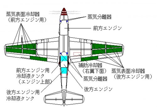
Kawasaki Ki-64's engines were cooled by pressuzired (3at) water. The flow route of engine cooling system was as follows.
Engine cooling jaket→Reducing valve(some portion of cooling water evaporated through reducing valve) →steam separator→steam/water
Steam→Steam surface radiator(condensor)→pump→Auxiliary radiator→Engine cooling jaket.......
Water→pump→Auxiliary radiator→Engine cooling jaket.......
This cooling system was based of imported Heinkel He100 and He119's system.
蒸気分離器 : Steam separator, 補助冷却器 : Auxiliary radiator, 蒸気表面冷却器 : Steam surface radiator, 冷却液タンク :Cooling liquid tank,
前方エンジン: Front engine, 後方エンジン : Rear engine
http://www.geocities.jp/rxp05513/jyo-kyo001_200.htm
This system's performance was not sufficient when ground engine test/taxing and climb.
When ground engine test/taxing and climb, steam discharged and cooling water was supplied from water tank.
I think that Nu engine cooling system operating pressure may be larger than 3at, around 10at(1Mpa) to keep steam turbine operating pressure.
Sorry for off topic as usual. ;D
Attachments
-
 p_51vski_640.jpg18.9 KB · Views: 93
 -
 jyo_kyo001206001.jpg24.6 KB · Views: 108
 -
 jyo_kyo001205001.jpg20.1 KB · Views: 115
 -
 jyo_kyo001203001.jpg117.3 KB · Views: 601
 -
 jyo_kyo001202001.jpg29.2 KB · Views: 630
 -
 jyo_kyo001201001.jpg22.7 KB · Views: 662
 -
 ki64.gif5 KB · Views: 683
 -
 Ki-64.jpg115.9 KB · Views: 757
Pelzig
ACCESS: Secret
- Joined
- 23 October 2008
- Messages
- 448
- Reaction score
- 82
I actually kicked this around. It took four Kasei 22 engines at 1,850hp at take-off to move the H11K Soku around. Fully loaded, the Soku was 50 tons. At face value, at 500 tons, you'd need ten Kasei 22 for the KX-3. The Ne 201 appeared, at least in theory, in 1942. Turboprops were more efficient and the estimated 1,870hp of the Ne 201 was comparable to the Kasei 22. So, they aren't far off. I suspect the six Ne 330 were more for additional thrust on take-off or speed boosts rather than being run constantly. The estimated fuel consumption was horrific in the Ne 330. Sure, you have 500 tons to play with for fuel. To kick the K-200 around for an hour would take 33,000+ pounds of fuel if all six Ne 330 engines were run at full power. Asides, the Ne 20 could be run, at best, 4-5 hours before it began to fall apart. Mitsubishi never got their Ne 330 built so who can say how reliable it would have been.
I found a reference to the KX-2, also the K-90, mentioned in conjunction with the Kawanishi J3K1.
As a side, the Kawanishi K-10 was the E15K and K-20 was the N1K. The KX-1 was the K-100.
I found a reference to the KX-2, also the K-90, mentioned in conjunction with the Kawanishi J3K1.
As a side, the Kawanishi K-10 was the E15K and K-20 was the N1K. The KX-1 was the K-100.
blackkite said:According to “もしもWEAPON”, the source of KX-03 are Kawanishi aircraft's technical report No541,544,566 ”500ton class flying boat study. The IJN ordered Kawanishi to study 500 ton class flying boat in the beginning of 1943.
Overall length;162m, Span;180m, Height;35.4m, Wing area;1,150square meter,
Gross weight;460ton, Range;18,520km, Payload;900 soldiers with normal equipments,
Engines; Ne201 turbo prop engine(7,000hp + static thrust 900kg/each engine)×12(total 132,000hp),
Ne330 jet engine×6(total equivalent 7,920hp), crews;24.
Ed! How about cover this study in your next work?
BTW according to another book"Kikka (miki shobo) ISBN4-89522-276-4 C0053 " Ne201's power was 1,870hp.(7,000hp is too large for Ne201,)
I think Ne201 was not applied this study. The engine of this study might be another secret studied engine.
I believe also KX-01 nad KX-02 were studied. I can't imagine what aircrafts were. (flying boat?)
- Joined
- 1 February 2011
- Messages
- 2,941
- Reaction score
- 3,625
About these turboprops.
Does they are a development purely by Japanese engineers from normal piston and jet engines, or is it possible that they got documentations from the Hungarian Engineer György Jendrassik and his (World first) Cs-1 Turboprop engine???
Does they are a development purely by Japanese engineers from normal piston and jet engines, or is it possible that they got documentations from the Hungarian Engineer György Jendrassik and his (World first) Cs-1 Turboprop engine???
Pelzig
ACCESS: Secret
- Joined
- 23 October 2008
- Messages
- 448
- Reaction score
- 82
If I am reading Kazuhiko Ishizawa's flow chart right in his book "Kikka:The Technological Verification of the First Japanese Jet Engine Ne 20", it seems to show that the Ne 201 turboprop was at least discussed back in 1942 along with the fledgling jets. But, the interest was more on turbojets and interest in the Ne 201 fell by the wayside. Blakkite might be able to shed some light as I believe he has this book.
And yes, turboprops were patented before WW2 even started so, certainly the Japanese were aware of them.
And yes, turboprops were patented before WW2 even started so, certainly the Japanese were aware of them.
Tzoli said:About these turboprops.
Does they are a development purely by Japanese engineers from normal piston and jet engines, or is it possible that they got documentations from the Hungarian Engineer György Jendrassik and his (World first) Cs-1 Turboprop engine???
- Joined
- 1 February 2011
- Messages
- 2,941
- Reaction score
- 3,625
Hikoki1946 said:If I am reading Kazuhiko Ishizawa's flow chart right in his book "Kikka:The Technological Verification of the First Japanese Jet Engine Ne 20", it seems to show that the Ne 201 turboprop was at least discussed back in 1942 along with the fledgling jets. But, the interest was more on turbojets and interest in the Ne 201 fell by the wayside. Blakkite might be able to shed some light as I believe he has this book.
And yes, turboprops were patented before WW2 even started so, certainly the Japanese were aware of them.
That is probably true that they know of the concept and the patent, but a Hungarian developed the first working one in 1938-40. This was my question that if the Japanese had any documentation about the Cs-1
Pelzig
ACCESS: Secret
- Joined
- 23 October 2008
- Messages
- 448
- Reaction score
- 82
Hard to say. Possible. I have a photograph that shows a Japanese observer with the Hungarian army in WW2 in Russia. Was there more than just observers? Not sure.
Photo from the Hungarian book "Hadak Utjan"
Photo from the Hungarian book "Hadak Utjan"
Tzoli said:Hikoki1946 said:If I am reading Kazuhiko Ishizawa's flow chart right in his book "Kikka:The Technological Verification of the First Japanese Jet Engine Ne 20", it seems to show that the Ne 201 turboprop was at least discussed back in 1942 along with the fledgling jets. But, the interest was more on turbojets and interest in the Ne 201 fell by the wayside. Blakkite might be able to shed some light as I believe he has this book.
And yes, turboprops were patented before WW2 even started so, certainly the Japanese were aware of them.
That is probably true that they know of the concept and the patent, but a Hungarian developed the first working one in 1938-40. This was my question that if the Japanese had any documentation about the Cs-1
Attachments

blackkite
Don't laugh, don't cry, don't even curse, but.....
- Joined
- 31 May 2007
- Messages
- 8,821
- Reaction score
- 7,721
Yes I have the book of Kikka/Ne20 jet engine.Hikoki1946 said:If I am reading Kazuhiko Ishizawa's flow chart right in his book "Kikka:The Technological Verification of the First Japanese Jet Engine Ne 20", it seems to show that the Ne 201 turboprop was at least discussed back in 1942 along with the fledgling jets. But, the interest was more on turbojets and interest in the Ne 201 fell by the wayside. Blakkite might be able to shed some light as I believe he has this book.
And yes, turboprops were patented before WW2 even started so, certainly the Japanese were aware of them.
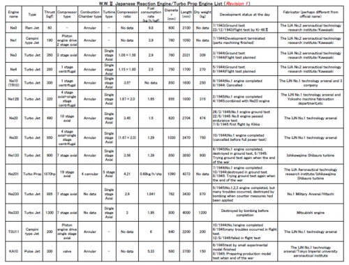
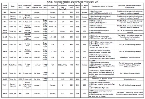
Ne201 was a turbo prop engine which had 1870hp shaft power.(Maker : The IJA aeronautical technology research institute/Ishikawajima Shibaura turbine.)
The basic design of Ne201 was done by Tokyo imperial university, the IJA ordered Hitachi to develop this engine but Hitachi rejected ;D , then Ishikawajima Shibaura turbine received the order to develop this engine.
7/1944 : The first engine was completed.
10/1944 : The first engine was destroyed in ground test.
8/1945 : The ground test had been trying again when the end of the war.
So the JJA did not give up to develop Ne201 turboprop engine.
Ne201-Ⅱ was a turbojet variant of Ne201 engine , later became Ne130 turbojet engine which had 900kg thrust.
THe first Ne130 was complted in 6/1945, destroyed in ground test in 8/1945.(Maker : Ishikawajima Shibaura turbine)
I believe that the gas generator(compressor/turbine) of Ne201 engine was almost same shape of Ne130 engine.
I will make table and chart for these Japanese gas turbine engine. Give me time.
blackkite
Don't laugh, don't cry, don't even curse, but.....
- Joined
- 31 May 2007
- Messages
- 8,821
- Reaction score
- 7,721
blackkite
Don't laugh, don't cry, don't even curse, but.....
- Joined
- 31 May 2007
- Messages
- 8,821
- Reaction score
- 7,721
Good question! Give me time.Tzoli said:About the Turboprop engines.
Compared to an equal power Piston engine let's say 2000hp, do they use less fuel? Or needs smaller space?
famvburg
I really should change my personal text
- Joined
- 24 July 2011
- Messages
- 386
- Reaction score
- 54
Butting in, maybe, but I think it would depend on engines. For example, the Cavalier Turbo Mustang III that was converted from a Merlin to a Dart, both engines took a similar amount of room but the Dart was thirstier, by how much I don't know. A comparison I did about 25 years ago when the guy my dad flew cropdusters for was looking at switching from an R-1340 powered Air Tractor to a PT-6 powered one came up with these basics. The R-1340, prop and accessories weighs about 1500 lbs and on a good day puts out 600 HP and burns about 35 GPH. OTOH, a PT-6 (I forget the particular dash model, but probably like a -21 or -26) rated at 600 HP weighs about 350 lbs, prop and accessories included. It burns about 50 GPH.
blackkite
Don't laugh, don't cry, don't even curse, but.....
- Joined
- 31 May 2007
- Messages
- 8,821
- Reaction score
- 7,721
Hi! Ne-201 turbo prop engine. Turbine output : 6720hp, Required compressor drive power : 4850hp, So Propeller drive power=6720hp-4850hp=1870hp.
Propeller drive power 7000hp class is apparently mistake. Additional jet thrust is 600kg.
Planned operating altitude :8000m, Planned operationg speed : 900km/h. Fuel consumption : 1280kg/h.
Ne-204 was a Ne-201 development and practical type.

Propeller drive power 7000hp class is apparently mistake. Additional jet thrust is 600kg.
Planned operating altitude :8000m, Planned operationg speed : 900km/h. Fuel consumption : 1280kg/h.
Ne-204 was a Ne-201 development and practical type.

Last edited:
blackkite
Don't laugh, don't cry, don't even curse, but.....
- Joined
- 31 May 2007
- Messages
- 8,821
- Reaction score
- 7,721
It's true that Kawanishi studied 100ton-500ton class aircraft.
Kawanishi designed 500ton class flying boat, and did wind tunnel test and water tank test(towing test or circulating water tank test?).
And confirm the possibility of 68ton payload, 200kt speed and 2000n.m.range.
Same study were also conducted by Osaka Imperial University and Tokyo University of Engineering.
Source : 日本航空学術史(1910-1945)
Last edited:

blackkite
Don't laugh, don't cry, don't even curse, but.....
- Joined
- 31 May 2007
- Messages
- 8,821
- Reaction score
- 7,721
This picture is too terrible. It is an impossible picture. It's a over 3000 ton class flying boat. C-5B MTOW is 380ton.
According to this drawing, KX-03 span is around 190m, length is around 160m.

According to this drawing, KX-03 span is around 190m, length is around 160m.

Last edited:
blackkite
Don't laugh, don't cry, don't even curse, but.....
- Joined
- 31 May 2007
- Messages
- 8,821
- Reaction score
- 7,721
Hughes H-4
General characteristics
General characteristics
- Length: 218 ft 8 in (66.65 m)
- Wingspan: 320 ft 11 in (97.54 m)
- Height: 79 ft 4 in (24.18 m)
- Fuselage height: 30 ft (9.1 m)
- Empty weight: 250,000 lb (113,399 kg)
- Loaded weight: 400,000 lb (180,000 kg)
- Powerplant: 8 × Pratt & Whitney R-4360 Wasp Major radial engines, 3,000 hp (2,640 kW) each
- Propellers: four-bladed Hamilton Standard, prop, one per engine
- Propeller diameter: 17 ft 2 in (5.23 m)
- Cruise speed: 250 mph (407.98 km/h)
- Range: 3,000 mi (4,800 km)
- Service ceiling: 20,900 ft (6,370 m)
Last edited:
blackkite
Don't laugh, don't cry, don't even curse, but.....
- Joined
- 31 May 2007
- Messages
- 8,821
- Reaction score
- 7,721
500/180=2.78, Cube root 2.78=1.4
So perhaps KX-03 Length was around 93m, KX-03 wig span was around 136m.
Ne201×12 : 1870×12=22440hp. 22440+15230(equivalent power of Ne330, 1300kg thrust×6+Ne201, 600kg thrust×12)=37670hp(based of Ed-san's information)
KX-03 required power based on H-4 power : 24000hp×2.78=66720hp if power loading was same value.
H-4 : 3000×8=24000HP
So Ne201×12+Ne330×6 are not enough.
KX-03 Required engines were Ne201×22+Ne330×12(minimum!)
If KX-03 used 5000hp Nu engine, required Nu engine was 12 and Ne330 jet enginr was 6.
Last edited:
zemmix
It said I really should change my personal text
- Joined
- 22 March 2012
- Messages
- 1
- Reaction score
- 3
View: https://www.facebook.com/mikro.mir.dnepr/posts/3427657923978586

1/350 scale kit of this monster on the way from MikroMir

1/350 scale kit of this monster on the way from MikroMir
- Joined
- 18 June 2009
- Messages
- 1,412
- Reaction score
- 2,494
In terms of powering this beastie. A large central engine may power electric motors on the wing in distributed lift…but could the small electric nacelles also have a fuel burning component in their aft section?
Similar threads
-
-

-
 IJN Service Airplane Development Program Designations
- Started by snark
- Replies: 7
-
 American Report about Kawasaki Aircraft Industries Company Inc
- Started by airman
- Replies: 2
-