Inward-turning Inlets

Sundog said:
I believe that TRINT is the same inlet, or very close to the same inlet shown in the Wind Tunnel mag link above on pages 15 and 106 for the FALCON program.

These designs come from quite different entities for different requirements. The FaCET design comes from LMart and the TRINT is a truncated design from JHU-APL. Any coincidence is just due to the fact that these are both modied Buseman type inlets.
 
http://www.freepatentsonline.com/8292217.html

Hypersonic inlet systems and methods Document Type and Number: United States Patent 8292217
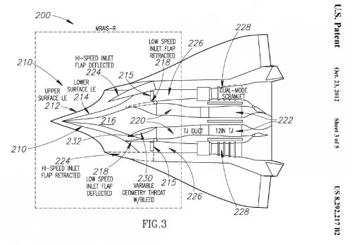
Abstract: Hypersonic inlet systems and methods are disclosed. In one embodiment, an inlet for an airbreathing propulsion system includes an inboard surface at least partially shaped to conform to a plurality of streamline-traces of a design flowfield approaching an aperture, an outboard surface spaced apart from the inboard surface, an upper surface extending between the inboard and outboard surfaces, and a lower surface extending between the inboard and outboard surfaces, wherein leading edges of the inboard, outboard, upper, and lower surfaces cooperatively define the aperture.

Inventors: Smith, Thomas R. (Westminster, CA, US)
Espinosa, Angel M. (St. Charles, MO, US)
Farrell, Daniel J. (St. Louis, MO, US)
Robertson, Andrew (West Sayville, NY, US)
Leylegian, John C. (White Plains, NY, US)
Tyll, Jason S. (Blue Point, NY, US)
Girlea, Florin (Flushing, NY, US)
Alifano, Joseph A. (Ronkonkoma, NY, US)
Chue, Randy S. M. (Bohemia, NY, US)

Application Number: 12/133289 Publication Date: 10/23/2012 Filing Date: 06/04/2008 View Patent Images: Download PDF 8292217 PDF help Export Citation: Click for automatic bibliography generation Assignee: The Boeing Company (Chicago, IL, US)
 

Attachments

  • fig_3.jpg
    fig_3.jpg
    126.3 KB · Views: 88
Semi off-topic, but who knew there was a Boeing-related design team on Long Island.
 
George Allegrezza said:
Semi off-topic, but who knew there was a Boeing-related design team on Long Island.

Not part of Boeing, but ATK-GASL or whatever part of ATK they may have now become part of.
 
Ah yes, how could I forget? Beautiful downtown Ronkonkoma or thereabouts.
 
http://www.secretprojects.co.uk/forum/index.php/topic,4164.msg32809.html#msg32809
 
err, you are right
whatever, we have moar or higher quality pics now, especially if you'll check tiff files at USPTO
 
Sannu Molder's presentation at last month's AIAA Spaceplanes Conference.
Sannu Molder, Ryerson Polytechnic University, "WaveCatcher Intakes for Scramjets" (PDF)
 
DSE said:
Sannu Molder's presentation at last month's AIAA Spaceplanes Conference.
Sannu Molder, Ryerson Polytechnic University, "WaveCatcher Intakes for Scramjets" (PDF)

Thanks DSE!
On quick inspection, I see some photos Sannu allowed us to publish here in the past.
Looking forward to reading it.
Been too busy designing CPUs of late.
 
When was it first possible to make a truly feasible inward turning ramjet that would work better than the 2D waveriders?
 
CaseyKnight said:
When was it first possible to make a truly feasible inward turning ramjet that would work better than the 2D waveriders?

Adolf Busemann pubished his paper on axisymmetric inlet design in 1942. "Die achsensymmetrische kegeligeUeber-schallstromung". In Luftfahrtforschung 19, May 1942
This paper is still referenced today.

The earliest actual inward turning scramjet inlet designs, actually fabricated and test flown
(unsuccessfully unfortunately due to the disintegration of the test vehicle due to the
high g-loading caused by firing them out of a US Navy 16-in naval rifle) were associated
with the suborbital gun launched scramjet vehicle tests of Project HARP in 1966 or so.
We have published some pictures of these vehicles and their inlets here on this list:
http://www.secretprojects.co.uk/forum/index.php/topic,12168.msg118734.html#msg118734

They ran out of money before they could get to the 30 or so test flights needed to get
the scramjet test vehicles to survive firing them out of a gun.

So this inlet technolgy has been around for a long time.

And this is not to say that 2-D inlets don't work, especially for a point design like a waverider
where it wants to cruise at a specific Mach number. Many of the leading waverider papers were
done with 2-D inlet designs.
 
shockonlip


I read the Project HARP data: I'm surprised such an inlet was developed that long ago and a scramjet nonetheless (a ramjet would presumably be easier).


Though I've seen many 2D waverider designs that were from the 1980's (X-30, Orient Express) and so on, it was my assumption that the 3D designs weren't developed until later because of the means to make it work. I guess if a 2D design is efficient enough (and easier to develop) it makes sense why they'd have done so much research around that arrangement.


Since I have not been able to get data on hypersonics online, I'm curious as to two things provided they aren't classified


1.) Did the inward turning inlets provided solely inlet efficiency improvements at hypersonic speeds or also improved L/D ratios as well?
2.) How much extra inlet efficiency was produced over earlier designs at mach numbers between 5-10?
 
shockonlip said:
Adolf Busemann pubished his paper on axisymmetric inlet design in 1942. "Die achsensymmetrische kegeligeUeber-schallstromung". In Luftfahrtforschung 19, May 1942
This paper is still referenced today.

The earliest actual inward turning scramjet inlet designs, actually fabricated and test flown
(unsuccessfully unfortunately due to the disintegration of the test vehicle due to the
high g-loading caused by firing them out of a US Navy 16-in naval rifle) were associated
with the suborbital gun launched scramjet vehicle tests of Project HARP in 1966 or so.
We have published some pictures of these vehicles and their inlets here on this list:
http://www.secretprojects.co.uk/forum/index.php/topic,12168.msg118734.html#msg118734

They ran out of money before they could get to the 30 or so test flights needed to get
the scramjet test vehicles to survive firing them out of a gun.

So this inlet technolgy has been around for a long time.

And this is not to say that 2-D inlets don't work, especially for a point design like a waverider
where it wants to cruise at a specific Mach number. Many of the leading waverider papers were
done with 2-D inlet designs.

Is the defining characteristic of the "inward-turning inlets" simply that they are rounded on the top and bottom surface instead of flat? How would that improve performance?

Bob Clark
 
RGClark said:
Is the defining characteristic of the "inward-turning inlets" simply that they are rounded on the top and bottom surface instead of flat? How would that improve performance?

It means what it says. The flow is (always) turned inward towards the flow axis, not away. It isn't necessarily the fact that the flow is turned inwards that can lead to improved performance. It is the fact that a high efficiency compression field is used.

"The Busemann inlet flowfield is an inviscid inward turning axisymmetric flowfield that terminates in a conical shock wave. At the design Mach number, the compression upstream of the conical shock wave is isentropic and the flow down-stream is uniform. The conical shock wave is the only entropy producing feature of inviscid design. The resulting inviscid compression efficiency is
remarkably higher than other classes of inlets."

Note the key points here are inviscid and the true Busemann is quite long. Truncated Busemanns shorten the inlet at the expense of isentropic compression. Then viscous effects need to be dealt with.
 
KJ_Lesnick said:
Though I've seen many 2D waverider designs that were from the 1980's (X-30, Orient Express) and so on, it was my assumption that the 3D designs weren't developed until later because of the means to make it work. I guess if a 2D design is efficient enough (and easier to develop) it makes sense why they'd have done so much research around that arrangement.

Since I have not been able to get data on hypersonics online, I'm curious as to two things provided they aren't classified


1.) Did the inward turning inlets provided solely inlet efficiency improvements at hypersonic speeds or also improved L/D ratios as well?
2.) How much extra inlet efficiency was produced over earlier designs at mach numbers between 5-10?

One needs to be careful about one uses the terms waverider, lifting body, inward-turning, streamline traced, etc. They are have very specific meanings, however many throw them around quite cavalierly. The final X-30 vehicles were lifting bodies as were the Hyper-X research vehicles, not waveriders. Similarly some inward-turning inlets are streamline traced, many are not. The devil is in the details and it does make a difference.

Lots of data is available on-line, not sure what the problem is. See Fig 13 of http://hapb-www.larc.nasa.gov/Public/Documents/Aiaa-5459454.pdf. for instance. Other earlier papers by Smart can be found at the bottom of http://hapb-www.larc.nasa.gov/Public/Engines/Rest/Rest.html
 
DSE


Honestly, I feel as if I'm in over my head here so please try to bear with me, I'm not trying to sound retarded (Though I assume I probably am)


It means what it says. The flow is (always) turned inward towards the flow axis, not away.
Like a scoop?


It isn't necessarily the fact that the flow is turned inwards that can lead to improved performance. It is the fact that a high efficiency compression field is used.
I thought a high efficiency flow field was produced by using a gradual curvature to the duct to produce a whole bunch of weak shockwaves (and ideally a fan-shock) rather than a few or one powerful one(s).


The Busemann inlet flowfield is an inviscid inward turning axisymmetric flowfield that terminates in a conical shock wave.
At the penalty of sounding positively retarded why is a conical shock desired?


At the design Mach number, the compression upstream of the conical shock wave is isentropic and the flow down-stream is uniform. The conical shock wave is the only entropy producing feature of inviscid design.
I'm more of a conceptual person so I'm trying to break this into concepts, please tell me if I'm right here: The idea is to drive up the pressure and density of the inlet with as close to no change in entropy and no viscosity which produces the theoretical minimum loss of inlet performance to turbulent flow and heat?


One needs to be careful about one uses the terms waverider, lifting body, inward-turning, streamline traced, etc. They are have very specific meanings, however many throw them around quite cavalierly. The final X-30 vehicles were lifting bodies as were the Hyper-X research vehicles, not waverers.
That blew my mind -- if the X-30 and X-43 aren't wave-riders, what is a wave-rider?


Similarly some inward-turning inlets are streamline traced
So with that being said I would assume
1: Streamline-traced inlet: The inlet shape is carved into the shape of the aircraft based on the airflow pattern to form the desired inlet?
2: Streamline-traced inlets aren't intrinsically inward-turning inlets?
 
KJ_Lesnick said:
DSE

Honestly, I feel as if I'm in over my head here so please try to bear with me, I'm not trying to sound retarded (Though I assume I probably am)


It means what it says. The flow is (always) turned inward towards the flow axis, not away.
Like a scoop?

In a way yes. The term inward-turning is typically associated with sugar scoop looking inlets with no forebody compression in front. However, any internal compression would also seem to fit the general description. One reason many in the field don't like the term.

It isn't necessarily the fact that the flow is turned inwards that can lead to improved performance. It is the fact that a high efficiency compression field is used.
I thought a high efficiency flow field was produced by using a gradual curvature to the duct to produce a whole bunch of weak shockwaves (and ideally a fan-shock) rather than a few or one powerful one(s).


The Busemann inlet flowfield is an inviscid inward turning axisymmetric flowfield that terminates in a conical shock wave.
At the penalty of sounding positively retarded why is a conical shock desired?

The Busemann flowfield is an axisymmetric isentropic compression. That's the high efficiency part. However, at the end of that compression field the flow must finally be turned to follow the axis of the duct, that is done in the terminating shock. While shocks are lossy this is now at lower Mach # so the loss is smaller. In real inlets truncated Busemann's have a an initial finite thickness wedge at the beginning where the isentropic contour has been truncated in length to shorten the inlet and minimize viscous losses. Remember all this talk of isentropic compression is for an inviscid flowfield.

At the design Mach number, the compression upstream of the conical shock wave is isentropic and the flow down-stream is uniform. The conical shock wave is the only entropy producing feature of inviscid design.
I'm more of a conceptual person so I'm trying to break this into concepts, please tell me if I'm right here: The idea is to drive up the pressure and density of the inlet with as close to no change in entropy and no viscosity which produces the theoretical minimum loss of inlet performance to turbulent flow and heat?

In theory, yes. In practice that always requires compromises for other design issues. Inlet starting and operating under a significant back pressure are two key important ones.

One needs to be careful about one uses the terms waverider, lifting body, inward-turning, streamline traced, etc. They are have very specific meanings, however many throw them around quite cavalierly. The final X-30 vehicles were lifting bodies as were the Hyper-X research vehicles, not waverers.
That blew my mind -- if the X-30 and X-43 aren't wave-riders, what is a wave-rider?

A lifting body is an airframe form which is designed to use the undersurface compression field to provide a substantial portion of overall lift. A waverider is a much more restrictive design where the vehicle shape is determined to fully capture the undersurface shock at the design conditions (Mach, AoA). Somewhat analagous to the fact there can be many types of compression flowfields, however a specifically restrictive case of that is an isentropic compression field.

Similarly some inward-turning inlets are streamline traced
So with that being said I would assume
1: Streamline-traced inlet: The inlet shape is carved into the shape of the aircraft based on the airflow pattern to form the desired inlet?
2: Streamline-traced inlets aren't intrinsically inward-turning inlets?

Streamline-traced inlets are traced from some other apriori defined compression field. See the paper by Smart refereneced earlier. If they are all internal compression then they are called inward turning. Several of the newer design techniques also employ some other shaping of the flow. the REST design by Smart for instances has a rectangular capture are but an elliptical throat. The design is multi-step tracing downstream from the capture shape and upstream from the throat shape with some lofting technique to eventually combine the shapes into one. This is not strictly a streamline traced inlet and I like the term quasi-streamlined traced used by Smart to denote the difference. As always the devil is in the details.


Added 7-2-2013: See this reference for a truncated busemann design
 
DSE

In a way yes. The term inward-turning is typically associated with sugar scoop looking inlets with no forebody compression in front.
Okay, so these inlets are all internal compression? With the Busemann being a subset revolving around an axisymmetrical shape, theoretically isentropic, inviscid flow with a conical shock?


Like how hypersonic is a subset of supersonic: All hypersonic planes are supersonic, but not all supersonic planes are hypersonic?


The Busemann flowfield is an axisymmetric isentropic compression. That's the high efficiency part. However, at the end of that compression field the flow must finally be turned to follow the axis of the duct, that is done in the terminating shock.
And it somehow ends up looking like a cone and due to the low deceleration the loss is fairly small overall?


In real inlets truncated Busemann's have a an initial finite thickness wedge at the beginning where the isentropic contour has been truncated in length to shorten the inlet and minimize viscous losses.
So truncated Busemann = Busemann?


Remember all this talk of isentropic compression is for an inviscid flowfield.
Which is theoretical conditions...

In theory, yes. In practice that always requires compromises for other design issues.
Makes sense


Inlet starting and operating under a significant back pressure are two key important ones.
To be absolutely clear, I'd assume the back-pressure would be the combustion in the ramjet/scramjet?

A lifting body is an airframe form which is designed to use the undersurface compression field to provide a substantial portion of overall lift.
Like the X-24?


A waverider is a much more restrictive design where the vehicle shape is determined to fully capture the undersurface shock at the design conditions (Mach, AoA).
If the X-30 and X-43 aren't wave-riders, what does a wave-rider look like?


Streamline-traced inlets are traced from some other apriori defined compression field
The compression field of either the airplane or part of it.


Several of the newer design techniques also employ some other shaping of the flow. the REST design by Smart for instances has a rectangular capture are but an elliptical throat. The design is multi-step tracing downstream from the capture shape and upstream from the throat shape with some lofting technique to eventually combine the shapes into one. This is not strictly a streamline traced inlet and I like the term quasi-streamlined traced used by Smart to denote the difference. As always the devil is in the details.
Usually is...
 

Similar threads

Back
Top Bottom