Horten Jet Aircraft Projects

can anyone explain the logic behing this humungous nosewheel?

especially as rubber was a scarce material in ww2 germany
According to Marek Rys and Marek Murawsky on page 160 in their book Horten Ho 229 (Monographs Special Edition in 3 D) the Ho 229 nosewheel was the tailwheel of a Heinkel He 177 bomber, and during taxiing the nosewheel bore nearly half of the aircraft's weight.

From drawings in this book it is clear that the nosewheel was not rotated 90 degrees when retracted. When retracted it sat behind the cockpit.

From page 170 of the same book: the main landing gear wheels were from a Bf 109 G.

All three wheels were retracted hydraulically and lowered by gravity force.
 
Last edited:
can anyone explain the logic behing this humungous nosewheel?

especially as rubber was a scarce material in ww2 germany
According to Marek Rys and Marek Murawsky on page 160 in their book Horten Ho 229 (Monographs Special Edition in 3 D) the Ho 229 nosewheel was the tailwheel of a Heinkel He 177 bomber, and during taxiing the nosewheel bore nearly half of the aircraft's weight.

From drawings in this book it is clear that the nosewheel was not rotated 90 degrees when retracted. When retracted it sat behind the cockpit.

From page 170 of the same book: the main landing gear wheels were from a Bf 109 G.

All three wheels were retracted hydraulically and lowered by gravity force.

I think they may be wrong about the He 177 tailwheel. According to Guenther Sengfelder in German Aircraft Landing Gear, the He 177 A-1 tailwheel was 780 x 260mm, with later models having an 875 x 320mm tailwheel. The nosewheel of the Ho 229 was 1015 x 380mm - see attached drawing from German undercarriage manufacturer Kroenprinz from August 1944. That's not to say that the tyre was bespoke - it may well have come from something else - but it probably wasn't an He 177 tailwheel.
It's also been suggested that the nosewheel came from the main gear of a B-24. But that was evidently 56in in diameter - which I think would make it too big.
The main landing gear wheels were from a Bf 109 (mark unspecified), as noted by Reimar Horten in his March 1, 1945, project description (see also attached). Evidently the plan for the series production model was to use the main wheels from an Me 262 instead.
 

Attachments

  • Scan_0355.jpg
    Scan_0355.jpg
    387.8 KB · Views: 166
  • 8-229 undercarriage.jpg
    8-229 undercarriage.jpg
    1.2 MB · Views: 108
Last edited:
Rys & Murawski mention that the Ho 229 nosewheel was 1015 x 380 and the main wheels were 740 x 210.
Multiple 3D renderings in their book show tyres with these sizes on them. The tyres of nosewheel as well as main wheels also state: Continental.

In the Horten Ho 229 Spirit of Thuringia book by Shepelev & Ottens there is a drawing with Continental 1015 x 380 on the nosewheel tyre, as well as a photo with (poorly readable) Continental 1015 x 380 on the nosewheel tyre.

In neither book I see a photo of the main tyres on which lettering is visible.

From the scale 1:72 drawings in the Rys & Murawski book it seems that the Ho 229V3 had indeed a 1015 nosewheel tyre, but the Ho 229V2 drawing shows a smaller nosewheel than the V3. I estimate from the V2 drawing about 765 mm diameter, so maybe only the V2 (and V1 ?) used a He 177 tailwheel.

I don't recall ever reading about the suggestion that a B-24 wheel was used for the Ho 229, but B-24 nosewheels were used as nosewheels for the Ju 287 jet bomber prototype.

I have no period drawings for the V1 or V2 nosewheel, so it's possible that an He 177 tailwheel was used (although I would not regard any modern 3D render or diagram as a reliable historical source; neither may it be assumed that the artists were working from period sources). I would be very interested to know what the actual source of the He 177 tailwheel-as-a-nosewheel information is. It doesn't appear in the Wilkinson report nor in any of the wartime Gotha and Horten reports that I have. Perhaps Reimar or Walter mentioned it during their conversations with David Myhra?
The V3 and later examples were certainly intended to have a 1015 x 380 nosewheel. There doesn't seem to be any information anywhere on which specific company supplied the nosewheel tyre but it could easily have been Continental.
 
The source for the He 177 tail wheel is the book Nurflügel by Reimar Horten amd Peter F. Selinger. The text is in German and English. It includes period drawings and photos. Excerpt:

"The nose wheel, for instance, came from the tail wheel of a He 177 heavy bomber. We were even able to use the strut and retract cylinder!" Page 134.

Care should be taken when reading this book since I noticed a few cases where the English translation was not faithful to the German text.
 
I am aware that books or 3D renderings are not necessary correct, but that's all I have.
The Rys & Murawski book also has a separate folded 1:48 drawing of the V2 prototype which I overlooked earlier as it was in the back. Based on that drawing I estimate that the V2 nose wheel diameter was 785 mm.

The book Nurflügel by Reimar Horten and Peter Selinger I also have. Earlier today I had browsed through it but mainly checked the photo captions for reference to the nose wheel and did not notice the reference to the He 177 in the text. Ed cited the English summary; the original German text on page 141 I would translate as:
In Göttingen many planes arrived that were taken out of operation. So also the Me 210 whose tail wheel with fork and shock absorber was used as nose wheel for the 8-254 (H VII). Then series of Heinkel 177 arrived whose complete tail undercarriage fitted as nose wheel for the 8-229 thereby saving a lot of work. Even the retract cylinder and hydraulic parts could be used.

I don't have the Myhra Ho 229 books on the Ho 229. Too pricey for me. Does anybody here have them?
 
The V3 and later examples were certainly intended to have a 1015 x 380 nosewheel. There doesn't seem to be any information anywhere on which specific company supplied the nosewheel tyre but it could easily have been Continental.
As I mentioned before, the Shepelev&Ottens book has a photo of the V3 nosewheel with (poorly readable) CONTINENTAL 1015 x 380 on the tyre. Can post it if anybody wants.

The main undercarriage wheels of the Do 335 were 1015 x 380 (except the first three prototypes) so it is likely that the Ho 229V3 nosewheel was from the same batch.

I found a photo of the Ho 229V2 nosewheel with AEROPLAN on its tyre but no size visible. Can post it if anybody wants.
Was in a book (Flying Wings of the Horten Brothers, by Hans-Peter Dabrowski) I completely forgot I had as it was separated from my other Horten books. I really need to reorganize my books as they are now in too many different cupboards in different rooms......
 
I have The Horten Brothers and their All-Wing Aircraft by David Myhra, and published by Schiffer.
 
AFAIK there are three books by David Myhra on the Horten flying wings:

Myhra books on Horten.jpg


You have the first book of the three which, if I understood the above reviews correctly, is mainly about the Horten brothers personal lives and their various flying wings. I suspect a big overlap with especially the Horten&Selinger book I already have. Could you post a Table Of Contents of your book?

I would be most interested in the third book, the Ho 229 Technical History, however I wonder how much material is in there that isn't already in my other Horten books. Paying 60 euros for maybe only 100 pages of info that is new to me is too pricey for my taste right now. Maybe later.
 
From Monogram Close-Up.
 

Attachments

  • 1.png
    1.png
    461.1 KB · Views: 103
  • 2.png
    2.png
    912.9 KB · Views: 121
  • 3.png
    3.png
    534 KB · Views: 128
  • 4.png
    4.png
    410 KB · Views: 145

I think I can at least cast some doubt on the debunking. ...
So although Horten wasn't necessarily telling the whole truth, I don't think he was really lying either.

Wow, Dan, that is extraordinary: what a great find. I confess that back when I was on this forum regularly, I was very sceptical (and embarassingly enough, quite vocally so) about the Horten stealth claims but clearly, there were indeed proposals aimed at giving 8-229 designs reduced radar cross-sections. I feel both very chastened and very grateful. Thanks and all best, 'The Artist Formerly Known as Wingknut'.

I was very skeptical too. I even said so in print. But I was wrong, I think.
 
Ho-VII TL (Jet project)
Hi Justo, for the Schnell Kampfeugzeug...I've made measurements and am trying to determine the CG and CP of the aforementioned.
I've purchased your book as well as downloaded several of the drawings and illustrations on this page. Your book does not provide specifications for this particular bird. I'm coming up with ~ 43.5° for the wing sweep angle. Do you have any information that confirms or states what the swept angle is? Thank you for your time.
Kevin Hambsch
 
can anyone explain the logic behing this humungous nosewheel?

especially as rubber was a scarce material in ww2 germany
According to Marek Rys and Marek Murawsky on page 160 in their book Horten Ho 229 (Monographs Special Edition in 3 D) the Ho 229 nosewheel was the tailwheel of a Heinkel He 177 bomber, and during taxiing the nosewheel bore nearly half of the aircraft's weight.

From drawings in this book it is clear that the nosewheel was not rotated 90 degrees when retracted. When retracted it sat behind the cockpit.

From page 170 of the same book: the main landing gear wheels were from a Bf 109 G.

All three wheels were retracted hydraulically and lowered by gravity force.

I think they may be wrong about the He 177 tailwheel. According to Guenther Sengfelder in German Aircraft Landing Gear, the He 177 A-1 tailwheel was 780 x 260mm, with later models having an 875 x 320mm tailwheel. The nosewheel of the Ho 229 was 1015 x 380mm - see attached drawing from German undercarriage manufacturer Kroenprinz from August 1944. That's not to say that the tyre was bespoke - it may well have come from something else - but it probably wasn't an He 177 tailwheel.
It's also been suggested that the nosewheel came from the main gear of a B-24. But that was evidently 56in in diameter - which I think would make it too big.
The main landing gear wheels were from a Bf 109 (mark unspecified), as noted by Reimar Horten in his March 1, 1945, project description (see also attached). Evidently the plan for the series production model was to use the main wheels from an Me 262 instead.
Hello
I ended up here after some research on Kronprinz Wheels.
And I was surprised that you have Kronzprinz Drawings of the Ho 229, totaly amazing. Thanks for sharing this here.

One question, where did you find this drawing? I am looking for Kronprinz Tailwheel Drawings and Ersatzteilliste of the He 177 Tailwheel 8-3516 D-1. Do you know if there is something available?
Many thanks for your support
Best regards
Markus
 
Hi

I came across the following report. It finally explains where the prone Ho-X design sketch comes from:

Class number 629.13.014.48 (43) Horten
ROYAL AIRCRAFT ESTABLISHMENT, FARNBOROUGH
The Horten tailless aircraft
by
K.G. Wilkinson, B.Sc., D.I.O.
SUMMARY
R.A.E. Report No. F.A. 259/1
Toch. Note No. Aaro.1703
October, 1945
The sketch that we know
1706986725589762-0.jpg


And what written about it:
3.12 Horten X
The H X wes a high speed arrow shaped flying wing (Fig. 20) inspired by Busemanns statement in 1936 of the beneficial effect of sweepback on delay of the shock stall. This apparently cheered up the Horten Brothers and gave them new proof that they were working on the right lines.

Initial work on the H X consisted of experiments with flying models of 10 ft. length weighing about 8-10 kg. From these they deduced the C.G. position needed for satisfactory flight with low aspect ratio and high sweepback, and found that they got good results with 4 dihedral and no fin area.

The next step was a man carrying glider model weighing 400 kg, with the overall dimensions of Fig. 25. The wing section was a symmetrical D.V.L. low drag type with maximum thickness at 45% 0. washout was 1.5°, dihedral 4°. Small Frise nose elevons were fitted but no flaps; a trimmed CL max of 0.8 was expected with a stalling incidence of 20° - 25°. Rudder control was to be by wing tip "trafficators.". The undercarriage was of tricycle layout giving zero ground incidence but clearance for a 150 nose up attitude at take-off; the front wheel was to be retractable but the rear wheels fixed.

Work on the glider H X was in progress at Hersfeld. When the writer visited the works on June 4th 1945 it was being used as an M.T. servicing depot and all aircraft components had been dumped in a basement. Only one wing rib and the main spar could be found. All drawings and calculations had gone.

Cheers
Kris
 
Hi

I came across the following report. It finally explains where the prone Ho-X design sketch comes from:

Class number 629.13.014.48 (43) Horten
ROYAL AIRCRAFT ESTABLISHMENT, FARNBOROUGH
The Horten tailless aircraft
by
K.G. Wilkinson, B.Sc., D.I.O.
SUMMARY
R.A.E. Report No. F.A. 259/1
Toch. Note No. Aaro.1703
October, 1945
The sketch that we know
View attachment 719026


And what written about it:
3.12 Horten X
The H X wes a high speed arrow shaped flying wing (Fig. 20) inspired by Busemanns statement in 1936 of the beneficial effect of sweepback on delay of the shock stall. This apparently cheered up the Horten Brothers and gave them new proof that they were working on the right lines.

Initial work on the H X consisted of experiments with flying models of 10 ft. length weighing about 8-10 kg. From these they deduced the C.G. position needed for satisfactory flight with low aspect ratio and high sweepback, and found that they got good results with 4 dihedral and no fin area.

The next step was a man carrying glider model weighing 400 kg, with the overall dimensions of Fig. 25. The wing section was a symmetrical D.V.L. low drag type with maximum thickness at 45% 0. washout was 1.5°, dihedral 4°. Small Frise nose elevons were fitted but no flaps; a trimmed CL max of 0.8 was expected with a stalling incidence of 20° - 25°. Rudder control was to be by wing tip "trafficators.". The undercarriage was of tricycle layout giving zero ground incidence but clearance for a 150 nose up attitude at take-off; the front wheel was to be retractable but the rear wheels fixed.

Work on the glider H X was in progress at Hersfeld. When the writer visited the works on June 4th 1945 it was being used as an M.T. servicing depot and all aircraft components had been dumped in a basement. Only one wing rib and the main spar could be found. All drawings and calculations had gone.

Cheers
Kris
Horten Ho X Series​


During the two last years of the war, an ultra secret research program was developed in Germany under the name Hochstgeschwindigkeit (HG) Programm with the objective o finding aerodynamic solutions to the problem of the compressibility buffeting. The Messerschmitt firm proposed to refine the basic aerodynamic design of the Me 262 in a series of "HG" projects and prototypes. Besides, new shapes of wings, fuselages and air intakes used in the air superiority fighters P.1106, 1110, 1111 and 1112 were tried. The construction of a rocket airplane, specifically designed for transonic flight tests, was also proposed. It was a variant of the P.1106 named P.1106 R which may be considered the equivalent to the American Bell X-1.


The designer Alexander Lippisch proposed the construction of a delta ramjet plane named P.12 and two delta rocket planes; the DM-2, for transonic flight testing, and the DM-3, for supersonic flight testing. The DFS technical team started the construction of the DFS 346 in 1945. It was a swept winged rocket transonic plane, able to research transonic flight, which finally flew under Soviet control after the war.
All these airplanes should use very powerful engines (some ramjets produced up to 60000 h.p.) to overcome the increasing air drag in their approach to the mythical sound barrier.


As opposed to this 
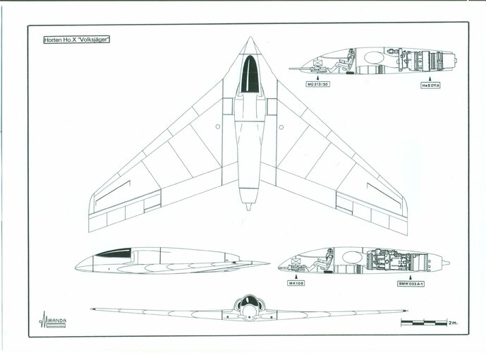
brute force solutions, the Horten thought that a small airplane, aerodynamically perfect, propelled by a single turbojet of 1300 kp, could be built with non-strategic materials to obtain performance data on the transonic flow during a series of flights in gentle dive. This project was also named Ho X to make the intelligence service of the Allied believe that it was the 
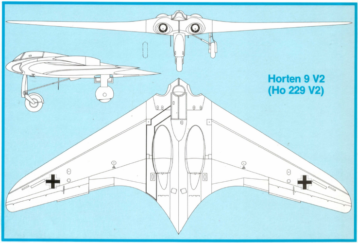
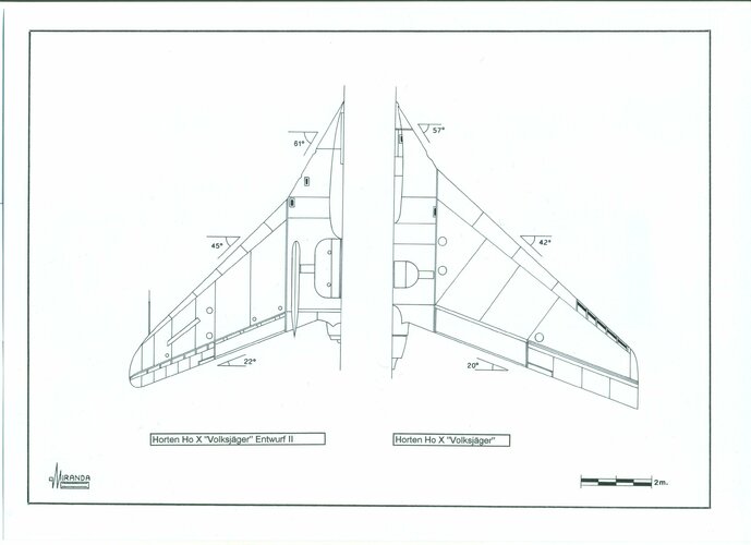
Volksjäger design. It had a 70º swept delta wing built of plywood and steel tubing with the pilot in prone position and the turbojet installed within the central section with a dorsal air-intake.


The bad transonic experience suffered on 6th of July 1944 by the Me 163 V18 prototype during a flight testing in which almost the entire rudder of the aircraft had been ripped away when reaching 702 m.p.h. suggested the Horten the possibility of avoiding the vibrations and drag produced by the tailfin, effectively removing the latest. The yaw control was obtained in the Ho X by retractable drag rods located in the wingtips.


The small airplane, with just 7.2 of span, needed to have a long runway and a great consumption of fuel to take off by its own means. Therefore, it had to be transported in Mistel configuration by a specialized airplane. The launch should be made at an altitude of 8000 m and the Ho X would then climb on its own until the 15,000 m. At that point, it started a shallow dive, progressively increasing the speed until a theoretical limit of 1195 km/h (Mach 1.07) at 6000 m


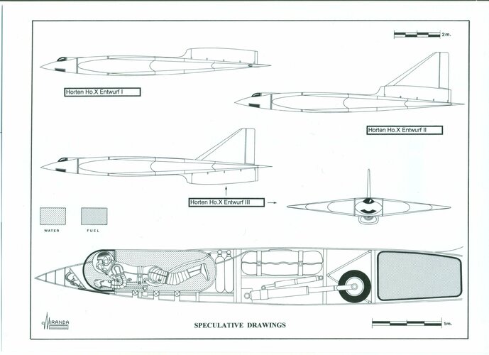
To protect the pilot from the highly destructive vibrations, expected to be encountered during the transonic phase of the flight, the Horten considered the use of a fantastic device known as Wasserkabine (water-cockpit). Although the knowledge on the Wasserkabine is almost null, it seems to have been a type of ejectable survival capsule. It was full of water during the critical phase of the flight, to protect the pilot (in prone-position and equipped with a full-pressure suit Druckanzug) from the vibrations and from the extreme physical conditions expected to exist in case of ejection at high altitude.


Supposedly, there should have been a fast disconnection system of the flying controls and no electronic equipment within the cockpit, except for the telephone wire to communicate with the launch airplane. The forward section of the Wasserkabine should allow a certain degree of visibility to see the instrument board located outside the water-cockpit and downwards. Thus the pilot could see the runway during landing with the characteristic raised AOA of the delta planes.


To prevent the discomfort and great reduction of visibility produced by the water, it is possible that the filling up of the Wasserkabine were made little before the launch either by pumping water from the mother airplane or perhaps transferring it to the Wasserkabine from some ballast tanks located in the Ho.X


An approximate estimation of the weight of the water would be around 400 kg which accumulating in the forward part of the airplane would make it a bit heavy on the nose. This feature might be useful during dive flight but would make things very difficult at landing. It seems reasonable to think that the water was pumped outside to improve the exterior visibility and reduce weight before landing. A similar procedure was used to drop the water ballast during the test flights of the Reichenberg, the piloted version of the V-1.


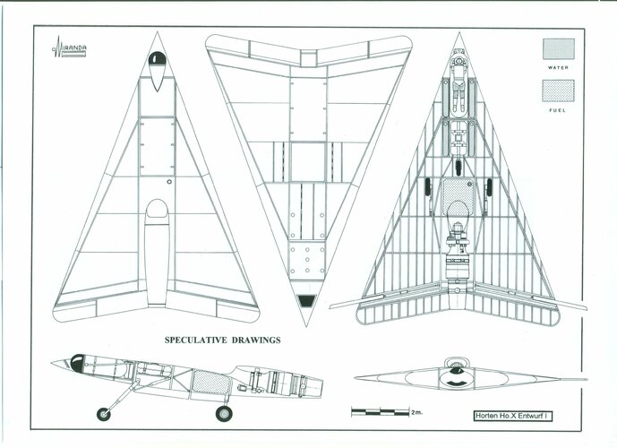
Some speculative drawings, showing the possible organization within the Ho.X, state only the opinion of the author. The Ho.X project started with a series of test flights made of balsa wood scale models in Hornberg and Göttingen. Afterwards, the construction of a wooden glider (1/1 scale) was started to investigate the subsonic handling and landing problems, although the work was not yet finished by the end of the war in Europe.


The plan was to install a conventional Argus engine pusher to make dive flying tests until reaching a maximum speed of 500 km/h. The next phase of the project would have consisted of building the prototype (Ho.X Entwurf I) equipped with a He S 011 turbojet and 
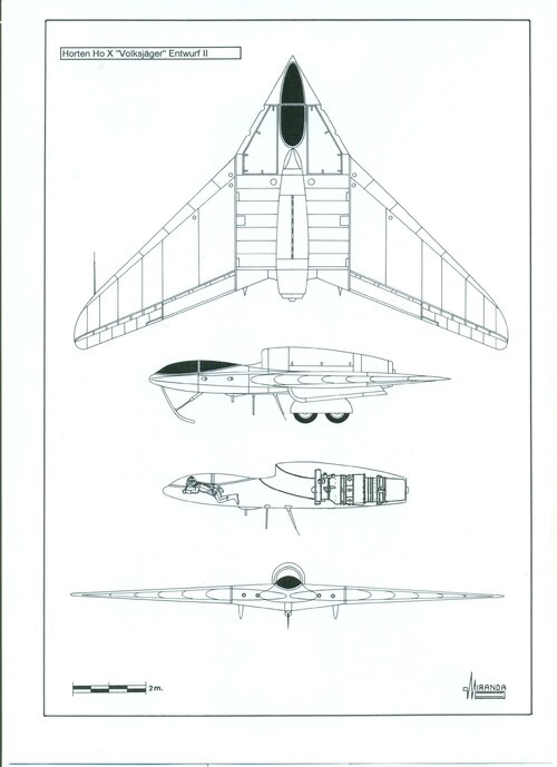
Wasserkabine for the transonic flight testing. Prior studies made with the control system proved that the drag rods could not be extended and retracted fast enough during flight at high speed.


The Entwurf II variant, with a tailfin located over the turbojet, was then designed. The aerodynamic tests made in wind tunnel proved that the engine had many possibilities to stop during landing at high AOA as the air intake stayed within the aerodynamic shadow produced by the nose.


The Entwurf III configuration appeared at this point with tailfin and the air intake in ventral position. Such precautions proved to be unfounded when a very similar British airplane named Handley Page H.P. 115 flew in 1961 equipped with a dorsal air intake without any stops of the engine.


The book 
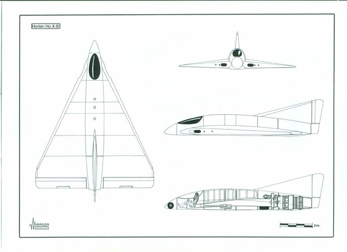
The Horten Brothers by Dr. David Myhra, published in 1998, revealed among other unknown projects, the existence of the Horten Ho X-B, a project on which only two pictures of a 1/72 scale model have been published. It seems to be a combat version of the Ho-X, somehow slower and more maneuverable with 60º delta wing and a strahlruder in the exhaust nozzle. Some scale drawings based in the pictures, rebuilding the inside in a speculative way, are based on the author personal experience and on the known data of other similar designs.


The book 
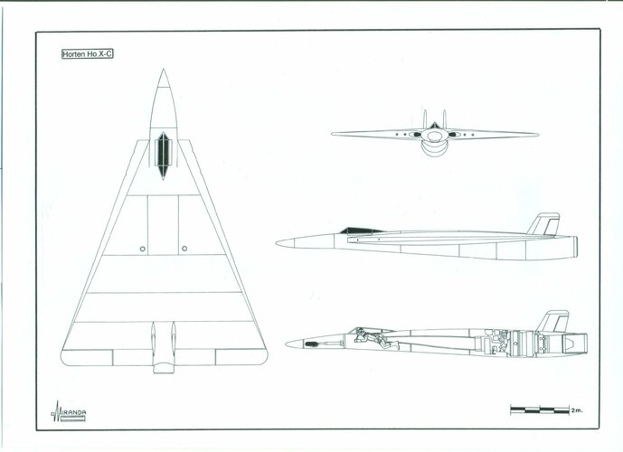
Jet Planes of the Third Reich, the Secret Projects by the German historian Manfred Griehl was also published in 1998, including a three view drawing of an airplane named Horten Ho 13-C. In the author opinion, it is a third supersonic version of the Ho X with reheated HeS 011 B engine and expansive conical nozzle.


According to the hypothetical reconstruction of the inside that we show in our drawings, it is possible that the pilot would not be in prone position but in a semi-prone "praying mantis" position, more fitted for air combat and that had been already used in the Ho IV seaplane. It is probably more accurate to name this project as Ho X-C as it clearly is derived from the Ho X without any structural relationship with the swept winged Ho XIII interceptor.


Technical data Volksjäger I​


Engine Type BMW 003 E

Engine Power 900 kp

Usage Fighter

Stage Model

Structure steel & wood

Wingspan 14 m

Length 7.2 m

Height 2.3 m

Pilot seated

Wing Area 35 sqm

Sweep 43º / 60º

Thickness -

Empty Weight -

Max Weight 6075 kg

Wing Loading 173.6 kg/sqm

Stall Speed -

Landing Speed -

Max Speed Level -

Max Speed Dive Armament 1 Mk 108/30 2x MG 131

Ceiling -

Range -


Technical data Volksjäger II​


Engine Type HeS 011

Engine Power 1300 kp

Usage fighter

Stage drawing

Structure steel & wood

Wingspan 14 m

Length 7.2 m

Height 2.3 m

Pilot seated

Wing Area 35 sqm

Sweep 43º / 60º

Thickness -

Empty Weight -

Max Weight 6000 kg

Wing Loading 171.4 kg/m2

Stall Speed -

Landing Speed 100 km/h

Max Speed Level 1100 km/h

Max Speed Dive -

Armament 1 Mk 213/30 2x MG 131

Ceiling 15000 m

Range 2000 km


Technical data Ho X Glider 1st​

Engine Type -

Engine Power -

Usage research

Stage prototype

Structure wood

Wingspan 7.2 m

Length 10 m

Height 2.38 m

Pilot prone

Wing Area 37.8 m2

Sweep 70º

Thickness 7%

Empty Weight 300 kg

Max Weight 400 kg

Wing Loading 10.5 kg/m2

Stall Speed


Technical data Ho X Glider 2nd


Engine Type As 10C

Engine Power 240 hp

Usage Research

Stage Project

Structure wood

Wingspan 7.2 m

Length 10 m

Height 2.38 m

Pilot prone

Wing Area 37.8 sqm

Sweep 70º

Thickness 7%

Empty Weight 600 kg

Max Weight 700 kg

Wing Loading 18.5 kg/sqm

Stall Speed 56 km/h

Landing Speed 88 km/h

Max Speed Level -

Max Speed Dive 500 km/h

Armament none

Ceiling -

Range -


Technical data Ho X – A​


Engine Type HeS 011

Engine Power 1300 kp

Usage research

Stage project

Structure steel & wood

Wingspan 7.2m

Length 10 m

Height 2.38 m

Pilot prone

Wing Area 37.8 sqm

Sweep 70º

Thickness 7%

Empty Weight -

Max Weight 7000 kg

Wing Loading 185 kg/sqm

Stall Speed -

Landing Speed -

Max Speed Level 1000 km/h

Max Speed Dive 1200 km/h

Armament none

Ceiling 15000 m

Range 2000 km


Technical data Ho X – B (probable)​


Engine Type HeS 011

Engine Power 1300 kp

Usage fighter

Stage project

Structure steel & wood

Wingspan 7.2 m

Length 9.8 m

Height -

Pilot seated

Wing Area -

Sweep 65º

Thickness -

Empty Weight -

Max Weight -

Wing Loading -

Stall Speed -

Landing Speed -

Max Speed Level -

Max Speed Dive -

Armament 4 x Mk 213/30

Ceiling -

Range


Technical data Ho X – C (probable)​


Engine Type HeS 011B

Engine Power 1500 kp

Usage fighter

Stage project

Structure steel & wood

Wingspan 7.2 m

Length 12 m

Height 2.25 m

Pilot semi prone

Wing Area 37.8 sqm

Sweep 70º

Thickness 7%

Empty Weight -

Max Weight -

Wing Loading -

Stall Speed -

Landing Speed -

Max Speed Level -

Max Speed Dive -

Armament 4 x Mk 213/30

Ceiling -

Range -
 

Attachments

  • Flying Wings 068.jpg
    Flying Wings 068.jpg
    466.4 KB · Views: 57
  • Flying Wings 069.jpg
    Flying Wings 069.jpg
    405.8 KB · Views: 58
  • Flying Wings 070.jpg
    Flying Wings 070.jpg
    370.6 KB · Views: 59
  • Flying Wings 071.jpg
    Flying Wings 071.jpg
    692.4 KB · Views: 61
  • Flying Wings 072.jpg
    Flying Wings 072.jpg
    623.8 KB · Views: 65
  • Flying Wings 073.jpg
    Flying Wings 073.jpg
    387.1 KB · Views: 63
  • Flying Wings 074.jpg
    Flying Wings 074.jpg
    351.9 KB · Views: 63
My take on the so called stealthy aspects are that they are limited to being 'reduced in cross section' to radar and due to the speed advantage over other designs, give a reduced warning for interception.

Stealth is not as new as we like to believe, several WW1 designs had clear skins to reduce their vulnerability to observation. The longer it takes your enemy to see you, the greater chance you will kill them first.

I just wish I could find the bleeping picture on my HDD.
The cellophane-type covering tried in WW1 turned out to be anti-stealth, because it was highly reflective.
 
I've managed to resolve the issue of the Hortens and radar stealth, based on primary source documents. I got to the bottom of it about two years ago but I've not yet found a suitable avenue for publishing my research. I did offer it to Aeroplane magazine as an article but they didn't seem interested. Long story short, the Hortens were actually telling... a version of the truth when they made their claims in interview with David Myhra.

The Horten X... don't forget that the Hortens, in Germany, were working for the British at that point. There's no evidence I'm aware of that that particular Horten X, with the prone pilot, was actually a wartime design.
 
Last edited:

Similar threads

Please donate to support the forum.

Back
Top Bottom