
You are using an out of date browser. It may not display this or other websites correctly.
You should upgrade or use an alternative browser.
You should upgrade or use an alternative browser.
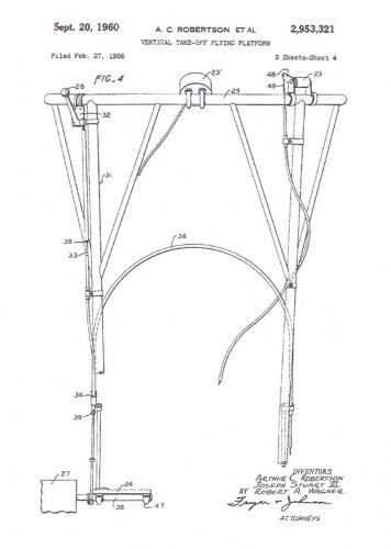
Hiller's VZ-1E « Pawnee » and other ducted-fan flying platforms
- Thread starter Barrington Bond
- Start date
- Joined
- 18 March 2008
- Messages
- 3,529
- Reaction score
- 1,172
The following is an extract from “Vertical Challenge: The Hiller Aircraft Story” by Jay P. Spencer. This book is available via 1st Books Library (www.1stbooks.com). The extract is posted here for educational purposes:
Hiller Flying Platforms
The final decade of the Hiller company’s existence - from the mid 1950s through the mid 1960s - saw continuing growth, profitability, and above all creativity. Flying Platforms and the world’s first transport-size VTOL aircraft took to the air, and countless other imaginative approaches to flight - many the product of Hiller’s new Advanced Research Division (ARD) - were thoroughly investigated. Although the majority of the ARD’s fascinating proposals would not be realized for want of military funding, the company's horizons nevertheless broadened until success seemed at last at hand on many fronts.
During this period, Hiller Helicopters would focus its energies on helicopter production, ducted-fan research, and higher-speed VTOL flight. Research-and-development itself would be a major company product; in 1957 alone, for example, the ARD would perform highly classified work for no less than five branches of the Navy, two of the Air Force, and six of Hiller’s best customer, the U.S. Army. In fact, so much non-helicopter work was going on in Palo Alto that on 10 July 1958, the company would formally change its name back to the Hiller Aircraft Corporation.
The conceptual groundwork for virtually all the “new” developments in this period had actually been laid between 1946 and 1951, primarily in the magic year 1947 when the company conducted seminal vertical-takeoff (VTO) studies using powered models. The four-engine XC-142 VTOL transport of the early 1960s dates directly back to that year, as does the wondrous Flying Platform, which is in many ways a modern flying carpet.
At the end of 1947, Hiller took advantage of a trip East to track down aeronautical engineer Charles H. Zimmerman. A longtime NACA engineer, Zimmerman’s aggressive pursuit of short-takeoff-and-landing (STOL) capability for aircraft led him to a novel circular-planform approach to aircraft design. The unconventional configuration was promising enough that in 1937 Zimmerman moved to the Chance Vought Aircraft Company in Bridgeport, Connecticut, to direct that company’s development of his idea into the experimental V-173 Flying Flapjack and its successor, the Navy’s unflown XF5U-1 fighter prototype.
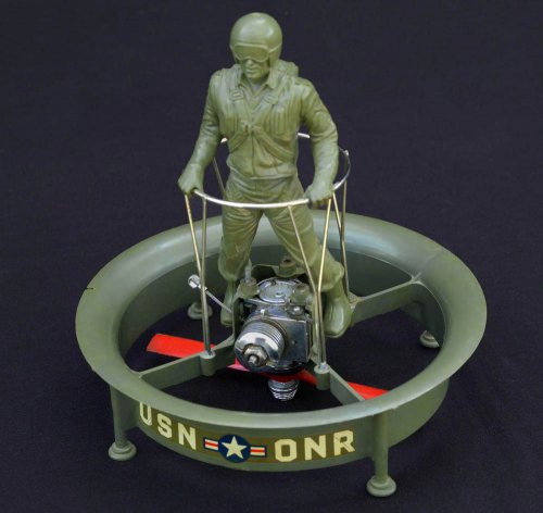
On his own, Charles Zimmerman chose to pursue with equal energy his dream of low-cost flight for humanity. At the close of World War II, this quest led him to develop a VTO test rig called the Zimmerman “Flying Shoes.” The device consisted of a small platform of light steel tubing with two small two-cycle four-cylinder target drone engines powering upward-facing propellers. After starting the Flying Shoes, a "pilot" would buckle into its metal bindings and rev up the engines with twist-grip throttles mounted on a long pole connected to the platform by a universal joint (the latter to prevent the pole from tilting the craft like a long ]ever). Once off the ground, the pilot could fly in any direction merely by shifting his weight - leaning forward to go straight ahead, leaning to the left to go that way, and so on.
http://i76.photobucket.com/albums/j35/abegubler/Zimmerman_Flying_Shoes.jpg
Invented by aeronautical engineer Charles H. Zimmerman at the close of World War II, the “Flying Shoes” platform was powered by small engines. Evaluated in Palo Alto in 1948, it was flown by shifting one’s weight toward the direction chosen, a system termed “kinesthetic control.”
Always looking for individuals with new ideas, and intrigued with the Flying Shoes concept, which paralleled ideas of his own, Stanley Hiller gave high priority to visiting Charles Zimmerman at his home in Connecticut. Impressed with the device he saw stored in the engineer’s garage, Hiller arranged to have it shipped out to California for evaluation by his company.
The Flying Shoes arrived in Palo Alto early in 1948, where long skids and tether cables were promptly attached for safety. Flown by Frank Peterson, the rig showed promise but was not raised very far off the ground because, lacking an interconnect between the engines, it was difficult to balance the thrust of the power plants. The independently powered propellers also presented the potential for a dangerous accident were one engine to fail.
Zimmerman’s Flying Shoes were based on his insight that a neutrally stable platform would result from placing the center of gravity above the plane of lift; if helicopters with rotors on top are inherently unstable, the reverse is true for flying machines with rotors mounted underneath. That the concept was not intuitively obvious to others became clear to Zimmerman when he first described his work to colleagues. “A number of my friends, all competent engineers,” he recalled with some amusement, “laughed at the idea when I mentioned it.”
Zimmerman carried his thinking one critical step further: With the plane of lift below the center of gravity, he theorized, a person’s instinctual balancing reflexes would suffice to control a vehicle, provided it was small enough. If one could walk or ride a bicycle, one could fly by what the inventor termed “kinesthetic control.”
Charles Zimmerman returned to the NACA in 1948 as assistant chief of the Stability Research Division at Wallops Island, Langley, Virginia. There he built a “Jet Board,” powered by wind tunnel air-storage spheres, upon which in February 1951 he dramatically proved a person can balance atop a jet of air. (On his first flight, in fact, the inventor failed to realize he was airborne, because controlling the platform by unconscious body motion came naturally.) Zimmerman’s follow-on propeller-driven “Whirligig” of 1953 - also powered by compressed air - further validated the startlingly simple concept of kinesthetic control.
The success of these efforts in Virginia prompted the Office of Naval Research to suggest that Hiller’s company (which had shelved the Flying Shoes in 1948 to get the UH-12-360 into production) might again pursue Zimmerman’s concepts, this time mated to the ducted-fan concept of Alexander Satin, chief engineer of the Air Branch in the ONR’s Naval Sciences Division. Intrigued with the idea, Hiller agreed, and a contract was signed on 17 September 1953.
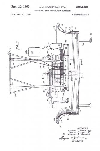
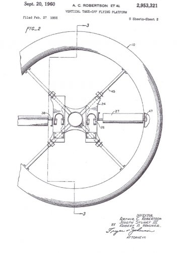
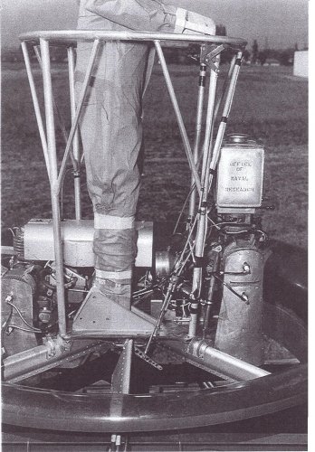
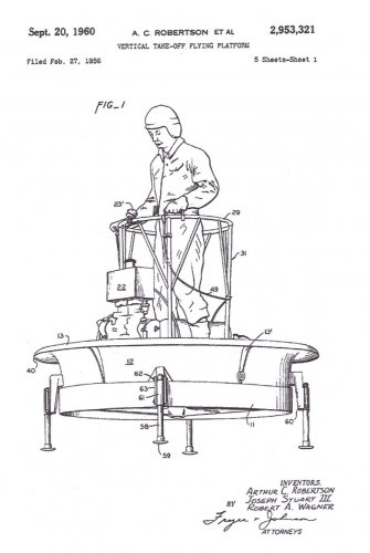
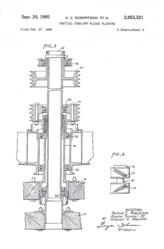
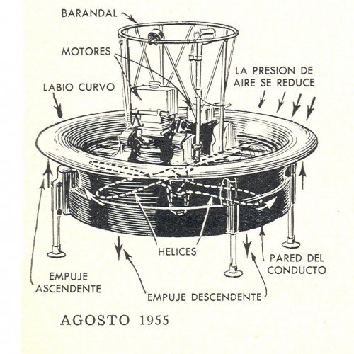
An engineering team headed by project engineer Arthur Robertson at Palo Alto set about building upon Zimmerman’s pioneering research. Working in isolation on the Model 1031, as the classified project was called, they designed a compact twin-engine platform with coaxial counter-rotating propellers encased in a fibreglass ring of airfoil cross-section. In fact, marrying Zimmerman’s ideas to Satin’s ducted fan produced a machine of surprising efficiency: the propellers produced 60 percent of the lift and the duct produced the remaining 40 percent.
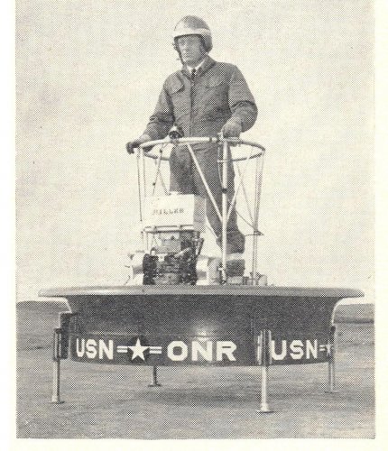
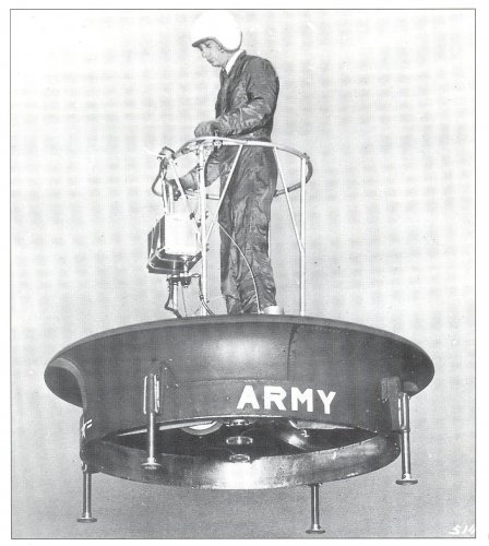
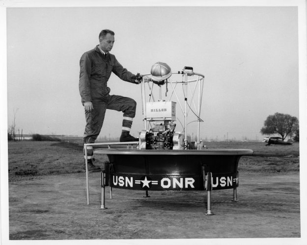
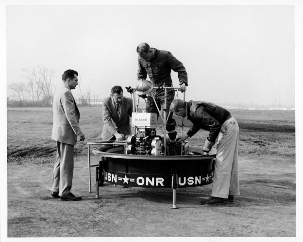
Construction of Hiller Flying Platform Number One began in January 1954 and ended nine months later, with the work proceeding slowly because only fifteen of some nine hundred Hiller employees even knew the classified craft existed. The dark-blue wingless aircraft was five feet in diameter and was light enough to be carried by two men. It was the world’s first ducted-fan VTO vehicle to fly successfully, and the first heavier-than-air aircraft capable of being flown from the outset by someone without flight training.
After unmanned evaluation of a fully instrumented duct to determine its airflow characteristics both in and out of ground effect, the three-phase test program moved on to manned testing of the first Flying Platform. Flying Shoes expert Frank Peterson had recently left the company, so Hiller chief test pilot Philip T. Johnston was assigned to the program. This capable World War II veteran ironically found himself flying a craft requiring absolutely none of the considerable piloting skills he had honed during eighty fighter sweeps over Europe.
Johnston gingerly explored the platform’s kinesthetic controllability in a “high-wire” tether arrangement which permitted limited vertical and horizontal flight. The unique vehicle demonstrated unusual but acceptable flight characteristics, so after several weeks the team moved on to the third - and most dramatic - phase of testing.
Hiller’s Flying Platform made its first free flight on 27 January 1955. Unfettered, it flew with far greater precision and control authority than its size might have suggested. And it was quick, heeling into tight turns as it zipped smartly through maneuvers. In horizontal flight, however, speed was inherently restricted owing to an uneven distribution of induced flow across the duct (and, to a lesser degree, because of airflow interference by the pilot and the framework on which he stood). The result was that greater lift was developed by the front of the Flying Platform than the rear. When the pilot leaned to tilt the craft in the direction he desired to go, therefore, it “pushed backs” enough to retard its speed. Since it still whisked along much faster than a man could run, however, and as this “limitation” added to the vehicle's safety, its developers were well satisfied.
After three months, all secrecy was dropped and the Flying Platform made its debut to surprisingly wide acclaim. A public accustomed to unusual doings at Hiller now had more grist for daydreams images of privately owned Flying Platforms once again rekindled dreams of low-cost personal flying machines.
The 29 April 1955 issue of Collier’s magazine featured Hiller’s blue prototype in flight on its cover. “As we watched,” the article’s authors reported, “Hiller test pilot Phil T. Johnston, hovering several feet in the air, moved a small ring-shaped platform forward and back and from side to side. There was no visible evidence of what was keeping Johnston in the air. Only the staccato bark of engines indicated that here was no form of magic, but a new and revolutionary flying device, forerunner of a possible series of exciting air vehicles unlike anything that has flown before.”
The article suggests the particular delight evoked by the imaginative new aircraft: “Because Hiller’s flying platform bears such a marked resemblance to the flying saucers that have so captured public fancy, even an expert's first reaction as it rises from the ground is likely to be a mixture of sheer amazement and the urge to chuckle at so comic a concept.”
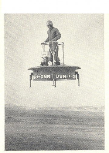
http://i76.photobucket.com/albums/j35/abegubler/Hiller_Flying_Platform.jpg
Developed as a classified project for the Office of Naval Research, the Hiller Flying Platform combined intuitive control with a ducted fan for high efficiency and a small diameter. The tether cables shown here facilitate early tests and training.
Work was already under way on a second - and safer - unit. The original Flying Platform had each propeller directly driven with no interconnect, a very dangerous situation in the event of an engine failure; such an occurrence at altitude would cause the vehicle to spin out of control, probably with fatal consequences. Succeeding platforms, therefore, would all have a revised drive system linking both propellers through a gearbox so that each engine powered both propellers. Thus deprived of differential throttling for yaw control, these platforms would need underside control vanes to rotate about the vertical axis.
With a life-size weighted dummy at its controls to maintain its center of gravity, the first prototype was mounted in a tiltable frame atop a Hiller pickup truck that raced up and down Moffett Field’s long runways. Lacking a wind tunnel, Hiller often availed itself of the Navy base in this manner to obtain low-speed aerodynamic data. The purpose of this particular series of tests was to investigate the transition of ducted fans to horizontal flight, as might be required of VTOL aircraft in the future. Hiller, in fact, was already thinking of futuristic high-performance ducted-fan derivatives.
Two further ducted-fan study contracts were received from the research-oriented ONR. The first was for a rectangular and rather flat giant crane built around four huge ducts with counter-rotating fans. The second was for a crane with side-mounted tilting ducts. Neither of these ideas progressed beyond the conceptual stage.
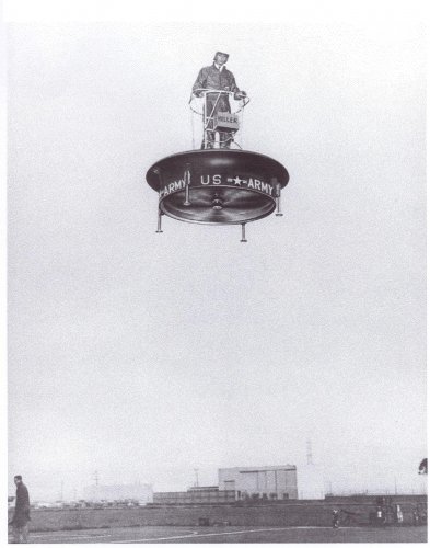
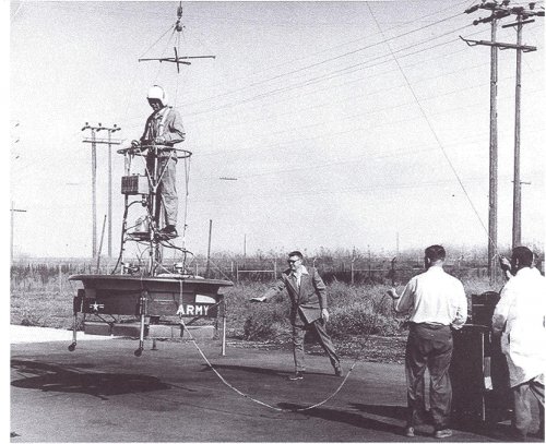
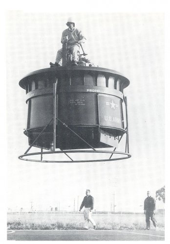
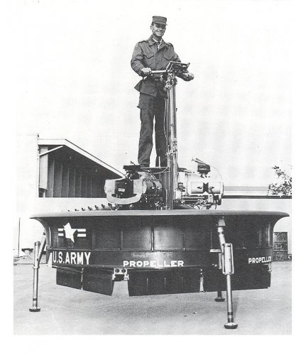
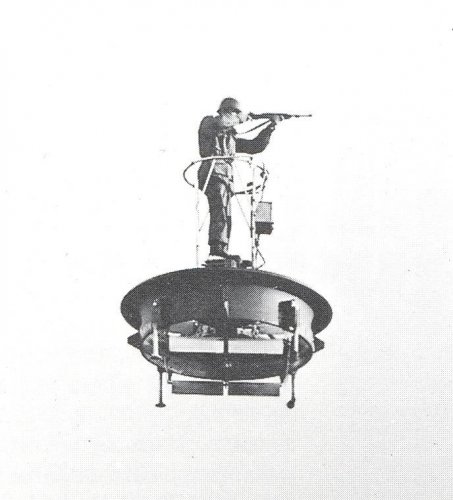
At this juncture, the U.S. Army took over responsibility for funding further developments of the Hiller Flying Platform. But blinded by visions of flying carpets for infantrymen, Army officials failed to appreciate the potential of more exotic ducted-fan vehicles. They wanted simply to enlarge the basic platform for use as a reconnaissance vehicle or for crossing mine fields and other man-made or natural barriers. They also foresaw it as an elevated firing platform for infantry sharpshooters. Accordingly, the Army issued a contract in 1956 for three Hiller YHO-1Bs, or VZ-1s as they were soon rechristened (the new designation denoting research-vehicle status). Later amended to two VZ-1Es (a third was retained by the company), this contract was fulfilled in December 1957 and testing began the following year.
For safety, a third engine was added to permit continued flight even if one engine were to fail. This well-intended safety measure, along with the wider six-foot-diameter duct it necessitated, made these new Flying Platforms so cumbersome that they no longer responded effectively to kinesthetic control. With proportionately less “crew” weight to control it, they were also appreciably less stable. Following unsuccessful efforts to develop aerodynamic control augmentation devices - evaluated by both Hiller and Army pilots - the unwieldy VZ-1Es were soon retired. With the Flying Platform now too big and too unwieldy to be useful to the infantry, the Army lost interest. Hiller’s promising kinesthetic-control ducted-fan program came to an abrupt end.
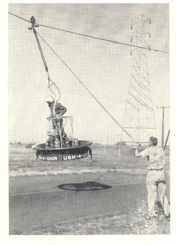
http://i76.photobucket.com/albums/j35/abegubler/Hiller_VZ-1E-1.jpg
Army specification of three engines (for safety, should any one engine fail) produced Flying Platforms too heavy to respond well to kinesthetic control. Courtesy NASM/SI
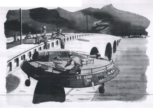
Disappointed with the Army’s waning interest, the Hiller team sought to salvage whatever support might remain by submitting proposals for logical Flying Platform developments. The first of these was a flying Jeep with four ducted fans, two at the front and two at the rear. Illustrations of the Hiller Flying Jeep showed an olive-drab vehicle with open seating. It somewhat suggested its ground-based inspiration, although it was a much more substantial vehicle. Powered either by a T58 or two T63 turbine engines, in fact, the craft as proposed by Hiller could lift a standard Army truck. The Hiller Flying Jeep was eminently feasible, as it built directly upon work already accomplished.
Although Hiller alone had the experience to build such a craft, the Army - which was required to solicit competitive bids from industry - awarded aerial jeep contracts to Piasecki; the Aerophysics Development Corporation of Santa Barbara, California (a division of Curtiss-Wright); and Chrysler. None of these manufacturers had much if any experience with ducted fans, and Chrysler had never even built an aircraft! When these contractors failed to produce a viable aerial jeep, the Army cancelled the program. For Hiller, it was another frustrating lesson in the arcane workings of procurement.
“We should have spent more of the cost of a proposal on a mock-up,” Hiller reflected in later years, observing that a full-size model of the Flying Jeep might well have tipped the scales in its favor. Had there been a “showroom display” model for Army generals to inspect and sit in, American ground forces might well have had Flying Jeeps in their inventory.
http://i76.photobucket.com/albums/j35/abegubler/Hiller_Flying_Jeep.jpg
Proposed in the late 1950s, the Hiller Flying Jeep had a ducted fan at each corner. After soliciting industry wide bids for such a vehicle, the Army issued ssited Contracts to manufacturers who, lacking Hiller’s ducted fan expertise, were unable to produce successful vehicles.
A second and more exotic Flying Platform derivative was the proposed Ring-Wing Coleopter, a high-speed aircraft that could take off vertically, fly horizontally using its ducted fan as a circular wing, then land vertically again. Moffett Field tests of Flying Platform Number One, described above, generated data for this project, as did the third VZ-1, which was retained by Hiller as an aerodynamic testbed. High-speed ducted-fan flight research was also sponsored by the Navy, which awarded Hiller a contract to study “ring-wing” horizontal flight.
Phil Johnston actually flew the first-generation Coleopter, evaluating both its aerodynamic controls and its extended duct configuration. Before a true prototype could be built and a full conversion attempted, however, the Army - which sponsored construction of the prototype - cancelled the project.
http://i76.photobucket.com/albums/j35/abegubler/Hiller_Ring-Wing_Coleopter.jpg
The two Hiller VZ-lEs of 1957 were prototypes of the proposed Hiller Ring-Wing Coleopter, a craft capable of high-speed horizontal flight.
Seven Hiller Flying Platforms in all are believed to have been built. Retired after several years of use, the historic first example in dark-blue ONR paint is now on display at the Hiller Aviation Museum In San Carlos, California, one of the nation’s top flight museums. A second twin-engine Platform in Army colors is on display at the Paul E. Garber Facility in Silver Hill, Maryland, where much of the collection of the Smithsonian Institution’s National Air and Space Museum is housed. The VZ-lEs were last reported to be at Princeton University for ducted-fan research at that institution.
Hiller Flying Platforms
The final decade of the Hiller company’s existence - from the mid 1950s through the mid 1960s - saw continuing growth, profitability, and above all creativity. Flying Platforms and the world’s first transport-size VTOL aircraft took to the air, and countless other imaginative approaches to flight - many the product of Hiller’s new Advanced Research Division (ARD) - were thoroughly investigated. Although the majority of the ARD’s fascinating proposals would not be realized for want of military funding, the company's horizons nevertheless broadened until success seemed at last at hand on many fronts.
During this period, Hiller Helicopters would focus its energies on helicopter production, ducted-fan research, and higher-speed VTOL flight. Research-and-development itself would be a major company product; in 1957 alone, for example, the ARD would perform highly classified work for no less than five branches of the Navy, two of the Air Force, and six of Hiller’s best customer, the U.S. Army. In fact, so much non-helicopter work was going on in Palo Alto that on 10 July 1958, the company would formally change its name back to the Hiller Aircraft Corporation.
The conceptual groundwork for virtually all the “new” developments in this period had actually been laid between 1946 and 1951, primarily in the magic year 1947 when the company conducted seminal vertical-takeoff (VTO) studies using powered models. The four-engine XC-142 VTOL transport of the early 1960s dates directly back to that year, as does the wondrous Flying Platform, which is in many ways a modern flying carpet.
At the end of 1947, Hiller took advantage of a trip East to track down aeronautical engineer Charles H. Zimmerman. A longtime NACA engineer, Zimmerman’s aggressive pursuit of short-takeoff-and-landing (STOL) capability for aircraft led him to a novel circular-planform approach to aircraft design. The unconventional configuration was promising enough that in 1937 Zimmerman moved to the Chance Vought Aircraft Company in Bridgeport, Connecticut, to direct that company’s development of his idea into the experimental V-173 Flying Flapjack and its successor, the Navy’s unflown XF5U-1 fighter prototype.
On his own, Charles Zimmerman chose to pursue with equal energy his dream of low-cost flight for humanity. At the close of World War II, this quest led him to develop a VTO test rig called the Zimmerman “Flying Shoes.” The device consisted of a small platform of light steel tubing with two small two-cycle four-cylinder target drone engines powering upward-facing propellers. After starting the Flying Shoes, a "pilot" would buckle into its metal bindings and rev up the engines with twist-grip throttles mounted on a long pole connected to the platform by a universal joint (the latter to prevent the pole from tilting the craft like a long ]ever). Once off the ground, the pilot could fly in any direction merely by shifting his weight - leaning forward to go straight ahead, leaning to the left to go that way, and so on.
http://i76.photobucket.com/albums/j35/abegubler/Zimmerman_Flying_Shoes.jpg
Invented by aeronautical engineer Charles H. Zimmerman at the close of World War II, the “Flying Shoes” platform was powered by small engines. Evaluated in Palo Alto in 1948, it was flown by shifting one’s weight toward the direction chosen, a system termed “kinesthetic control.”
Always looking for individuals with new ideas, and intrigued with the Flying Shoes concept, which paralleled ideas of his own, Stanley Hiller gave high priority to visiting Charles Zimmerman at his home in Connecticut. Impressed with the device he saw stored in the engineer’s garage, Hiller arranged to have it shipped out to California for evaluation by his company.
The Flying Shoes arrived in Palo Alto early in 1948, where long skids and tether cables were promptly attached for safety. Flown by Frank Peterson, the rig showed promise but was not raised very far off the ground because, lacking an interconnect between the engines, it was difficult to balance the thrust of the power plants. The independently powered propellers also presented the potential for a dangerous accident were one engine to fail.
Zimmerman’s Flying Shoes were based on his insight that a neutrally stable platform would result from placing the center of gravity above the plane of lift; if helicopters with rotors on top are inherently unstable, the reverse is true for flying machines with rotors mounted underneath. That the concept was not intuitively obvious to others became clear to Zimmerman when he first described his work to colleagues. “A number of my friends, all competent engineers,” he recalled with some amusement, “laughed at the idea when I mentioned it.”
Zimmerman carried his thinking one critical step further: With the plane of lift below the center of gravity, he theorized, a person’s instinctual balancing reflexes would suffice to control a vehicle, provided it was small enough. If one could walk or ride a bicycle, one could fly by what the inventor termed “kinesthetic control.”
Charles Zimmerman returned to the NACA in 1948 as assistant chief of the Stability Research Division at Wallops Island, Langley, Virginia. There he built a “Jet Board,” powered by wind tunnel air-storage spheres, upon which in February 1951 he dramatically proved a person can balance atop a jet of air. (On his first flight, in fact, the inventor failed to realize he was airborne, because controlling the platform by unconscious body motion came naturally.) Zimmerman’s follow-on propeller-driven “Whirligig” of 1953 - also powered by compressed air - further validated the startlingly simple concept of kinesthetic control.
The success of these efforts in Virginia prompted the Office of Naval Research to suggest that Hiller’s company (which had shelved the Flying Shoes in 1948 to get the UH-12-360 into production) might again pursue Zimmerman’s concepts, this time mated to the ducted-fan concept of Alexander Satin, chief engineer of the Air Branch in the ONR’s Naval Sciences Division. Intrigued with the idea, Hiller agreed, and a contract was signed on 17 September 1953.
An engineering team headed by project engineer Arthur Robertson at Palo Alto set about building upon Zimmerman’s pioneering research. Working in isolation on the Model 1031, as the classified project was called, they designed a compact twin-engine platform with coaxial counter-rotating propellers encased in a fibreglass ring of airfoil cross-section. In fact, marrying Zimmerman’s ideas to Satin’s ducted fan produced a machine of surprising efficiency: the propellers produced 60 percent of the lift and the duct produced the remaining 40 percent.
Construction of Hiller Flying Platform Number One began in January 1954 and ended nine months later, with the work proceeding slowly because only fifteen of some nine hundred Hiller employees even knew the classified craft existed. The dark-blue wingless aircraft was five feet in diameter and was light enough to be carried by two men. It was the world’s first ducted-fan VTO vehicle to fly successfully, and the first heavier-than-air aircraft capable of being flown from the outset by someone without flight training.
After unmanned evaluation of a fully instrumented duct to determine its airflow characteristics both in and out of ground effect, the three-phase test program moved on to manned testing of the first Flying Platform. Flying Shoes expert Frank Peterson had recently left the company, so Hiller chief test pilot Philip T. Johnston was assigned to the program. This capable World War II veteran ironically found himself flying a craft requiring absolutely none of the considerable piloting skills he had honed during eighty fighter sweeps over Europe.
Johnston gingerly explored the platform’s kinesthetic controllability in a “high-wire” tether arrangement which permitted limited vertical and horizontal flight. The unique vehicle demonstrated unusual but acceptable flight characteristics, so after several weeks the team moved on to the third - and most dramatic - phase of testing.
Hiller’s Flying Platform made its first free flight on 27 January 1955. Unfettered, it flew with far greater precision and control authority than its size might have suggested. And it was quick, heeling into tight turns as it zipped smartly through maneuvers. In horizontal flight, however, speed was inherently restricted owing to an uneven distribution of induced flow across the duct (and, to a lesser degree, because of airflow interference by the pilot and the framework on which he stood). The result was that greater lift was developed by the front of the Flying Platform than the rear. When the pilot leaned to tilt the craft in the direction he desired to go, therefore, it “pushed backs” enough to retard its speed. Since it still whisked along much faster than a man could run, however, and as this “limitation” added to the vehicle's safety, its developers were well satisfied.
After three months, all secrecy was dropped and the Flying Platform made its debut to surprisingly wide acclaim. A public accustomed to unusual doings at Hiller now had more grist for daydreams images of privately owned Flying Platforms once again rekindled dreams of low-cost personal flying machines.
The 29 April 1955 issue of Collier’s magazine featured Hiller’s blue prototype in flight on its cover. “As we watched,” the article’s authors reported, “Hiller test pilot Phil T. Johnston, hovering several feet in the air, moved a small ring-shaped platform forward and back and from side to side. There was no visible evidence of what was keeping Johnston in the air. Only the staccato bark of engines indicated that here was no form of magic, but a new and revolutionary flying device, forerunner of a possible series of exciting air vehicles unlike anything that has flown before.”
The article suggests the particular delight evoked by the imaginative new aircraft: “Because Hiller’s flying platform bears such a marked resemblance to the flying saucers that have so captured public fancy, even an expert's first reaction as it rises from the ground is likely to be a mixture of sheer amazement and the urge to chuckle at so comic a concept.”
http://i76.photobucket.com/albums/j35/abegubler/Hiller_Flying_Platform.jpg
Developed as a classified project for the Office of Naval Research, the Hiller Flying Platform combined intuitive control with a ducted fan for high efficiency and a small diameter. The tether cables shown here facilitate early tests and training.
Work was already under way on a second - and safer - unit. The original Flying Platform had each propeller directly driven with no interconnect, a very dangerous situation in the event of an engine failure; such an occurrence at altitude would cause the vehicle to spin out of control, probably with fatal consequences. Succeeding platforms, therefore, would all have a revised drive system linking both propellers through a gearbox so that each engine powered both propellers. Thus deprived of differential throttling for yaw control, these platforms would need underside control vanes to rotate about the vertical axis.
With a life-size weighted dummy at its controls to maintain its center of gravity, the first prototype was mounted in a tiltable frame atop a Hiller pickup truck that raced up and down Moffett Field’s long runways. Lacking a wind tunnel, Hiller often availed itself of the Navy base in this manner to obtain low-speed aerodynamic data. The purpose of this particular series of tests was to investigate the transition of ducted fans to horizontal flight, as might be required of VTOL aircraft in the future. Hiller, in fact, was already thinking of futuristic high-performance ducted-fan derivatives.
Two further ducted-fan study contracts were received from the research-oriented ONR. The first was for a rectangular and rather flat giant crane built around four huge ducts with counter-rotating fans. The second was for a crane with side-mounted tilting ducts. Neither of these ideas progressed beyond the conceptual stage.
At this juncture, the U.S. Army took over responsibility for funding further developments of the Hiller Flying Platform. But blinded by visions of flying carpets for infantrymen, Army officials failed to appreciate the potential of more exotic ducted-fan vehicles. They wanted simply to enlarge the basic platform for use as a reconnaissance vehicle or for crossing mine fields and other man-made or natural barriers. They also foresaw it as an elevated firing platform for infantry sharpshooters. Accordingly, the Army issued a contract in 1956 for three Hiller YHO-1Bs, or VZ-1s as they were soon rechristened (the new designation denoting research-vehicle status). Later amended to two VZ-1Es (a third was retained by the company), this contract was fulfilled in December 1957 and testing began the following year.
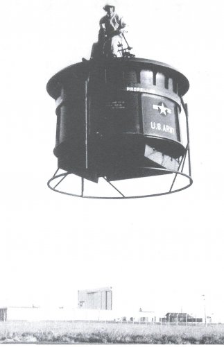
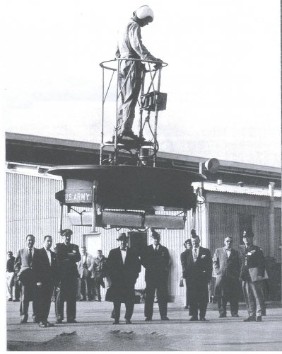
For safety, a third engine was added to permit continued flight even if one engine were to fail. This well-intended safety measure, along with the wider six-foot-diameter duct it necessitated, made these new Flying Platforms so cumbersome that they no longer responded effectively to kinesthetic control. With proportionately less “crew” weight to control it, they were also appreciably less stable. Following unsuccessful efforts to develop aerodynamic control augmentation devices - evaluated by both Hiller and Army pilots - the unwieldy VZ-1Es were soon retired. With the Flying Platform now too big and too unwieldy to be useful to the infantry, the Army lost interest. Hiller’s promising kinesthetic-control ducted-fan program came to an abrupt end.
http://i76.photobucket.com/albums/j35/abegubler/Hiller_VZ-1E-1.jpg
Army specification of three engines (for safety, should any one engine fail) produced Flying Platforms too heavy to respond well to kinesthetic control. Courtesy NASM/SI
Disappointed with the Army’s waning interest, the Hiller team sought to salvage whatever support might remain by submitting proposals for logical Flying Platform developments. The first of these was a flying Jeep with four ducted fans, two at the front and two at the rear. Illustrations of the Hiller Flying Jeep showed an olive-drab vehicle with open seating. It somewhat suggested its ground-based inspiration, although it was a much more substantial vehicle. Powered either by a T58 or two T63 turbine engines, in fact, the craft as proposed by Hiller could lift a standard Army truck. The Hiller Flying Jeep was eminently feasible, as it built directly upon work already accomplished.
Although Hiller alone had the experience to build such a craft, the Army - which was required to solicit competitive bids from industry - awarded aerial jeep contracts to Piasecki; the Aerophysics Development Corporation of Santa Barbara, California (a division of Curtiss-Wright); and Chrysler. None of these manufacturers had much if any experience with ducted fans, and Chrysler had never even built an aircraft! When these contractors failed to produce a viable aerial jeep, the Army cancelled the program. For Hiller, it was another frustrating lesson in the arcane workings of procurement.
“We should have spent more of the cost of a proposal on a mock-up,” Hiller reflected in later years, observing that a full-size model of the Flying Jeep might well have tipped the scales in its favor. Had there been a “showroom display” model for Army generals to inspect and sit in, American ground forces might well have had Flying Jeeps in their inventory.
http://i76.photobucket.com/albums/j35/abegubler/Hiller_Flying_Jeep.jpg
Proposed in the late 1950s, the Hiller Flying Jeep had a ducted fan at each corner. After soliciting industry wide bids for such a vehicle, the Army issued ssited Contracts to manufacturers who, lacking Hiller’s ducted fan expertise, were unable to produce successful vehicles.
A second and more exotic Flying Platform derivative was the proposed Ring-Wing Coleopter, a high-speed aircraft that could take off vertically, fly horizontally using its ducted fan as a circular wing, then land vertically again. Moffett Field tests of Flying Platform Number One, described above, generated data for this project, as did the third VZ-1, which was retained by Hiller as an aerodynamic testbed. High-speed ducted-fan flight research was also sponsored by the Navy, which awarded Hiller a contract to study “ring-wing” horizontal flight.
Phil Johnston actually flew the first-generation Coleopter, evaluating both its aerodynamic controls and its extended duct configuration. Before a true prototype could be built and a full conversion attempted, however, the Army - which sponsored construction of the prototype - cancelled the project.
http://i76.photobucket.com/albums/j35/abegubler/Hiller_Ring-Wing_Coleopter.jpg
The two Hiller VZ-lEs of 1957 were prototypes of the proposed Hiller Ring-Wing Coleopter, a craft capable of high-speed horizontal flight.
Seven Hiller Flying Platforms in all are believed to have been built. Retired after several years of use, the historic first example in dark-blue ONR paint is now on display at the Hiller Aviation Museum In San Carlos, California, one of the nation’s top flight museums. A second twin-engine Platform in Army colors is on display at the Paul E. Garber Facility in Silver Hill, Maryland, where much of the collection of the Smithsonian Institution’s National Air and Space Museum is housed. The VZ-lEs were last reported to be at Princeton University for ducted-fan research at that institution.
- Joined
- 17 October 2006
- Messages
- 2,396
- Reaction score
- 1,278
I'm going to jump on to a flying Cuisinart! Maybe not...
- Joined
- 25 June 2009
- Messages
- 15,517
- Reaction score
- 9,299
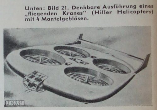
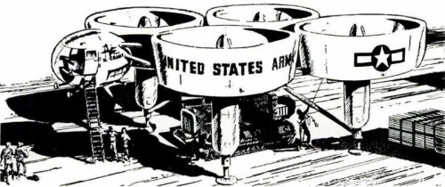
Artist's concept (top) of the Hiller "Flying Crane". The "Flying Crane" would consist of four large fans, each about 15 feet in diameter. They would be bolted together in the form of a rough square to provide great lifting capacity. The gas turbine powerplant would be located in the center, with a bubble-like control cabin placed in the front. Standing off the ground on tall, stilt-like legs. there would be plenty of room below the crane for moving into place below it a heavy tractor, large truck, or loaded cargo box. The "Flying Crane" was proposed to the US Army for lifting trucks and tractors over rough terrain.
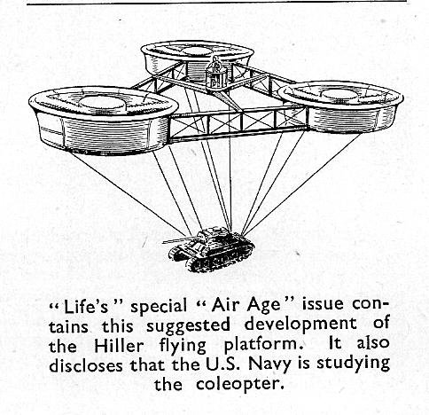
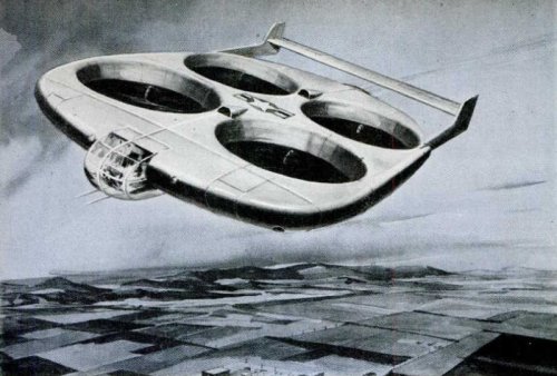
Artist's concept (bottom) of Hiller flying platform. "Four large fans in a streamlined airfoil could be combined with jet engines for swift forward propulsion."
Source: Stimson, Jr. Thomas E. "Your Aerial Sedan for 1967" Popular Mechanics July 1957 page 77.
Artist's concept (bottom) of Hiller flying platform. "Four large fans in a streamlined airfoil could be combined with jet engines for swift forward propulsion."
Source: Stimson, Jr. Thomas E. "Your Aerial Sedan for 1967" Popular Mechanics July 1957 page 77.
Attachments
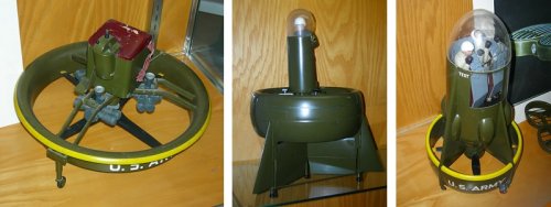
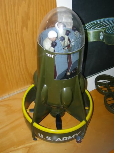
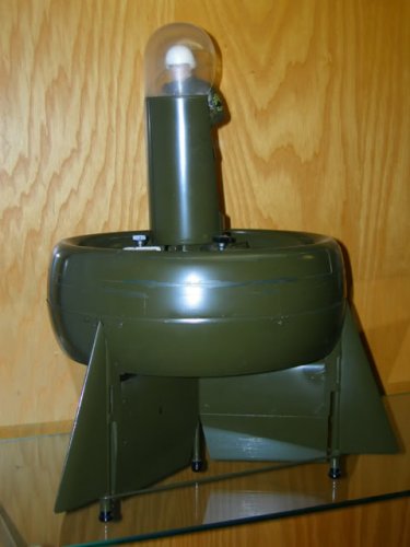
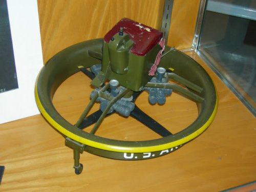
Models of Hiller VZ-1 derivatives on display at the Hiller Aviation Institute and Museum.
Source: http://www.freewebs.com/aeroscale/hillermuseum.htm
Source: http://www.freewebs.com/aeroscale/hillermuseum.htm
Attachments
- Joined
- 25 June 2009
- Messages
- 15,517
- Reaction score
- 9,299
Thanks. Some of these and more Hiller VTOL projects can be found here:
http://www.secretprojects.co.uk/forum/index.php/topic,3687.15.html
http://www.secretprojects.co.uk/forum/index.php/topic,3687.15.html
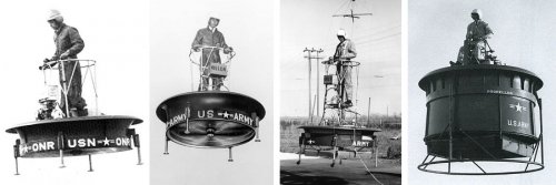
Stargazer2006 said:The evolution of Hiller's Model 1031 / VZ-1E (first set of pictures)
Projected derivatives of the VZ-1 (second set of pictures)
Hi ,
Was there a Polish idea that was some what similar pre-2ndWW?
In a book on Polish Aircraft, Putnam?
Additional Hiller stuff-POST-1
From
-Le Fanatique de l'Aviation-Février 2001
-Mecanica Popular Agosto 1955/Septiembre 1957
-Science et Vie unknown issue
From
-Le Fanatique de l'Aviation-Février 2001
-Mecanica Popular Agosto 1955/Septiembre 1957
-Science et Vie unknown issue
Attachments
Additional Hiller stuff-POST-2
From
-Le Fanatique de l'Aviation-Février 2001
-Mecanica Popular Agosto 1955/Septiembre 1957
-Science et Vie unknown issue
From
-Le Fanatique de l'Aviation-Février 2001
-Mecanica Popular Agosto 1955/Septiembre 1957
-Science et Vie unknown issue
Attachments

Additional Hiller stuff-POST-5
From
-Le Fanatique de l'Aviation-Février 2001
-Mecanica Popular Agosto 1955/Septiembre 1957
-Science et Vie unknown issue
From
-Le Fanatique de l'Aviation-Février 2001
-Mecanica Popular Agosto 1955/Septiembre 1957
-Science et Vie unknown issue
Attachments
- Joined
- 31 May 2009
- Messages
- 1,155
- Reaction score
- 793
- Joined
- 13 August 2007
- Messages
- 9,834
- Reaction score
- 16,304
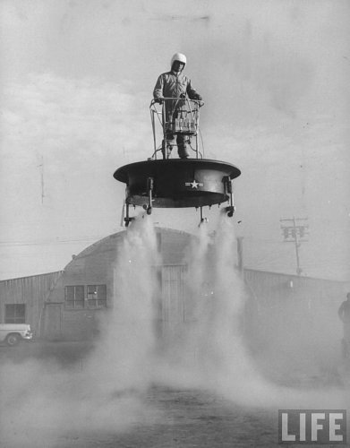
Cant find my original report on the "Experimental Investigation of Flight of a Person Supported by a Jet Thrust Device Attached to His Feet" from Zimmerman at Langley. It was on my desk a couple of weeks ago, and must be here SOMEwhere?
But it should be noted that the Jet Pad had a 1/8 hp, 8000 rpm, 15 lb gyroscope for stabilization. It was a fairly light, complete jet pad unit at under 100 lbs. There were six flight tests in February, and another 15 flight tests in November of 1951, with most of them lasting either 5 or 10 minutes, each, charted individually. There were five test pilots, who weighed between 135 and 180 lbs. The test report is filled with full page charts, photos and dwgs of the tests and the unit, with and without pilots, and various configurations, including one with a control stick, instead of leaning
But it should be noted that the Jet Pad had a 1/8 hp, 8000 rpm, 15 lb gyroscope for stabilization. It was a fairly light, complete jet pad unit at under 100 lbs. There were six flight tests in February, and another 15 flight tests in November of 1951, with most of them lasting either 5 or 10 minutes, each, charted individually. There were five test pilots, who weighed between 135 and 180 lbs. The test report is filled with full page charts, photos and dwgs of the tests and the unit, with and without pilots, and various configurations, including one with a control stick, instead of leaning
- Joined
- 25 June 2009
- Messages
- 15,517
- Reaction score
- 9,299
From a Hiller report on pulse reactors and their possible applications:
http://www.dtic.mil/cgi-bin/GetTRDoc?AD=AD0825218
http://www.dtic.mil/cgi-bin/GetTRDoc?AD=AD0825218
Attachments
Hi Justo, Do you know from which magazine exactly this image came from?Additional Hiller stuff-POST-4
From
-Le Fanatique de l'Aviation-Février 2001
-Mecanica Popular Agosto 1955/Septiembre 1957
-Science et Vie unknown issue

No
- Joined
- 13 June 2007
- Messages
- 2,220
- Reaction score
- 3,541
Similar threads
-
 Fairchild M-224-1 Fledgling (US Army VZ-5FA)
- Started by Stargazer
- Replies: 7
-
 Hiller's Flying Jeeps and Aerial Sedans
- Started by Triton
- Replies: 4
-
Hiller Model 1010 and 1011 "Captive Helicopters"
- Started by Harold Biondo
- Replies: 2
-
 Bell D181 Ducted-fan transport project
- Started by Jemiba
- Replies: 21
-
Various Bell ducted-fan VTOL projects
- Started by Jemiba
- Replies: 10