Early Soviet AI radar

yellowaster

ACCESS: Confidential
Joined
1 January 2009
Messages
132
Reaction score
155
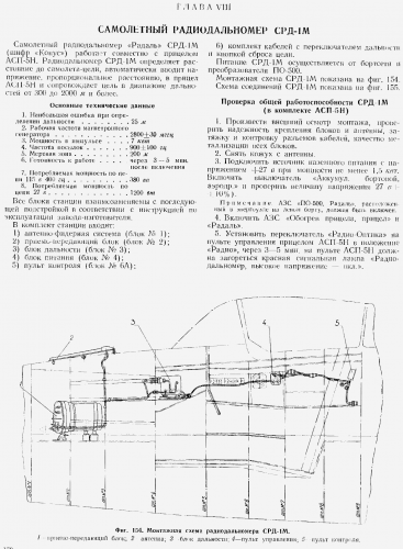
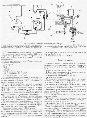
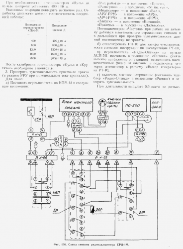
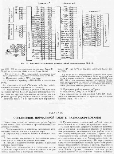
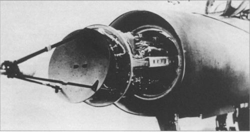
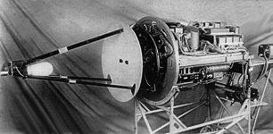
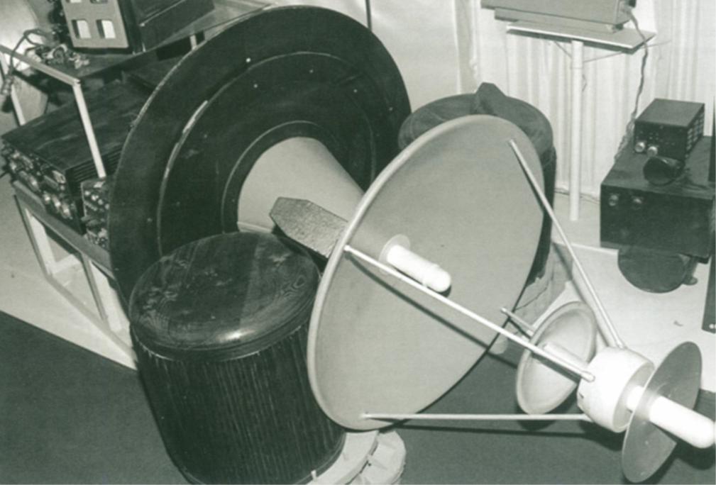
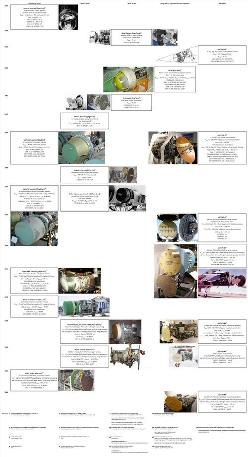
Does anyone have any information on the frequency bands used by early Soviet ranging and AI radars in use in the 1950s in the Mig-17P/F, Mig-19P/F and Yak-25 ? e.g. the RP-1, RP-2, RP-5, RP-6 and the SRD-1 and SRD-5 ? I had previously assumed they would be S-band but now I'm not so sure. Web searches produce a bit of info on the evolution of the various radars (including range etc) but nothing on the frequencies used.

thanks,

YA
 
"Scan Odd" (RP-5 Izumrud on MiG-19 was 9.3-9.4GHz, X band (I band). Western accounts in the Cold War said there were S and X band versions of Izumrud.
 
Paul,

thanks. Can you recommend any references on the subject ? I was thinking of looking at some of Air Intell summaries next time I visit the National Archives, but maybe there are published sources ?

regards,

YA
 
I haven't been researching that area much in the last 6 years or so, but the Russian language websites and publications would be the best option. Websites can be eeasily used with translation - Chrome does this by default. There are copies of flight manuals for MiG-19 etc floating around which may provide useful information.
 
Try searching on Google for the radars in Russian characters like so:

П-1 Изумруд
РП-2 Изумруд
РП-5 Изумруд
РП-6 Сокол
Сокол-2
СРД-1
СРД-1М
СРД-5

You should find some interesting stuff. SRD-1 Grad is derived from a captured AN/APG-30 which is X band, so I imagine its X band too
 
Last edited:
X. PRECAUTIONS AND TECHNOLOGY piloting aircraft MiG-17P

440. The MiG-17P is a modification of the production aircraft MiG-17, and differs mainly in that the MiG-17P radar scope RP-1, which provides execution of tactical tasks day in bad weather and at night and adverse weather terms.
441. Preparation and testing of aircraft and engine flying in front of the sequence set forth for the MiG-17. You also need to look mount and check for cracks on the fairings and the sighting survey station antenna RP-1.

CHECKING radar sight RP-1 BEFORE FLYING
442. pilot test use of RP-1 on the ground in the following cases:
- If at gunpoint to remedy the faults detected in the previous flight;
- If the flight was preceded by a 100-hour maintenance work with the removal of the main blocks of sight from the plane.
In other cases, the pilot checks the units sight only by inspection.
443. before checking on the ground radar scope RP-1 is necessary:
- Make sure that the switch is "Day and Night", located on the cable box in the upper section of the forward fuselage, placed in the position corresponding to the time of day;
- Check the network connection aircraft external power supply;
- Make sure that the "Station-off", located on the remote control is set to "Off", and the handle brightness "Bright", located in the lower right corner of the indicator housing, is set to the left (the brightness has been removed).
444. To test the RP-1 pilot must:
1) Turn on the sight. 2-3 min. after turning on the display screen appears raster line noise and electronic attitude indicator.
2) To secure control handles "Bright" and "Fok" get on the screen of a weak, but clearly the presence of background noise from luminance noise in the failure zone of 2 to 5.6 km.
Start noise should be at a distance of 0.2 km, and the upper limit should be placed on their range of 12 km and more. Noise azimuth should be restricted zone of 60 ° to both sides of the zero azimuth.
After turning on the scope of RP-1 needle on the control panel should initially vary between 0-200. After 3-4 minutes. after the arrow should be set to between divisions 60-220, making variations of not more than 10 divisions, and in sight with a new scheme AFC hand 3-4 minutes. without hesitation is immediately between divisions 50-300.
3) Check the current 1 crystal and the pressure in the waveguide system, for which the switch "Current 1 cristae. - Pressure" set to "Current 1 cristae." Needle in the normal current of one of the crystal must be between 60-220 divisions, then switch "Current 1 cristae. - pressure" switch to the "pressure", with needle should be between 80-140 divisions.
4) Check the sighting of the RP-1 by pressing the "Control", with intact its work should observe the following:
- The overview display at a distance 600 m mark appears as a horizontal objective stroke, and below it - in the form of line capture bright line, mark targets smoothly moves to the right and stops at the right edge of the square area of sight;
- On the reflector unit data appears artificial light target image, whose brightness increases as you move it from the initial position to the right upwards, with an artificial target image size increased to a size corresponding to the range of 600 m;
- After releasing the "Control" for a second artificial target image retains its size and brightness, and then returns to its original position, reducing its size and brightness.
Make sure the Internet sight, turn it off.

WORK pilots with radar sight RP-1 IN FLIGHT
445. Enabling the radar scope of RP-1 and prove that it works in the air produced in the same sequence as in the verification on the ground.
After 3-4 minutes. after the crosshair on the display screen at a distance corresponding to the height of the flight, the signals appear altimetrovye land in the form of bars and spots. With increasing altitude terrestrial interference decrease; at 7000 m , they almost disappear.
At altitudes below 3000 m observation marks goal against interference from the ground is difficult, resulting in operational use is limited scope minimum height of 2500 m
After 5-6 minutes. after the scope and level flight mode to check the position of electronic artificial horizon line guidance with respect to the line of banks and if necessary adjust their relative positions, mode and level flight at the same check on the flight and navigation instruments. Small aircraft evolutions make sure that the operation of the electronic artificial horizon.
446. Continuous monitoring of sight in the air is by the presence of noise in the overview display and the current one, as indicated by the crystal. Off sight RP-1 is performed before planting.
447. After turning sight RP-1 to the moving part of the indicator tube to remove from itself the way.
 
RP-6 Sokol & RP-11 Orel photos


Source: http://www.missiles.ru/foto_MuzeyFAZOTRON-2005.htm


Pulsed radar "Sokol" (RP6). For the Yak-25. Simplified layout. Development began in the NII-17, gl.k. A.B.Slepushkin, since 1952. - G.M.Kunyavsky.

Pulsed radar "Eagle" (RP-11). For the Yak-28P. Gl.k. G.M.Kunyavsky.
 

Attachments

  • RP-11 Orel.jpg
    RP-11 Orel.jpg
    91.7 KB · Views: 115
  • RP-6 Sokol.jpg
    RP-6 Sokol.jpg
    80.3 KB · Views: 387
Located some info in an old Janes Weapons Systems

"Scan Fix" - S band (MiG-17) X band (MiG-19 "Farmer-A/C/D") [SRD-1/1M]

"Scan Odd" - X band, 9.3-9.4GHz, complex scanning pattern hence codename (MiG-19 "Farmer-B") [Izumrud]

"Scan Three" - X band, 9.3-9.4GHz, 3 modes detected. very high PRF (Yak-25) [RP-6 Sokol]

"Skip Spin" - X band, 100kW transmitter, 40km range, frequency 8.690 - 8.995 GHz, pulse width 0.5 microsecond, PRF 2700-3000 pps. Su-11, Yak-28P, Su-15 [Orel]

"Spin Scan" X band, 100kW transmitter, PRF 825-950 pps (search), 1750-1850 pps (track) MiG-21, Su-9 [RP-9 / TsD-30]
 
SRD-1 "Radal" /-1M "Radal-M/Konus" /-3 "Grad" /-5/5M "Kvant" series appear to span both "Scan Fix" and "High Fix" codenames.
 
Paul,

excellent. Thanks very much for the pointers. Hadn't twigged the "search in russian" trick

YA
 
Currently I'm looking for any information on Toryii-A («Торий А») and Korshun («Коршун») radars, predecessors of the Izumrud radat that actually saw service.
Do you know whether any decent monograph on the Soviet airborne (esp. early) radars exists (incl. Russian-language publications)?

Would be grateful for any input.

Piotr
 
MiG-17PF, RP-1


TsD-30 for Su-9
 

Attachments

  • TsD30-3.jpg
    TsD30-3.jpg
    18.1 KB · Views: 123
  • TsD30-2.jpg
    TsD30-2.jpg
    143.6 KB · Views: 141
  • TsD30-1.jpg
    TsD30-1.jpg
    116.3 KB · Views: 163
  • RP-1.jpg
    RP-1.jpg
    293.7 KB · Views: 175
  • MiG-17-RP-1dd.jpg
    MiG-17-RP-1dd.jpg
    438.9 KB · Views: 178
  • MiG-17-RP-1cc.jpg
    MiG-17-RP-1cc.jpg
    665.5 KB · Views: 160
  • MiG-17-RP-1bb.jpg
    MiG-17-RP-1bb.jpg
    531.3 KB · Views: 164
  • MiG-17-RP-1aa.jpg
    MiG-17-RP-1aa.jpg
    496.5 KB · Views: 159
History of Soviet Airborne Radar for fighters is quite interesting. Radar work started at NII-17

Team 1 - V. V. Tikhomirov, later V V Volkov (NII-17 then OKB-15 then NIIP)
Izumrud (MiG-17, -19, Yak-25 (early)) SCAN ODD
Almaz / Almaz-3 / Almaz-7 (Uragan-1) (failure)
Uragan-5B (Built, led to Smerch via Uragan-5B-80)
Smerch (Tu-28) BIG NOSE
Smerch-A (MiG-25) FOX FIRE
Sapfir-21 (late MiG-21)
Taifun (Su-15TM) TWIN SCAN
Smerch-100 (Tu-138 / early MiG-31 studies, led to Zaslon)
Zaslon (MiG-31) FLASH DANCE
N001 Myech (Su-27) SLOT BACK

Team 2 - A B Slepushkin, later G M Kounyavsky (NII-17 then NIIR)
Toriy-1/2/A (failure)
Korshun (failure)
Sokol (Yak-25) SCAN THREE
Pantera (rival to Uragan proposed for Sukhoi 2 seat P-1 interceptor)
Orel (Su-11) SKIP SPIN
Orel-D58 (Su-15) SKIP SPIN
Sapfir-23 (MiG-23) HIGH LARK
Sapfir-25 (late MiG-25) HIGH LARK IV
Groza-100 (Tu-138 / early MiG-31 studies - failure - lost to Zaslon)
N019 Rubin (MiG-29) SLOT BACK

In later years NIIP and NIIR were merged and split at various times, but there still seems to have been 2 main strands of development up to N001/N019 where they effectively merged.

There was also briefly another team. A team at OKB-1 lead by A A Kolosov with the assistance of Russian and German engineers designed the radar for the S-25 Berkut SAM, and the radar homing system for the KS air-to-surface missile. From the KS missile seeker they developed a lightweight fighter radar which was very successful. After this, they designed one more airborne radar then were switched to SAM development, becoming OKB Almaz.

Team 3 - A A Kolosov (OKB-1)
TsD-30 (Su-9, MiG-21) SPIN SCAN
TsP / TsP-1 (Ye-152, La-250) {rival to Uragan-5B with superior 45-50km range)
 
Last edited:
Drawing of the RP-6 Sokol radar of the Yak-25M.


Source: Aviakollektsiya May 2014 (original is probably from Yak-25 manual)
 

Attachments

  • RP6-Sokol.png
    RP6-Sokol.png
    83.7 KB · Views: 225
Almaz-7 radar for the I-7U had a very odd antenna arrangement, derived from the Izumrud, with search radar above and tracking radar in the intake centrebody. The search radar appears to have had 3 antennas back to back.
 

Attachments

  • Almaz-7.png
    Almaz-7.png
    76.9 KB · Views: 197
Early Uragan-5B on Mikoyan I-75. It weighed less than Almaz and the range was 2.5 times greater.
 

Attachments

  • Uragan-5B.png
    Uragan-5B.png
    119 KB · Views: 191
  • Uragan-5B-2.jpg
    Uragan-5B-2.jpg
    12.4 KB · Views: 246
I am just continually amazed by what I run across here! I have been digging deep into the new Tu-128 book by Alan Dawes, Sergey Burdin, and Nikolai Popov and my studies have sort of bled over into another long-term writing project of mine.

One question: What were the scan patterns used by "Scan Three" and "Skip Spin", and how did they differ?

While "Scan Three" sounds like it would have been a raster scan with three different search volume settings, "Skip Spin" sounds for all the world like something similar to the AN/ASG-14 of USAF F-104s, which sounds like a spiral conical scan. Any insights?

Cheers!
 
RP-6 "Sokol" - interception and aiming radar.

She is also a radio sight RLP RP-6.

Developer - NII-17.
The chief designer of the radar station was A.B.Slepushkin, since 1952 - G.M.Kunyavsky.

Factory designation: AR-36.

Application - Yak-25M (Yak-120), "200B" (La-200B).

Two-antenna radar with reflectors with a diameter of 1 and 0.3 m, developed by NII-17, A.B. Slepushkin and G.M. Kunyavsky. Initially, its flight tests were planned from June 1952, but it really took off into the air on a flying laboratory 200B (La-200B) only in 1953.

Adopted in 1954, serial production of stations was started by order of the MAP of November 1953 to stop testing the radar on the flying laboratory "200B" and install it on the Yak-120, in fact, it was installed on serial aircraft only from January 1955.

Detection range targets of the Tu-4 class - 25 km, Yak-25 - 16 km. The minimum target height is 300 m.

During the development of the radar, it was adjusted for a long time to ensure the specified characteristics. Due to the low level of the elementary base, the radar required individual settings for each specific instance with a significant difference in characteristics and the lack of interchangeability of blocks. It was sensitive to vibration and more or less serious overloads, especially negative ones (in direction).

The end of 1956 - the K-8 missile system with the Sokol-2K radar was being tested.

- wavelength 3.2 cm;
- a single scanning antenna AR-36 with a diameter of 1100 mm provides for searching for a target in the sector of 76 degrees. in azimuth at a distance of 30 km (more than three times more than the Korshun radar) and 120 deg. at a distance of less than 10 km;
- range of stable automatic target tracking - from 7000 to 350 m;
- the weight of the station is more than 400 kg.

 
Last edited:
Hello,

Great information from everybody!
I tried to collect all the Cold-War Soviet Airborne Interceptor radar architecture and capabilities in the attached image.
(well worth to magnify it)
Added also some temporary US sets, to showcase how the Soviet design lagged it by capability.
3+1 design bureau worked on the Soviet AI Radar design, but they were so often reorganized, that I'm wouldn't be able to follow it (NII-17, NIIP, NIIR, Fazotron, etc...), but luckily the name of the design identifies the main constructeurs.
There were "Gemstone", "Wind", and "Bird" series, plus one AI radar that was designed by captured German engineers after WW-II.
Also added the production years of each fighter type, using the set.
Sources listed at the bottom.

Any corrections are welcome.
Corrected 2023-04-06

AI Radars.jpg
 

Attachments

  • Radars.jpg
    Radars.jpg
    3.4 MB · Views: 96
Last edited:
Looking at the SRD-1(M) range finding radar of the MIG 17 - does anyone have an idea how the antenna radiation works? Other simple rangefinders typically have small parabolic or funnel antennas. The antenna of the SRD-1M looks completely different.
 
Looking at the SRD-1(M) range finding radar of the MIG 17 - does anyone have an idea how the antenna radiation works? Other simple rangefinders typically have small parabolic or funnel antennas. The antenna of the SRD-1M looks completely different.

It looks like a Polyrod antenna, so it will have a broad radiation pattern. Something like this.

Polyrod.png
 
It looks like a Polyrod antenna, so it will have a broad radiation pattern. Something like this.

View attachment 709257
Thanks. I also thought about it, similar to late-war German systems. However, the SRD-1 is a little bit tilted down following the contour of the forward fuselage; so it seems it does not radiate straight forward.
 
Hello,

Great information from everybody!
I tried to collect all the Cold-War Soviet Airborne Interceptor radar architecture and capabilities in the attached image.
(well worth to magnify it)
Added also some temporary US sets, to showcase how the Soviet design lagged it by capability.
3+1 design bureau worked on the Soviet AI Radar design, but they were so often reorganized, that I'm wouldn't be able to follow it (NII-17, NIIP, NIIR, Fazotron, etc...), but luckily the name of the design identifies the main constructeurs.
There were "Gemstone", "Wind", and "Bird" series, plus one AI radar that was designed by captured German engineers after WW-II.
Also added the production years of each fighter type, using the set.
Sources listed at the bottom.

Any corrections are welcome.
Corrected 2023-04-06

View attachment 697264

This is a legitimately impressive compilation of information. Thank you for sharing!
 

Similar threads

Back
Top Bottom