Tego film is a phenolic adhesive and requires heat and pressure to activate and bond properly, which is great for flatThere is a world of difference between the Tego process (called Duramold or Aeromold in the US at the time), and using phenol based adhesives applied by brush or roller. The Tego et. al., process is streets ahead of the phenol glues both in strength and consistency.Hi T. A.,
One thing that always comes up in my mind about this plane is why the Tego glue process couldn't be replicated elsewhere in Germany once the one factory using it was bombed to destruction. Anybody know why that was?
It's mentioned in the abovementioned book, too. The replacement glue was systematically tested and found to give good quality connections, but destroy the wood adjacent to the connection (upon closer inspection). The solution was not actually difficult to find and consisted of using a higher water-to-glue ratio. I'm not sure it had much on an impact on the overall programme, but it seems Göring personally had Tank report on it, confronting him with accusations of sabotage raised by the head of production of the factory making the wings.
(Of course, the way Conradis wrote the book, Tank is always right in everything.)
Regards,
Henning (HoHun)
Here's a Fairchild video on the Duramold process they were using. It's essentially the same thing as the German Tego process:
sheets of plywood because you can use existing presses, but more involved when doing large compound curved
structures like an aircraft fuselage, which the AT-21 video demonstrates. Which means that the manufacture of a
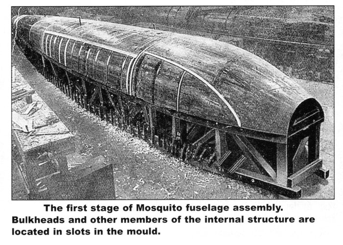
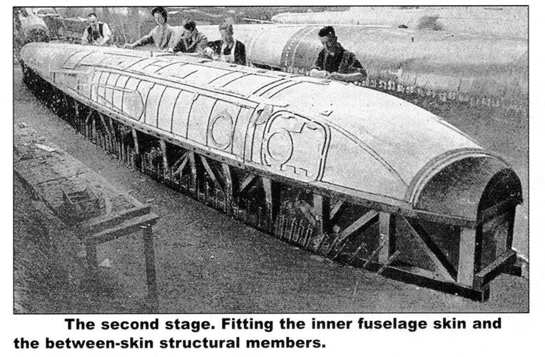
Moskito was more complex than building a Mosquito. The techniques used to build the Mosquito are similar to
methods that had been used in small wooden boat and canoe construction for many decades prior to the Mosquito
existing meaning that setting up new production lines was very straightforward, relatively cheap and could be done
quickly. The only specialized equipment was the moulds, but even those were very straightforward to construct.
Attachments
Last edited:
")