MH53EPilot
ACCESS: Restricted
- Joined
- 11 April 2026
- Messages
- 4
- Reaction score
- 28
Apparently a much earlier study.Would this be a variant of the NASP or X-30?
I don't think so, There were 5 models available at the same time, I only have pictures of two, but believe all 5 were slightly different configurations, (i.e., single fin, dual fin, three fins, etc.) I believe they were wind testing different configurations of the same general shape to see the changes in airflow, stable flight, etc.Is there any chance it could be related to the Dyna-Soar program? I feel like there are some big similarities with the design philosophy, especially around the rear section.
(However, I might be seeing this the other way around, and elements from the Dyna-Soar were utilized in this design instead of vice versa.)
I found this in a NASA document and it looks really close. The B2 nose matches the nose on this model from a Technical Paper by Penland, Creel, and Dillon "Aerodynamic Characteristics of a HRA Having..."Earlier, I would think, just looking at the state of the inscription.
The Orient Express fuselage was less straight, IIRC.
1970-ish or thereabouts…before?
Misc.
View: https://m.youtube.com/watch?v=18LQkgsyGI0&pp=ugUEEgJlbg%3D%3D
Can anyone definitively identify which program this wind tunnel model came from? Would this be a variant of the NASP or X-30?View attachment 808751View attachment 808752eaView attachment 808753
OK, I read the report, took some measurements, and took the model out of the box and I'm 99% sure that I have the center fin model from the NASA report. The dimensions listed in the table for the body 20" long, and dimensions for the center fin match. The other two models mentioned match the other photos that I have of them. In addition the test was conducted at Langley. Everything is matching, so it appears the model that I have was used for a report on Hypersonic Research Aircraft... published in 1978.Great gumshoe work!
OK, I read the report, took some measurements, and took the model out of the box and I'm 99% sure that I have the center fin model from the NASA report. The dimensions listed in the table for the body 20" long, and dimensions for the center fin match. The other two models mentioned match the other photos that I have of them. In addition the test was conducted at Langley. Everything is matching, so it appears the model that I have was used for a report on Hypersonic Research Aircraft... published in 1978.
It's not directly related to the X-24C efforts. The (AIAA) '75 paper you cited states that "Four major categories of high priority research experiments are described as well as the X-24C design concept", but doesn't actually feature the model in question. The PEN00259 pdf file is a mixture of pages from different reports, including the '75 paper mentioned, from the papers of Penland.I was doing some research, and I believe this could still be related to the X-24C.
MODELS
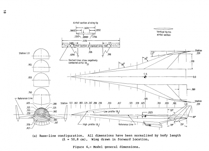
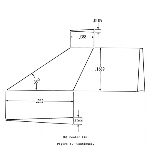
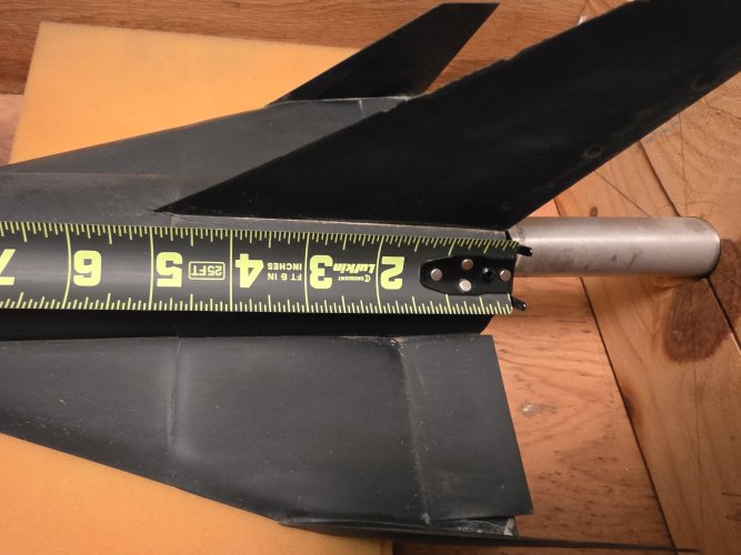
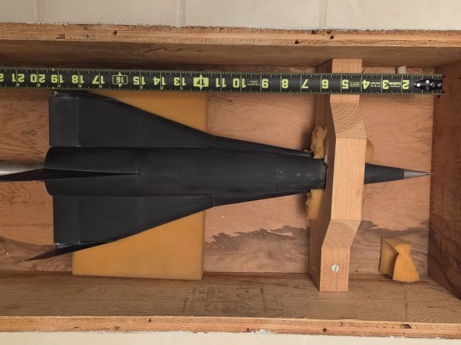
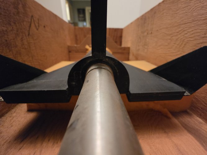
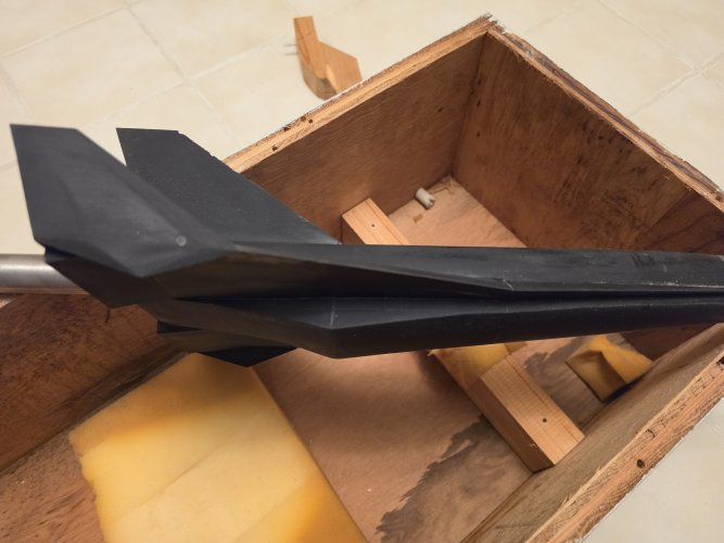
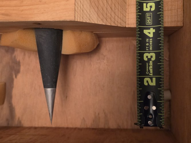
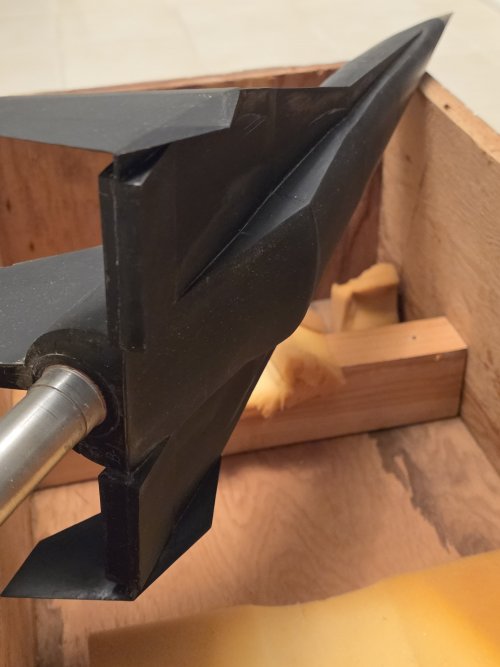
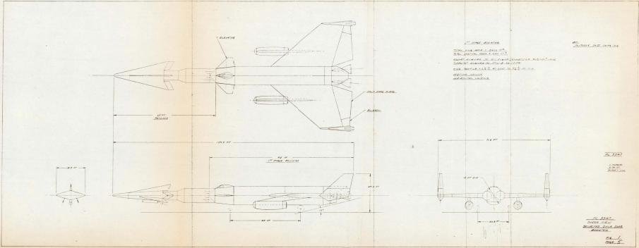
The 0.058-scale test model of a winged hypersonic research aircraft is shown (fig. 1) installed in a low-speed tunnel with a 12-foot (3.66 meter) octagonal test section at the Langley Research Center. The model was of modular design, as shown in figure 2, which allowed the build-up of four variations of the basic model (fig. 3) from two nose shapes, two fuselage base shapes, a forward delta, a positively cambered wing leading edge, a negatively cambered wing leading edge and wing tip fins. The model design rationale was primarily based on the stability and control requirements at the design hypersonic cruise Mach number range of 8 to 10. The two nose profiles are the result of different packaging arrangements. The scalloped base shape was designed to accommodate four rocket motors, one on top and three along the bottom of the fuselage base; however, on a small 0.021-scale hypersonic wind tunnel model the scale base proved to be too small to allow installation of a sting-mounted strain gage force balance. The base was, therefore, modified to the large semi-circular shape to accept the force balance, and was tested on the present large 0.058-scale model. The combination of the two nose and two base shapes made possible the four basic fuselage shapes of the present tests (see symbols list for designation). The forward delta was included in the design to help decrease the rearward shift of the aerodynamic center with Mach number. The negatively cambered wing was theoretically shown to markedly increase the Cmo at hypersonic speeds. Wing tip fins were designed with toe-in and located outboard of the fuselage wake to assure directional stability at hypersonic speeds and were interchanged with center vertical tails for the present tests. A streamlined subsonic center vertical tail and a hypersonic wedge-shaped center vertical tail were tested (fig. 3(b)) to assess the difference in directional stability and the effects on trim as compared with the tip fins. Elevons could be deflected from +5° to -30°. A model scramjet engine was also used to complete the model build-up (fig. 3(c)). The models were constructed of fiberglass and wood with all parts screw-attached and dowel-located on the basic wing-fuselage section. The balance was attached to a steel plate inside the wing-fuselage section. The geometric details of the models are shown in figure 3 and tabulated in table I.
Is P-3473 a Skunk Works designation?
As I know,the only used this high numbered was NAA,North American ?.