A low aspect ratio high-lift aircraft
Abstract: This paper analyzes the main design conflicts of the future fighter's stealth, high maneuverability, and supercruise characteristics while proposing specific design solutions for transonic lift to drag characteristics, low speed high AOA characteristics, and supersonic drag characteristics. The author believes that in-depth study of fluid dynamics, exploration of the full practical potential of current aerodynamic designs, development of new design concepts, employment of corresponding systematic and control measures, and necessary compromise among numerous design proposals will allow us to achieve our design goals.
1. Introduction:
The future fighter, aside from satisfying low and mid-altitude maneuverability performance of modern 4th gen. fighters, must have the capability to supercruise and perform unconventional maneuvers such as poststall maneuvers. As a result, the aerodynamic configuration of the future fighter must not only satisfy the design constraints of RCS reduction but also lower supersonic drag, improve lift characteristics, and improve stability and controllability under high AOA conditions whilel accounting for transonic lift to drag characteristics. The high number of design requirements provide new challenges to the aerodynamic layout. The design must employ new aerodynamic concepts and approaches, take necessary systematic and control measures, and compromise amongst the numerous design points in order to obtain the necessary design solution.
2. Main design conflicts:
The design requirement for stealth brings new difficulties to the aerodynamic design. Frontal stealth capability imposes new restrictions on both the sweep angle of the leading edge and air intake configuration. Lateral stealth requires the proper alignment of the aircraft's cross sectional shaping and the vertical stabilisor configuration. These restrictions and requirements must be considered during the earliest phase of designing the aerodynamic configuration.
Transonic lift to drag ratio and supersonic drag are traditional design conflicts. Modern Fourth gen. fighters successfully solved this dilemma by relaxing aircraft stability and employing wing twist device. Future fighters, however, have stricter requirements for supersonic drag characteristics. At the same time, conventional design maximizing low speed lift characteristics contradicts the pursuit for lower supersonic drag. Since current aerodynamic measures don't offer satisfactory solutions to these conflicts the design team must explore new design paths.
Post stall maneuvers require the aircraft to have good controllability and stability. After the plane enters the post stall region, however, the decrease in stability and control efficiency of conventional rudder surfaces become irrecoverable. One must carefully design an aircraft to enable sustained controllability at high AOA. Although it is possible to solve the problem of post-stall controllability through the use of thrust vectoring nozzles, the aerodynamic configuration itself must provide enough pitch down control capability to guarantee the aircraft to safely recover from post-stall AOA should the thrust vectoring mechanism malfunction. As a result, it is vitally important to study unconventional aerodynamic control mechanisms for high AOA flights.
3. Transonic lift to drag characteristics
Transonic lift to drag characteristics determine an aircraft's maximum range and sustained turn capability. The future fighter's demands for these characteristics will exceed those of modern 4th gen. fighters. Modern fighters employ the strategies of relaxing longitudinal stability, adapting wings with medium sweep and aspect ratio, twisting the wing, and adding wing-bending mechanisms to greatly improve the lift-to-drag characteristics. Due to the future fighter's requirement for supercruise, supersonic drag characteristic is a critical design point and designers must avoid using aerodynamic measures that may potentially increase supersonic drag. As a result, the wing shape and wing twist coefficient can't be selected based on transonic lift to drag characteristics alone. It is necessary to employ wing-bending mechanisms but its aerodynamic efficiency has already been exhausted.
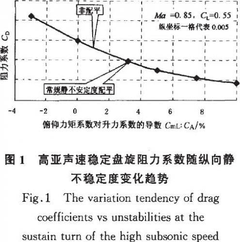
Further decreasing the aircraft's longitudinal relaxed stability is an excellent solution to this problem. Diagram 1 shows how the variation tendency of trim-drag coefficients against longitudinal instability of a conventional fighter aircraft in a tight, sustained turn. Modern fighters fix their longitudinal instability at 3% the average aerodynamic chord length. The future fighter could enjoy a significant improvement in lift-to-drag if the longitudinal instability could be increased to a magnitude of around 10%.
Further relaxing the longitudinal instability could not only enhance transonic lift to drag characteristics but also improve super sonic lift to drag capabilities, increase take-off and landing characteristics, and maximize low-speed lift characteristics. This is akin to killing three birds with a single stone. Yet a increase in longitudinal instability will also increase the burden on high AOA pitch down control and subsequently increase flight control complexities. As a result the design team should not "over-relax" the longitudinal stability.
4. Low speed high AOA characteristics
4.1 Lift-body LERX Canard configuration
Advanced modern fighters utilized research on detached vortices from the 1960s and 70s to gain excellent lift characteristics with their max lift coefficient peaking at around 1.6. They either employ conventional LERX configuration or canard configuration to accomplish this. The future fighter has higher requirements for max lift coefficient and the situation is further complicated by the fact that the use of twin vertical stabilizers is detrimental to lift (see figure 4.2). As a result the design team must raise the max lift coefficient to a whole new level. It will be difficult to realize this goal simply employing conventional LERX configuration or canard configuration.
It is beneficial to choose canard configuration from a high AOA pitch down control stand point(see figure 4.3). Blending lift body LERX characteristics with the conventional canard configuration to form a "lift body LERX canard configuration" will greatly enhance the max lift characteristics. Exploration of the lift body LERX canard configuration will solve three important technical issues. The first problem is the aerodynamic coupling between canards and medium sweep, medium aspect ratio wings. The second problem is the coupling between the canards, the LERX, and detached vortices generated by the wings. The third problem concerns the gains and losses of employing body lift on a canard configuration aircraft.
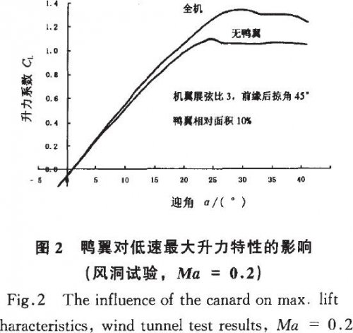
Traditionally close coupled canard configuration aircraft utilize constructive coupling between the canards and detached wing vortices to enhance the max lift coefficient. Only wings with large back-sweep angle and low aspect ratio could generate detached vortices that are powerful enough for the task. As a result most modern canard configuration fighter aircraft have a leading edge backsweep angle of around 55 degrees and an aspect ratio of around 2.5. For these aircraft, the canards could generate around a 3 to 4 times increase in max lift coefficient with respect to their wing areas. Ideally we hope to employ wings with medium leading edge backsweep angle and medium aspect ratio in order to improve lift characteristics over the entire AOA range. This wing shape, however, could not effectively generate leading edge detached vortices. Could the canards still attain their original lift enhancing effects? The answer is yes according to wind-tunnel tests. As the slope of the aircraft's lift curve increases, the lift enhancing capabilities of the canards are the same as those on traditional close coupled canard configuration aircraft (see figure 2). The key influence on aerodynamic coupling between the canards and medium back-sweep, medium aspect ratio wings should not be interference among detached vortices. Preliminary studies indicate that down-wash on the wings generated by the canards play a far greater role.
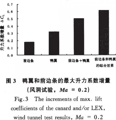
It is a well known fact that LERX could improve the max lift characteristics on medium back sweep, medium aspect ratio wings. In order to obtain even better lift characteristics, we should consider using both canards and LERX to create a canard-LERX configuration. Study shows that employing both canards and LERX not only retain the lift enhancing effects of the two mechanisms when they are used separately but also help achieve higher lift-coefficient (see figure 3). This means that there is beneficial coupling among the canards, LERX, and the wings.
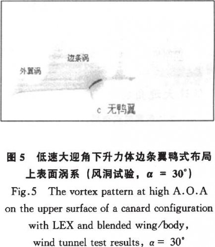
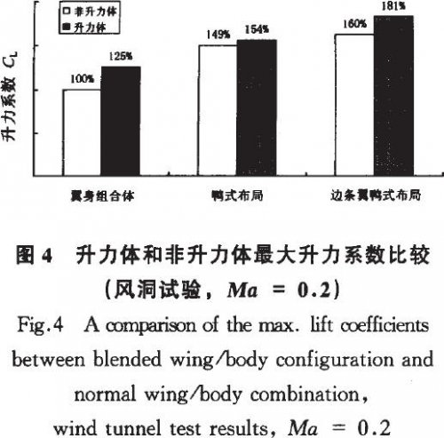
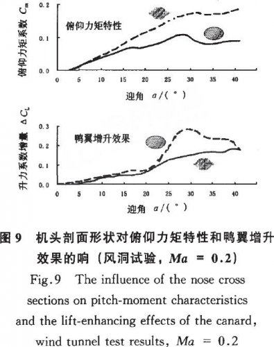
Blended wing lift body configurations could utilize lift generated by the aircraft's body to increase internal load and enhance stealth characteristics at relatively low costs to drag. Lift-body configurations have been adapted by many conventional configuration aircraft and achieved excellent results. Yet until now now canard configuration fighter utilized lift-body configuration. This isn't because aerodynamic experts failed to realize the tremendous advantage of the lift body configuration but the result of a canard configuration aircraft's need to place the canards above the aircraft's wings. It is difficult for lift-body configuration aircraft to satisfy this demand. Our experimental results indicate that although the canards on a canard-LERX configuration aircraft employing lift-body suffered a decrease in lift-enhancing effects, the overal lift characteristic of the aircraft was still superior to that of a canard-LERX aircraft not employing lift-body (see figure 4). Figure 5 shows the vortex generation on the wings and body of a lift-body canard configuration aircraft observed using laser scanning. It demonstrates that planes employing this configuration derive excellent lift characteristics not only from coupling among the canards, LERX, and detached vortices but beneficial interaction between the left and right detached vortices. The latter contribute to significant lift on the body of the plane and greatly contributed to the enhancement of lift characteristics. Figure 5 also indicates that the detached vortices primarily contribute to lift on the body and inner portions of the wings. Consequently, most of the lift produced under high AOA conditions are generated in the corresponding areas.
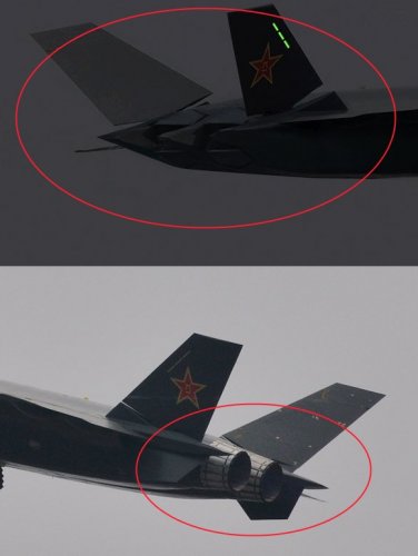
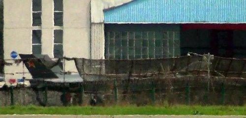
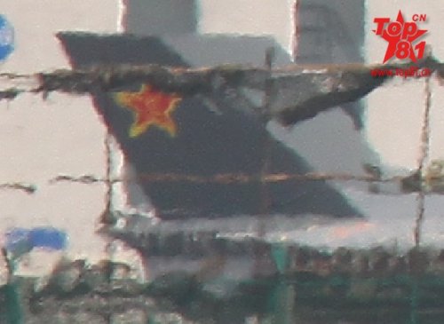
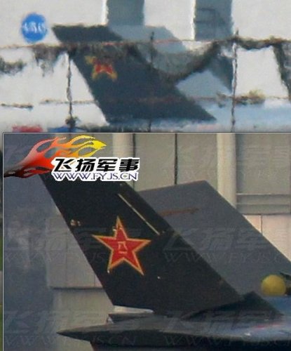
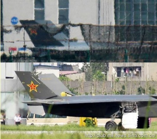
4.2 Canted vertical stabilizers
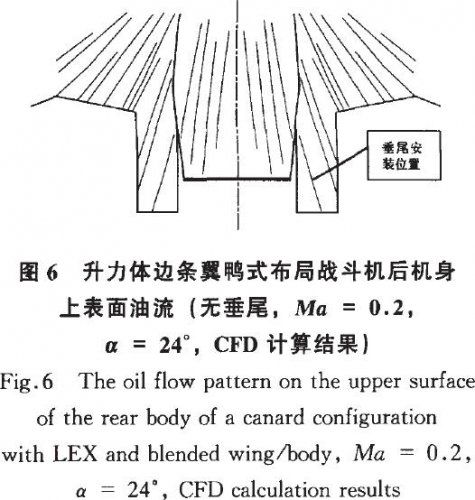
Vertical stabilizer design is an important consideration when it comes to future fighter configuration design. From a lateral stealth stand point, the vertical stabilizers should cant inward or outward to reflect incoming radar waves in other directions. The future fighter must be long and thin to accommodate for supercruise and as a result, the space between the vertical stabilizers couldn't be too wide. The twin stabilizers should cant outward in order to decrease destructive interference between the vertical stabilizers. Since the future fighter will fully utilize detached vortices to improve max lift coefficient, forward vortices will generate relatively high outward facing velocity airflow on the vertical stabilizers. Figure 6 shows the calculation results of a type of lift body LERX canard configuration fighter using n-s time average function. It indicates the limiting flow rate on the aircraft's rear once the vertical stabilizers are removed. The results indicate that the regional side slip angle at the location where vertical stabilizers are usually installed reaches around 15 degrees when the AOA is 24 degrees and the side slip angle is 0 degrees. If the back-sweep angles of the vertical stabilizers are sufficiently large, the enormous regional side slip angles could generate leading edge shed vortices on the external faces of the stabilizers and form low pressure regions. Regional sideslip angles will also increase the static pressure on the inner portions of the vertical stabilizers. As a result, the vertical stabilizers will become highly efficient lateral force surfaces which direct the lateral forces outwards. The lateral forces are projected in the direction of lift, with respect to the outward canting vertical stabilizers, and generate negative lift. Negative lift acting on the vertical stabilizers and rear body will both contribute to the undesirable pitch up torque. The high pressure region between the vertical stabilizers will form adverse pressure gradients on the body of the plane and negatively impact the stability of leading edge detached vortices. Since the vertical stabilizers are already highly loaded at 0 degree side slip angle, the yaw/roll stabilization efficiency of the vertical stabilizers will be decreased.
The negative impacts of vertical stabilizers as described above are closely associated with lift-enhancing measures and are, as a result, difficult to root out. Yet adjustment of the vertical stabilizer’s area, position, cant angle, and placement angle and improvement measures such as making slots on the rear body can minimize the negative impact of the vertical stabilizers. Ordinarily, the max lift reduction coefficient generated by the vertical stabilizers could reach around 0.4. We’ve managed to successfully lower it below 0.1 through experimentation.
Decreasing the vertical stabilizers’ area or even employing tailless configuration are directions worth studying. Their significance not only include improving low speed high AOA performance but also help improve stealth characteristics, lower drag within the entire flight envelope, decrease weight, and reduce cost. Implementing the tailless configuration requires the tackling of three major technical difficulties: replacing the stabilizers with another yaw control mechanism, installing sensitive and reliable side slip sensors, and implementing new flight control technology. As of now, these difficulties are being tackled one at a time. Relatively speaking, decreasing vertical stabilizers’ area and relaxing static yaw stability are more realistic options. Generally speaking, the relative size of the vertical stabilizers is around 20% to 25%. In or studies, utilizing all moving vertical stabilizers with 10% to 13% could still maintain basic yaw stability while retaining the vertical stabilizers’ function as yaw control mechanisms.
4.3 Aerodynamic control mechanisms
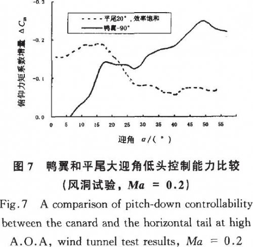
The requirement for high AOA pitch down control capability is closely related to the longitudinal static instability requirement. The greater the longitudinal static instability, the higher the demands for pitch down control capabilities. As described in chapter 3, the future fighter will hopefully increase its longitudinal static instability to around 10% its average aerodynamic chord length to enhance the trim's lift to drag and lift characteristics. As a result there should be a corresponding improvement in the pitch down control capability. We can categorize two types of control surfaces based on the relative position of the pitch control surfaces with respect to the aircraft's center of mass: positive load pitch down control surface and negative pitch down control surface. Control surfaces placed behind the center of mass, including the vertical stabilizers and trailing edge flaps, generate pitch down control torque by increasing lift. They are considered positive load control surfaces. Control surfaces placed in front of the center of mass, like the canards, are negative load control surfaces. Since the main wing's ability to generate lift tends to saturate under high AOA conditions, the positive load control surfaces' pitch down control capabilities tend to saturate under high AOA as well. Therefore it will be wise to employ negative load control surfaces for pitch down control under high AOA conditions. Figure 7 compares the pitch down control capabilities of the canards and horizontal stabilizers. From the high AOA pitch down control stand point, it will be wise to use canards on the future fighter. Canards on close coupled canard configuration aircraft have relative short lever arms. Employing the LERX canard configuration can increase the canards’ lever arms while retaining the benefits of positive canard coupling. Considering the overall lift enhancement effect and pitch down control capabilities, we can set the canards’ maximum relative area to around 15% and the maximum canard deflection to 90 degrees.
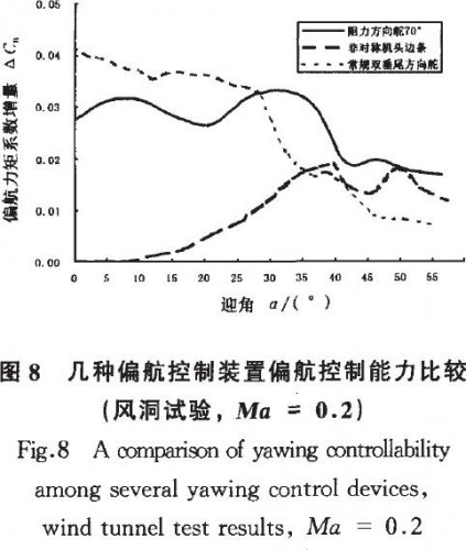
Yaw control ability under high AOA is another noteworthy problem. Control surface efficiency deteriorate rapidly with an increase in AOA for tailless and even conventional configuration fighters. Therefore it is necessary to consider control mechanisms other than conventional control surfaces. Studies on differential LERX, drag rudder, differential wingtips, and all moving vertical stabilizers indicate that differential LERX and drag maintained relatively high yaw control efficiency under high AOA conditions (see figure 8).
5. Supersonic drag characteristics
The key to lowering supersonic drag is to minimize the max cross sectional area of the aircraft.Accomplishing this requires excellent high level design skills. Placement of the engines, engine intakes, landing gears, cartridge receiver, weapons bay, and main structural support all influence the max cross sectional area of the aircraft. Attention to details and careful considerations are necessary to design decision making.
Wingshape has profound effects on supersonic drag characteristics. Low aspect ratio wings with large backsweep have low supersonic drag but are detrimental to low speed lift and transonic lift to drag characteristics. If we select the liftbody LERX canard configuration we can expect to retain relatively good lift to drag characteristics while using medium backsweep wings. Under high AOA conditions, liftbody LERX canard configuration aircraft concentrate lift on the body and inner portions of the wings so moderately lowering the aspect ratio will not only not lower the max lift coefficient but raise it (see figure 10). Because of this, employing low aspect ratio wings on a lift-body LERX canard configuration aircraft will settle the conflicts among supersonic drag characteristics, low speed lift characteristics, and transonic drag characteristics.
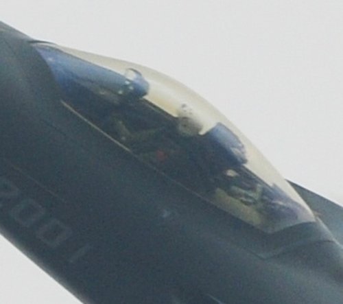
6. Air Intake design
Air intakes are one of three major sources of radar scattering. In order to lower intake radar reflection area, the design team must place a series of limitations on intake design due to stealth considerations. These limitations will significantly influence intake aerodynamic design.
Caret intakes have oblique intake openings and fixed intake ramps and could effectively lower radar cross section and structural weight. The future fighter may implement this technology. Preliminary studies indicate that when compared with conventional adjustable intakes, Caret intakes' total pressure recovery coefficient surpasses its conventional counterpart in supersonic and transonic regimes and is only slightly lower in the low-subsonic regime. It also offers excellent total pressure distortion performances. Radar absorbing deflectors minimize the air-intake's radar reflection and could significantly improve its stealth characteristics. Aerodynamically speaking, the radar absorbing deflectors would slightly decrease the overall pressure recovery and flow coefficients but have no ill-effects on static or dynamic distortion coefficients.
7. A comprehensive study of a design example
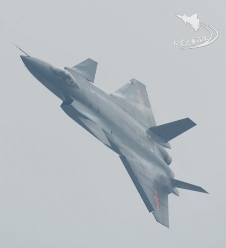
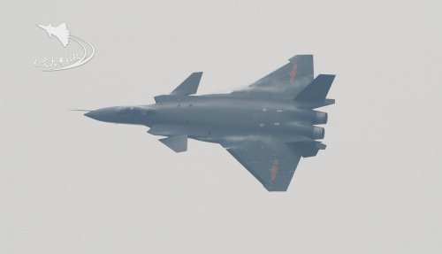
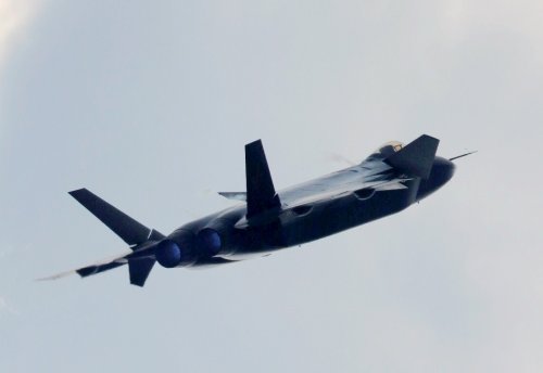
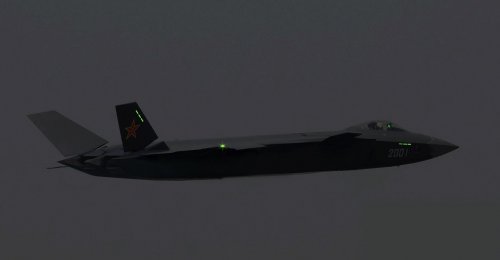
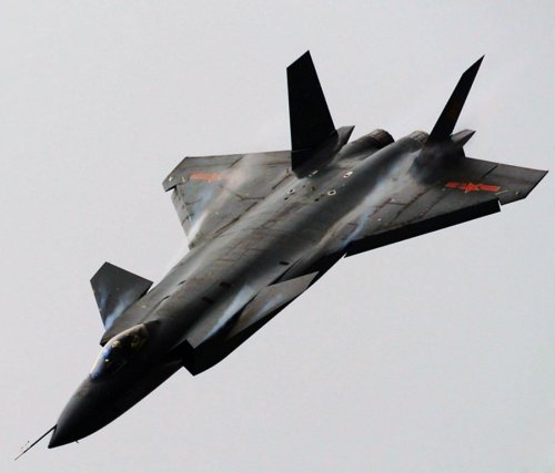
The design team made a future fighter proposal based on the points raised by this article. The proposal employs lift-body LERX canard configuration. It is unstable in both the lateral and yaw directions. The proposal employs low aspect ratio wings with medium back sweep angle, relatively large dihedral canards, all moving vertical stabilizers far smaller than those on conventional fighter aircraft, and S-shaped belly intakes. According to our assessment, the proposed aircraft will have excellent supersonic drag characteristics, high AOA lift characteristics, high AOA stability and controllability, and excellent stealth characteristics.
8. Conclusion
The aerodynamic design for the future fighter, compared with that of advanced modern fighters, will require more design features and subsequently pose greater challenges. Only in-depth study of fluid dynamics, exploration of the full practical potential of current aerodynamic designs, development of new design concepts, employment of corresponding systematic and control measures, and necessary compromise among numerous design proposals will allow us to achieve our design goals.