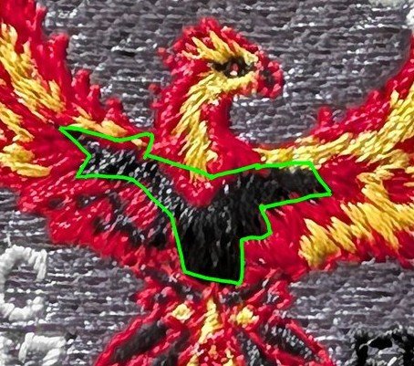
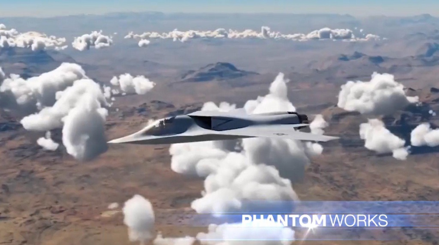
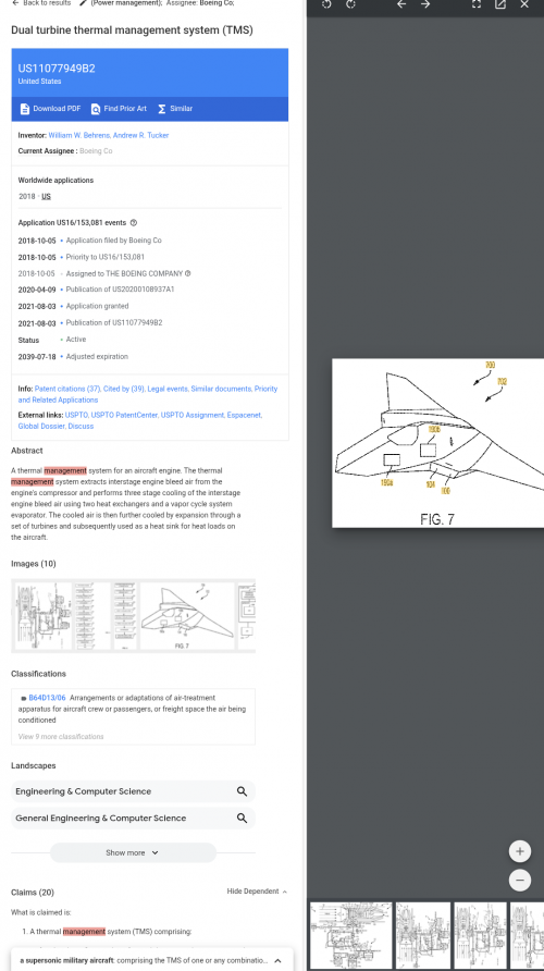
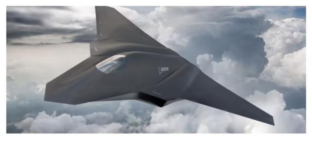
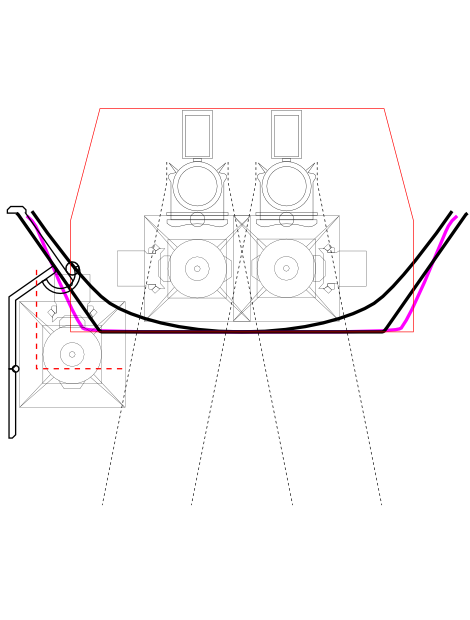
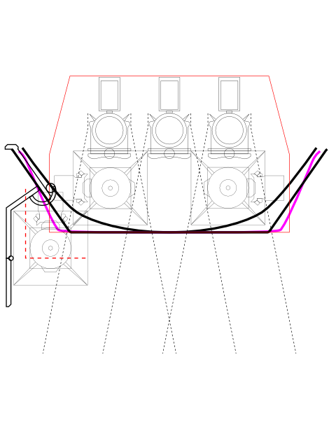
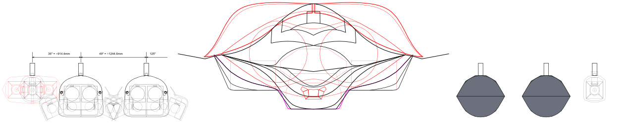
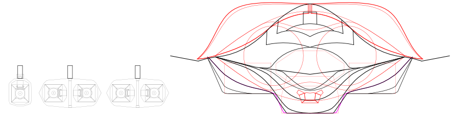
Very good! I didn't get good results with Gemini in the tests I did. Do you have the paid version? Can I ask what instructions you gave it to generate these images? They look a lot like the FA-XX that Boeing presented in its latest image.
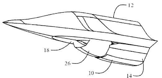
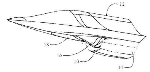
I use the paid version of Gemini and employed the "nano banana" tool. I sent the two images that have already been released, in addition to requesting research on Boeing Phantom Works. I also forwarded images of the YF-118G and the X-36, although sometimes the results are not ideal. The best approach seems to be to start new conversations after obtaining a satisfactory result; I also used the patch drafts below as a reference 1000308992.jpg 1000308962.jpg 1000308953.jpg 1000308960.png
 
Hi!
I wanted to ask if anyone could share the link to the forum where the images of Boeing's variable DSI patent are located. I've been looking for it for quite some time, but I can't find it.
Thanks a lot.
 
This is the PDF. Interested in how that cowling is going to work on a stealth fighter.
Thanks, Reddington.
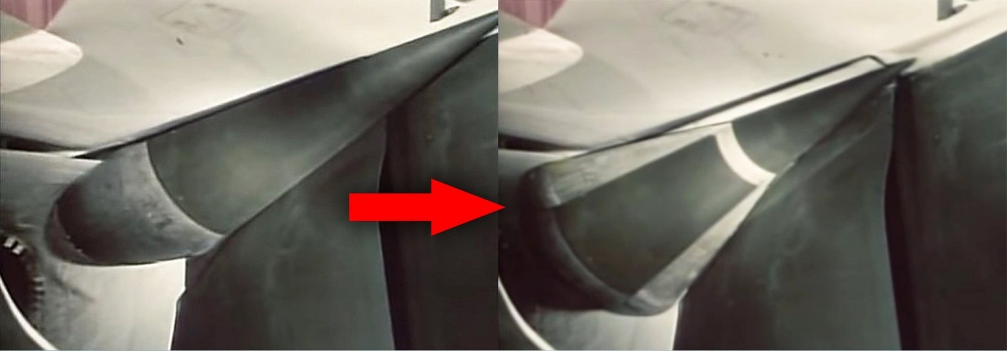
I was also referring to the patent with a DSI featuring a flexible skin and an internal rotating, snail-shaped mechanism.
I'm working on a new F47 model and wanted to see that patent, but I can't find it on the forum.
On another note, I hadn't seen the PDF you shared. It's curious that it's dated 2016 when we know the Boeing demonstrator flew in 2018.
This intake would be the evolution of all Boeing ventral intakes, with a surface that moves forward.
01.jpg

02.jpg
It seems the people at Boeing were working and thinking a lot about the air intakes before the flight of their technology demonstrator for the Navy.
If anyone has the forum link to the Boeing patent with the flexible skin DSI and a snail-shaped mechanism, I would greatly appreciate it.
Regards and thanks!
 
A notable afterthought, the patent shows the intakes on the underside, but I am certain this is done to mislead. This has to be the intake configuration for the one everyone deemed ugly. Id top mount it. If you look too, the frontal cross sections cockpit almost looks superimposed.
There's this bit describing how it works:
As the spiral cone is rotated about its central axis of rotation, surfaces on the aircraft adjacent to the exposed edges of the spiral cone retract to follow the
spiral cone profile to thereby receive the increasing radii portions of the spiral cone as the exposed compression surface area increases.
As described, it isn't just the cone that's moving but the surrounding aircraft skin exposing the cone moves with it, but perhaps these structures could be hidden entirely if there's flexible aircraft skin stretched completely over the DSI cone. Then it may or may not look different then from current DSI from the outside. Youd have to make sure the actual skins shape is carefully shaped by the snail shell and surrounding structures underneath (I really don't like the thought of magical flexible aircraft fixing everything though so this might just be me spitballing).

@targetpractice with the cowling design, I'm not sure how they would hide the gap of that cowl because as depicted it doesn't look small at all...can't flexible-aircraft-skin myself out of that one considering how far forward it has to move..
 
Last edited:
Given how the F-47 renders seem to be, I don't think a cheek array would make sense on the forward fuselage. The upper fuselage above the chine basically runs 50 - 60 degrees facing upwards while the fuselage under the chine runs the same degrees facing down. Any arrays on either surface would need to steer high off boresight to be able to search co-altitude.

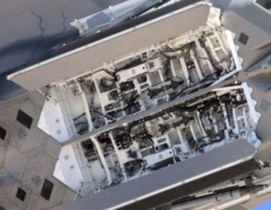
I read that the general dynamics ATF design apparently had two radar arrays in the leading edge extensions. So thinking about other places that could accommodate an actually useful side looking array ....
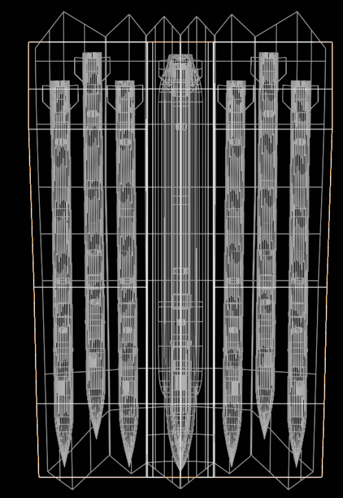
For a side looking array, how feasible would it be to stick a side looking array on the fuselage, like where the F-22's AIM-9 bays are but just in front of the wing's leading edge?
1767328468765.png

The current examples of side looking arrays are all boresighted down by 20 - 30 degrees, which seems to mean that the intended scan volume may not have high requirements for targets higher in relative elevation. With a high leading edge sweep and dihedral, an array where the AIM-9 bays are would have a decent FOV in azimuth and in elevation. It would depend on the intake and how much depth the cheek array needs too. As far as I can tell, a lot of nose and side apertures have a "brick" that's 8 - 10 inches. Just what else needs to go behind the array, I'm not sure, but if an AIM 9 and it's weapons bay could fit there, then one would think an array stack of 8 - 10 inches deep should too...

Another idea is to have the array sit behind the chine. Radomes have chines for the frontal array so would it be prohibitive to have a chine running across a frequency selective cover on the side? RF wise I'm not sure what kind of interference or problems that might introduce.

1767332703907.png
 
Last edited:
For a side looking array, how feasible would it be to stick a side looking array on the fuselage, like where the F-22's AIM-9 bays are but just in front of the wing's leading edge?
Volume-wise I'm sure it'd be fine. We can handwave power and cooling under the assumption that they'd be designed in.

But I'd prefer an AMRAAM-sized side bay and put the "side arrays" into the LE flaps/slats. A side bay would allow engaging an air target while leaving the open bay in the radar shadow. Surprise AAM without RCS spike.
 
But I'd prefer an AMRAAM-sized side bay and put the "side arrays" into the LE flaps/slats. A side bay would allow engaging an air target while leaving the open bay in the radar shadow. Surprise AAM without RCS spike.
That is true, but with regards to array size and field of view, LE flaps and slats mainly expand the frontal sector detection, but they don't contribute as much to side detection / holding tracks while evading. The side weapon bays would only be able to hold one extra AAM each anyway.
 
That is true, but with regards to array size and field of view, LE flaps and slats mainly expand the frontal sector detection, but they don't contribute as much to side detection / holding tracks while evading. The side weapon bays would only be able to hold one extra AAM each anyway.
So, side array with a Su-57 style "armpit bay" for the surprise AAM?
 
Well, on my design there's a way to mount these small arrays for full 360° coverage for radar/EW (ALQ-249 sized). I just haven't set on bay door arrangement yet. The key idea is to arrange around the DEW placement.
Since, it's gonna be flying high 65+kft most of the time the top coverage won't be a problem. Most CCA (targets) won't be flying higher than 50kft. And being on standby station will mean watching the sides more often than the front or aft as they fly their circus-esque orbits.
 
The simple or primary DEW location would be the IWB. The other options would be the "inner" side bay locations in my flattened body design:
View attachment 797218
This is a rough fitting outline. It may not look it but the lines are complicated (multiple S-curves).
Sorry I also meant to ask about the side looking RF apertures - where did you intend on mounting those?
 
Sorry I also meant to ask about the side looking RF apertures - where did you intend on mounting those?
Not so different from the "usual" the main differences would be on the dorsal intake which could be used to hide the antenna (inside sllopes) as well as offering vertical orientation. The fuselage sides could also be used but interferrence with the side arrays need to be checked...
F47-RF-arrangement.png
 
I saw he recent discussions and realize there are some uncertainty about sensor LOS and IWB etc.
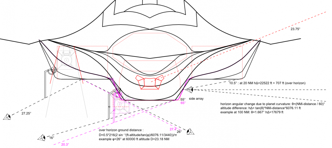
So this is my illustration on my current particullar design iteration to answer many of those question and showcasing the problems I've.
So first about the sensors, LOS and IWB. Originally, I started with a simple solution then I tried an aerodynamically desired solution and finally a compromised inbetween. As it turns out the original offered the best "stealth" but also the worse clearance. More on that in the next post.
F47-LOS-front-side-angles.png
As you can see the original (vilolet) IWB outer skin outline offered the tightest visual/RCS coverage from the ground.
The aerodynamic one is the inner curvature. The current one is the more slanted and wider open example.
weapons_bay-cross-section_compare-rectangle2triangle.png
I actually tried to get to a triangular form but it wouldn't work out with the stores.
Anyhow, as for the LOS; Earth's curvature gives an advantage for the sensors to detect higher located targets the further they are. But likewise exposes the open IWB to greater distances on the ground.
My reason for the separated IWBs was to minimize this while ensuring complete side coverage where the most aereal detection and engagement danger lurks. As well as missiles coming from the side have the highest hit probability afaik.
My EOTs design may not look like it but it's as flat as possible while also offering large elevation arc to the sides than on the F35. This is to account for higher speed requirement and side view needs (just like the J-50).
I'm not happy with the side bay's exposure. A better solution would be like the SU-57 and the German DLR-FFD v5. But they might interfer with the inner wingstation. So I'm still not set yet.
 
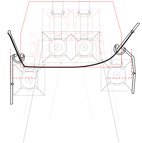
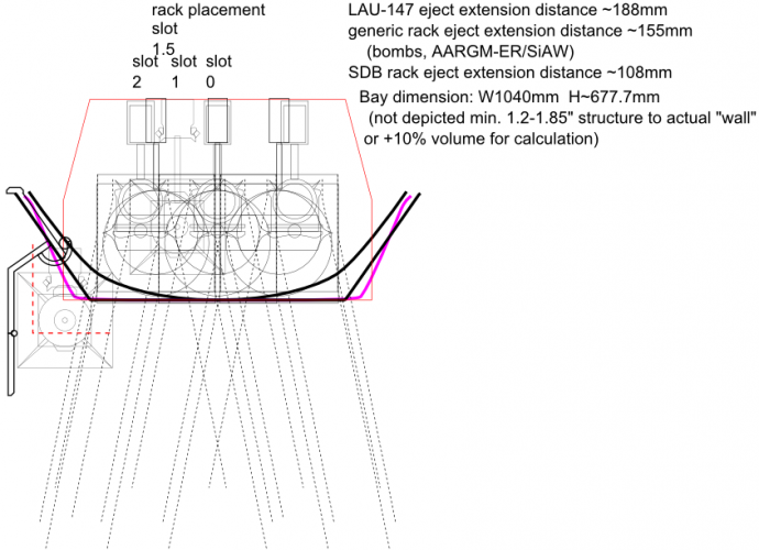
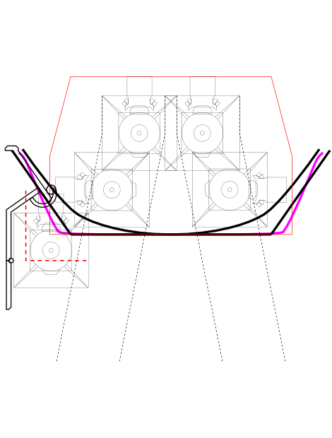
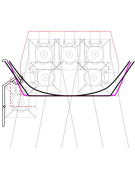
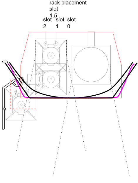
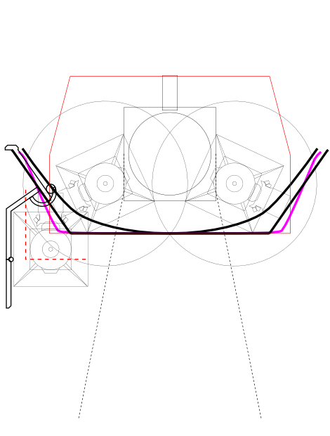
Now to the IWB specific problems regarding clearance and arrangement. All these are just for illustration purposes and may not in any way reflect the real thing, although things shouldn't be too different. The main uncertainty lies with the sizing and location of the frames where the racks are mounted. I believe older standard racks are not suitable for IWB use due to their bulk and bolt attachment points.
From what I see Boeing got a new patent on a new universal rack based on good old gravity locking. I'm using it for most everything except for the SDB which is based on the externall pod design patent. The AIM120/260 uses the LAU-147. Without exception all are ejection type. I don't think rail types should be used as A2A needs them ejected while rolling and maneuvering not while static like bombing.
I do desire to pack a bottom layer of missiles but I do not consider this a must be requirement. I also see a rare need to pack 2000 lb bomb/GBU72 penetrator (2000 lb size)/B61 (1000 lb size) but I do not consider them generally used all the time. I consider them high value target strike packages needed on a first wave needed case if ever. A2A is the primary mission with SEAD and mobile balistic launchers as secondary. This is where time critical AARGM-ER/SiAW are needed. I consider them part of PCA's main armament.
CAS is out of the quesstion, although, SDB/SPEAR and other similar new smart stores should cover this if needed.

The first key issue is the placement of the racks and their fixation onto the frame. Current racks use a number of bolt and screw at the side and or at the top depending on the pylons etc. Based on the F22 everything fits fine except for the bomb racks which is kind of always in between the other types. Also current ones use a spring-pin pneumatic(gas) ejection system.
F47-center-IWB1040mm-rack-illustration.png
The open door and missile pair is just for illustration and showcasing clearance. It's not final but I can always make it work for any desired location regardless. It's just the door limits side placement. The red dashed (box) line is the desired location for the missile's (center). Not necessarily but just for aiming purposes.
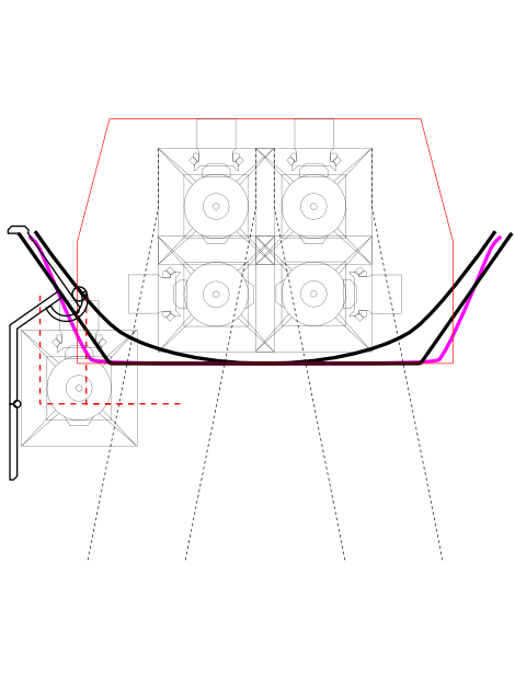
Now just for the heck of it - various packing solutions:
F47-center-IWB1040mm-4AIM-v1.png F47-center-IWB1040mm-4AIM-v2.png F47-center-IWB1040mm-5AIM.png F47-center-IWB1040mm-GBU+2AIM-v1.png F47-center-IWB1040mm-GBU+2AIM-v2.png F47-center-IWB1040mm-SDB-dual.png F47-center-IWB1040mm-SDB-triple.png
Btw. AARGM-ER/SiAW take same position as the 1000 lb bomb location as illustrated. 2 x 1000 lb can be mounted and only a single 2000 lb fits in the center so I skipped them due to redundancy.
As you can see fitting the 2nd layer of missiles is possible but there's no single placement fit-all-solution. The only good news is it's mostly on the same horizontal axis. I can make them all work and taking the same open launch position but each one requires a different rotation point location. It's possible to design a variable rotation axis but it would be prone to mechanical failure and re-adjustment for every sorty.
 
Last edited:
For completeness, here's the wingstation illustration and related spec calculation.

F47-wingstations-1.png
As you can see the constellation of Boeing pods (patents: US9180967B2, US20240328752A1) aren't well suited to work together. As I've noted before large load out pods aren't practical unless all stores can be used up before the fighter get's in trouble. This is especially true for those acting as the spear not so much for those acting as support.
This is more like it with my fancy little pod design:
F47-wingstations-2.png

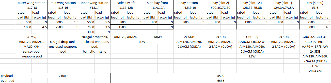
Now to the specification table. It's conservative and based on load factor standards used with the F16. The F22 with the 6g requirement at Mach 1.8 would only be 0.5 g more for the wing stations. So it barely differs.
F47-store-station-payload-load-factor.png
The stations are numbered based on actual practical use rather than their raw existence.
As per standard maneuvering with A2G stores is limited to 4-4.5 g but as seen with the new cheap Anduril missiles it could be limited to 3g.
 
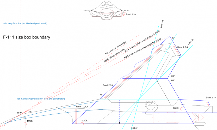
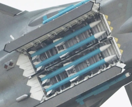
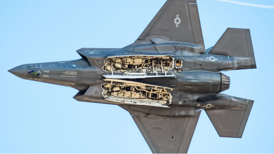
When you guys are designing the weapons bay, are we taking into room needed for these slanted sections for flow management at the back
Are you talking about how the serrated section in the back usually goes past the end of the weapon bays?
1767677002003.png
I did on mine I think.

The front of the weapons bay I didn't really obey the "box" and opted for what the F-35 has, though they could be extended further forward without a problem.

1767677528840.png

The trailing part of the bay doors I generally made sure that the trailing serrated edges would start well outside of the "box". They could now be afforded a bit more space since I decided to drop my aft weapon bay.

(My engines were not leaving enough believable clearance space to the nacelle frames so I had to drop the aft weapons bay and moved my engines closer together where there was more height available to avoid tampering with the volume)
 
When you guys are designing the weapons bay, are we taking into room needed for these slanted sections for flow management at the back
Yes, all my drawings have the space included with the door allocation, but it's not that necessary. The F35 doesn't really have it nor all previous aircrafts.
More importantly are the front freestream deflecter & acustic tuner/airbreak without which stores can't be dropped safely and vortices and vibrations woulld cause havoc.
 
Are you talking about how the serrated section in the back usually goes past the end of the weapon bays?
View attachment 797650
I did on mine I think.

The front of the weapons bay I didn't really obey the "box" and opted for what the F-35 has, though they could be extended further forward without a problem.

View attachment 797651

The trailing part of the bay doors I generally made sure that the trailing serrated edges would start well outside of the "box". They could now be afforded a bit more space since I decided to drop my aft weapon bay.

(My engines were not leaving enough believable clearance space to the nacelle frames so I had to drop the aft weapons bay and moved my engines closer together where there was more height available to avoid tampering with the volume)
It looks like the small, open door behind the left weapons bay is for the flares?
 
It looks like the small, open door behind the left weapons bay is for the flares?
Yes, that bay is for flares but it's on the right side. The image above is mirrored.
That said it seems in the future BriteCloud smart decoys might be there. I'm not sure about that as it makes more sense for them to be in the decoy towing bay instead. After all flares should still be needed.
 
Yes, that bay is for flares but it's on the right side. The image above is mirrored.
That said it seems in the future BriteCloud smart decoys might be there. I'm not sure about that as it makes more sense for them to be in the decoy towing bay instead. After all flares should still be needed.
Got it, thanks.
 
No problem.
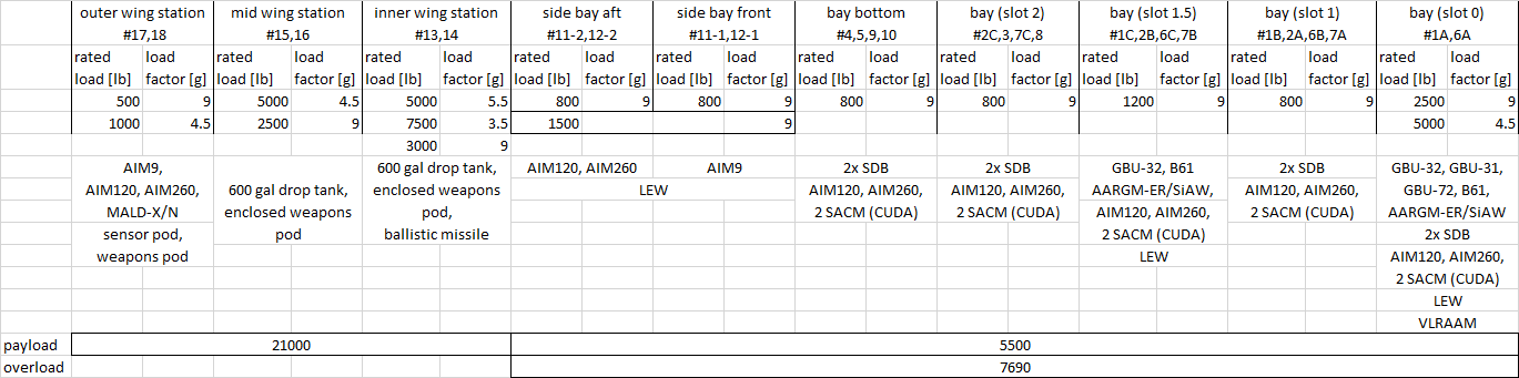
Anyhow, after adopting the station table for the F/A-XX discussion I realized the numbered counting was flawed and not representative of how many are in use based (on the counting). It's probably more confusing. -.-;
Also I fixed the overload number as it wasn't properly updated. The cause is frankly the difference between AIM120 and AIM260 weights. It's an oversight. In the scheme of everything the difference of ~2200 lb won't impact too much on performance and represents less than 5 min of full burn.
F47-store-station-payload-load-factor-v2.png
 
Are you talking about how the serrated section in the back usually goes past the end of the weapon bays?
View attachment 797650
I did on mine I think.

The front of the weapons bay I didn't really obey the "box" and opted for what the F-35 has, though they could be extended further forward without a problem.

View attachment 797651

The trailing part of the bay doors I generally made sure that the trailing serrated edges would start well outside of the "box". They could now be afforded a bit more space since I decided to drop my aft weapon bay.

(My engines were not leaving enough believable clearance space to the nacelle frames so I had to drop the aft weapons bay and moved my engines closer together where there was more height available to avoid tampering with the volume)
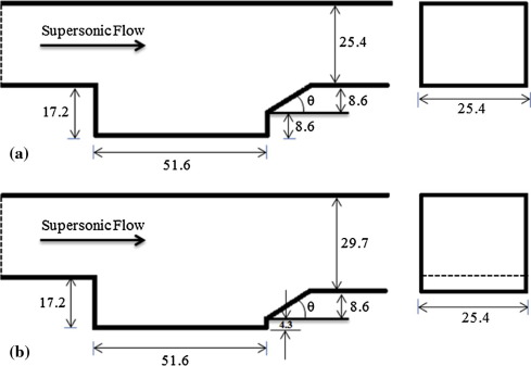
Finally figured out the technical term for it, "aft cavity ramp"
1767762047895.png 1767762095034.png
I'm reading more into currently myself, but it's a means of controlling how supersonic flow interacts with the weapons bay cavity, like managing pressure resonance and shear layer oscillations.

I think there are various reasons why the F-35 doesn't feature the ramp but I'm not entirely sure if such reasons would also work for NGAD. Just as an observation of roles, the F-35 serves sort of a multirole/strike role, while empirically all the other air superiority focused stealth aircraft feature it.
 
Last edited:

Similar threads

Back
Top Bottom