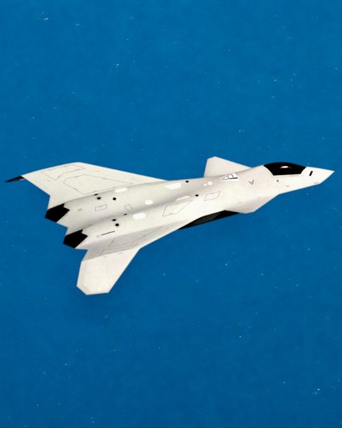
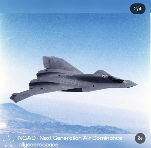
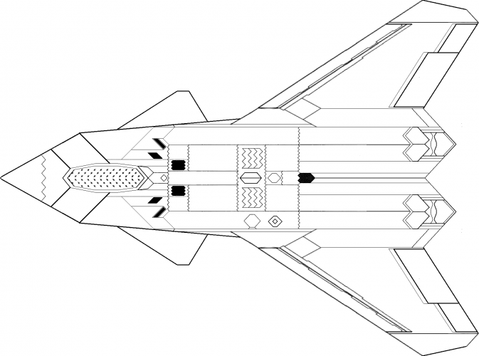
Hello, new to the site. Done plenty of similar research on configurations, checking internal volumes, et cetera. I've put together many variants of my own speculative design on Instagram. I am really just commenting here to say I am stunned by Reddington's initial wing planform guess, way before this thermal leak. The lambda and double chevron thing at the aft. Almost exact geometry. I've never seen a guess so good. Attached, just for fun, are some renders of the model I put together.

You are using an out of date browser. It may not display this or other websites correctly.
You should upgrade or use an alternative browser.
You should upgrade or use an alternative browser.
CGI - Possible configuration of the Boeing F-47 NGAD
- Thread starter 4decaa
- Start date



- Joined
- 27 December 2005
- Messages
- 19,230
- Reaction score
- 35,692

This is exactly what I imagined. Nice job.
insidersource
ACCESS: Top Secret
- Joined
- 24 March 2025
- Messages
- 521
- Reaction score
- 745
That outer wing tip would also have enough ground clearance where it could fold straight down for a carrier version. This also allows for a much lighter folding mechanism compared to the traditional upwards folding wing tip. The lift created during flight would naturally cause it to stay in the up/locked position. That is extremely smart engineering.
Close to what I'd imagine too, try it with the intakes on top of the fuselage ?This is exactly what I imagined. Nice job.
Last edited by a moderator:

FighterJock
ACCESS: Above Top Secret
- Joined
- 29 October 2007
- Messages
- 7,256
- Reaction score
- 8,570
Air intakes on top of the fuselage? That would be counter productive to supermaneuvrability.

Reddington777
ACCESS: Top Secret
- Joined
- 23 March 2025
- Messages
- 848
- Reaction score
- 2,800
I dig the ventral intake and DSI
Scott Kenny
ACCESS: USAP
- Joined
- 15 May 2023
- Messages
- 19,654
- Reaction score
- 28,133
I'd love that as a 3d print file...Hello, new to the site. Done plenty of similar research on configurations, checking internal volumes, et cetera. I've put together many variants of my own speculative design on Instagram. I am really just commenting here to say I am stunned by Reddington's initial wing planform guess, way before this thermal leak. The lambda and double chevron thing at the aft. Almost exact geometry. I've never seen a guess so good. Attached, just for fun, are some renders of the model I put together.
Now I just need to come up with Check Your Six stats for the beast.

EmoBirb
ACCESS: Top Secret
- Joined
- 18 January 2025
- Messages
- 2,714
- Reaction score
- 6,959
Which is of little relevance for modern network centric warfare. The F-47 ideally never has to conduct WVR combat.Air intakes on top of the fuselage? That would be counter productive to supermaneuvrability.
When you have a squadron of sensors and weapons carriers that fly out, as well as carrying potent sensors and long range missiles yourself, your aircraft can be a literal pig in the air.


- Joined
- 6 August 2007
- Messages
- 4,539
- Reaction score
- 10,259
Which is of little relevance for modern network centric warfare. The F-47 ideally never has to conduct WVR combat.
Well, life can be full of little short ranged surprises.
By that logic, the B-21 with a flock of CCAs would be sufficient. A whole lot of analyses has determined it isn't.When you have a squadron of sensors and weapons carriers that fly out, as well as carrying potent sensors and long range missiles yourself, your aircraft can be a literal pig in the air.
insidersource
ACCESS: Top Secret
- Joined
- 24 March 2025
- Messages
- 521
- Reaction score
- 745
This image perfectly highlights why the landing gear appears so tall in the night vision video.
The wing tip in this rendering is far too close to the ground to handle a cross wind landing. This design needs a very tall landing gear. Also consider the Boeing demonstrator was designed for the Navy that rendering has insufficient clearance for a tail hook. The height of the landing gear would probably have to double.
The wing tip in this rendering is far too close to the ground to handle a cross wind landing. This design needs a very tall landing gear. Also consider the Boeing demonstrator was designed for the Navy that rendering has insufficient clearance for a tail hook. The height of the landing gear would probably have to double.
Attachments

Last edited by a moderator:
EmoBirb
ACCESS: Top Secret
- Joined
- 18 January 2025
- Messages
- 2,714
- Reaction score
- 6,959
There's quite a difference between a not-so-maneuverable supersonic fighter jet and a subsonic strategic bomber. I'm unsure why I have to even point this out.By that logic, the B-21 with a flock of CCAs would be sufficient. A whole lot of analyses has determined it isn't.
- Joined
- 6 August 2007
- Messages
- 4,539
- Reaction score
- 10,259
Also consider the Boeing demonstrator was designed for the Navy that rendering has insufficient clearance for a tail hook.
Please provide your evidence that supports these statements.
insidersource
ACCESS: Top Secret
- Joined
- 24 March 2025
- Messages
- 521
- Reaction score
- 745
Please provide your evidence that supports these statements.
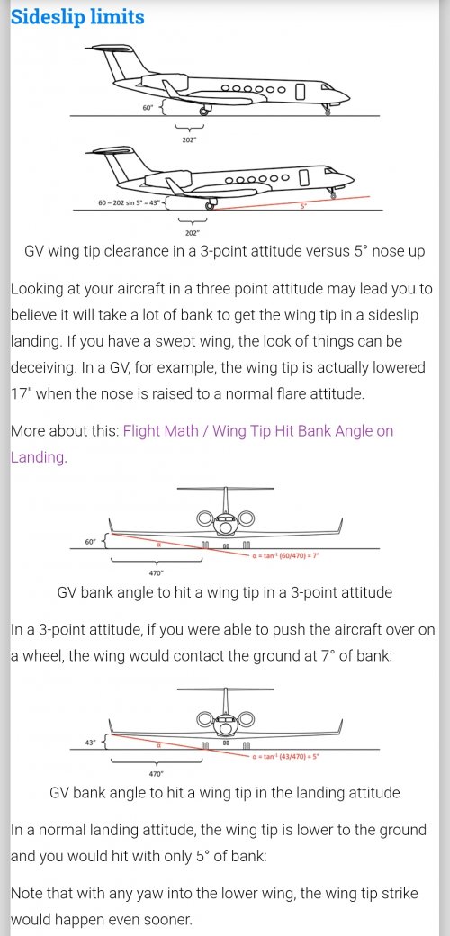
Here is some flight math for you.
https://code7700.com/flight_math.htm#wingtiphit
There are clear design rules for engine and wing tip clearance. Countless examples where fitting new larger diameter engines had ground clearance issues. These engines are also half way down the wing. The wing tip in this rendering is extremely close to the ground. Even a slight 5 degree bank angle has it hitting the ground.
You keep requesting evidence for things that are so blatantly obvious. I beg you to not reply to this message as the evidence has been provided. The artist can tweak their rendering if they want.

red admiral
ACCESS: Top Secret
- Joined
- 16 September 2006
- Messages
- 2,199
- Reaction score
- 3,472
You haven't provided any "evidence" that's related to tail hook location and / or geometry.You keep requesting evidence for things that are so blatantly obvious. I beg you to not reply to this message as the evidence has been provided.

donnage99
ACCESS: Top Secret
- Joined
- 16 June 2008
- Messages
- 1,586
- Reaction score
- 1,640
if your design relies on lift whether partially or not as a factor to lock the wings in position then changing of lift force (L) would also be a factor - not exactly a bright idea from mechanical, structural, or aerodynamic point of view.That outer wing tip would also have enough ground clearance where it could fold straight down for a carrier version. This also allows for a much lighter folding mechanism compared to the traditional upwards folding wing tip. The lift created during flight would naturally cause it to stay in the up/locked position. That is extremely smart engineering.
insidersource
ACCESS: Top Secret
- Joined
- 24 March 2025
- Messages
- 521
- Reaction score
- 745
That is incorrect.if your design relies on lift whether partially or not as a factor to lock the wings in position then changing of lift force (L) would also be a factor - not exactly a bright idea from mechanical, structural, or aerodynamic point of view.
The vast majority of the wing structural loads is an upwards force. With the traditional wing fold mechanism if the locking mechanism failed the wing tip can fold upwards as that is the direction it usually folds.
With this wing mechanism if the locking mechanism failed the wing tip can't go further upwards as the wing pivot joint would not allow it. The wing pivot only allows it to fold downwards.
The locking mechanism on the F-47 would only need to handle downward forces. These are a tiny fraction of the load. Aircraft only get a high angle of attack in the positive direction. They do not get a negative angle of attack that would cause a downward force on the wing.
The only downward forces on the wing would be from rolling and this would be a single digit percentage of the upwards load when at a high angle of attack.
The downward folding mechanism could probably be 10-20% of the weight of the upwards folding mechanism.
Last edited:

targetpractice
ACCESS: Confidential
- Joined
- 30 December 2024
- Messages
- 165
- Reaction score
- 616
Friends, please can we not have another thread turn into page after page of frustrated responses to the one troll?
Just hit ignore.
Just hit ignore.
I've had a lot of people reach out to me for this, and other stuff too, seems people like the model, which is cool. I've spent the last few days making a larger variant; the one shown is too small to meet range requirements for a US variant but would be perfect for a European variant. Larger variant attached; I also redid the nozzles and a good amount of the empennage to fit a model I made of the XA103 more accurately. I'm not sure how to handle the gear and am working on that now. There doesn't seem to be quite enough room to do F-22 style, since the engines are further apart here. Either will have to go F-35-style (maybe even retracting backwards), or somehow get them to go between the engines, not sure how that would work.I'd love that as a 3d print file...
Now I just need to come up with Check Your Six stats for the beast.
Attachments
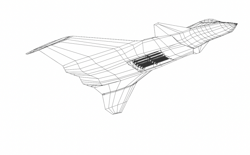
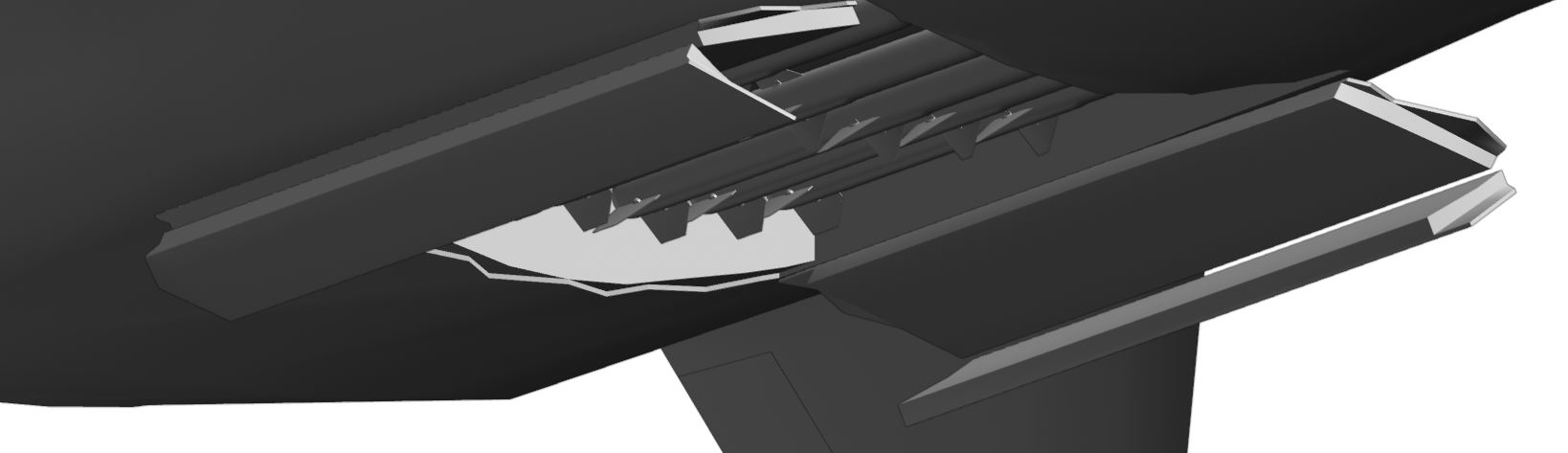
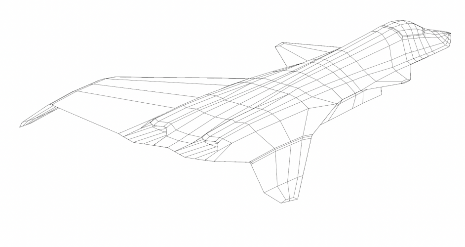
There is a chance it could get away with this, kind of F-22 gear but flipped across the longitudinal axisI've had a lot of people reach out to me for this, and other stuff too, seems people like the model, which is cool. I've spent the last few days making a larger variant; the one shown is too small to meet range requirements for a US variant but would be perfect for a European variant. Larger variant attached; I also redid the nozzles and a good amount of the empennage to fit a model I made of the XA103 more accurately. I'm not sure how to handle the gear and am working on that now. There doesn't seem to be quite enough room to do F-22 style, since the engines are further apart here. Either will have to go F-35-style (maybe even retracting backwards), or somehow get them to go between the engines, not sure how that would work.
Attachments
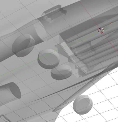
There is a chance it could get away with this, kind of F-22 gear but flipped across the longitudinal axis
Attachments
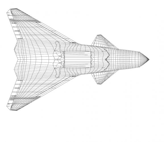
donnage99
ACCESS: Top Secret
- Joined
- 16 June 2008
- Messages
- 1,586
- Reaction score
- 1,640
I got what you’re saying the first time. When I said “changing of lift force” it doesnt imply mean there’s significant downward forceThat is incorrect.
The vast majority of the wing structural loads is an upwards force. With the traditional wing fold mechanism if the locking mechanism failed the wing tip can fold upwards as that is the direction it usually folds.
With this wing mechanism if the locking mechanism failed the wing tip can't go further upwards as the wing pivot joint would not allow it. The wing pivot only allows it to fold downwards.
The locking mechanism on the F-47 would only need to handle downward forces. These are a tiny fraction of the load. Aircraft only get a high angle of attack in the positive direction. They do not get a negative angle of attack that would cause a downward force on the wing.
The only downward forces on the wing would be from rolling and this would be a single digit percentage of the upwards load when at a high angle of attack.
The downward folding mechanism could probably be 10-20% of the weight of the upwards folding mechanism.
insidersource
ACCESS: Top Secret
- Joined
- 24 March 2025
- Messages
- 521
- Reaction score
- 745
It retracts backwards. The landing gear doors are open in the night vision video. They are clearly to the rear. Here's the Boeing MQ-28.Either will have to go F-35-style (maybe even retracting backwards), or somehow get them to go between the engines, not sure how that would work.
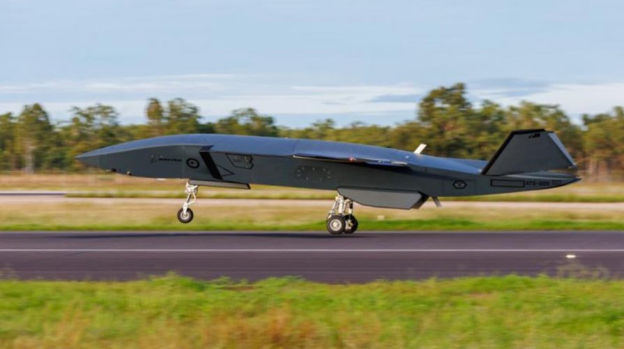
The night vision video suggests the landing gear doors are about 50% longer than the MQ-28 relative to the aircraft length. A taller gear is required due to the downward tips being at the back of aircraft.
The F-22, F-35 and Su-57 all have bulges due to how their landing gear retracts. The F-47 being a delta wing the thickest part of the wing is aft of the landing gear. Retracting to the rear is obviously the best solution. There is a nice empty space beside each engine.
- Joined
- 6 August 2007
- Messages
- 4,539
- Reaction score
- 10,259
The F-47 being a delta wing the thickest part of the wing is aft of the landing gear.
Do you have a photo of this “F-47 delta wing”?

Rbyn512
ACCESS: Restricted
- Joined
- 6 April 2024
- Messages
- 5
- Reaction score
- 2
Where'd you get this from?Also consider the Boeing demonstrator was designed for the Navy
- Joined
- 27 December 2005
- Messages
- 19,230
- Reaction score
- 35,692
He pulled it out of his ass, just like every other post he ever made.
@insidersource is banned from the forum for being an insufferable troll.
@insidersource is banned from the forum for being an insufferable troll.
Last edited:

Hull down
ACCESS: Confidential
- Joined
- 19 February 2023
- Messages
- 196
- Reaction score
- 519
surreal to finally see it happen lolHe pulled it out of his ass, just like every other post he ever made.
@insidersource is banned from the forum for being an insufferable troll.

FlyGuy369
Flying is fantastic
- Joined
- 15 June 2023
- Messages
- 578
- Reaction score
- 1,699
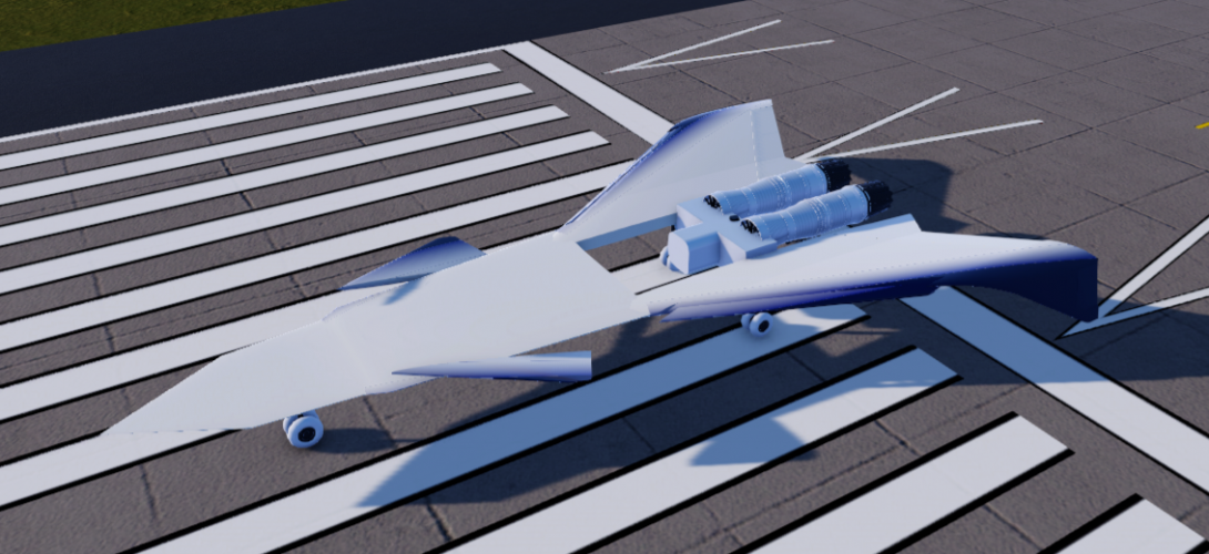
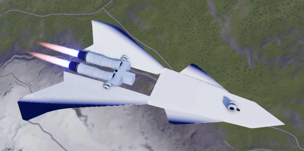
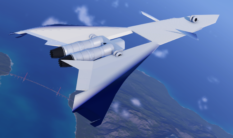
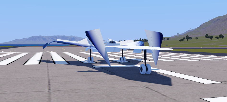
Okay update time:
Been grinding really hard at this for some time. It is a large aircraft, around 70ft, engine spec is 110K lbs thrust w/ab. Had to pay my homage to the X-36 with the paint job! Got all of the control laws finally dialed in from what materials and resources I could study. Everything from canard function to X-36 flight test footage. This is just a very basic model with more to come!
Been grinding really hard at this for some time. It is a large aircraft, around 70ft, engine spec is 110K lbs thrust w/ab. Had to pay my homage to the X-36 with the paint job! Got all of the control laws finally dialed in from what materials and resources I could study. Everything from canard function to X-36 flight test footage. This is just a very basic model with more to come!
Attachments



Low IQ Techie
Low IQ, mid-aged, IT Engineer, Military enthusiast
- Joined
- 4 December 2022
- Messages
- 295
- Reaction score
- 634
Reddington777
ACCESS: Top Secret
- Joined
- 23 March 2025
- Messages
- 848
- Reaction score
- 2,800
End of an era.He pulled it out of his ass, just like every other post he ever made.
@insidersource is banned from the forum for being an insufferable troll.
It was like watching divest being banned from r/noncredibledefense.
- Joined
- 27 December 2005
- Messages
- 19,230
- Reaction score
- 35,692
He wasn't generally breaking rules as such, just....
Scott Kenny
ACCESS: USAP
- Joined
- 15 May 2023
- Messages
- 19,654
- Reaction score
- 28,133
Talking out of his ass more than I do.He wasn't generally breaking rules as such, just....
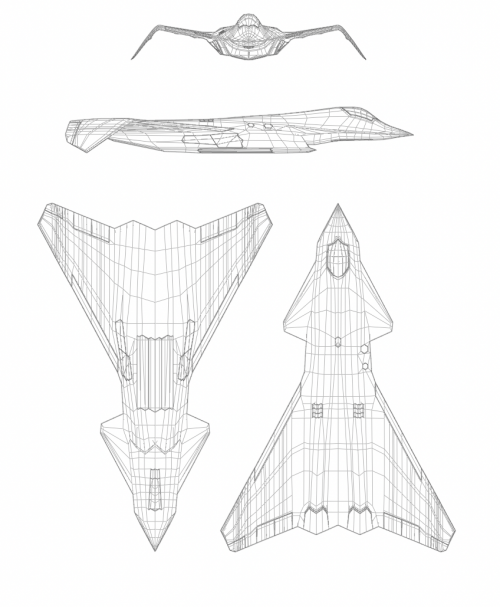
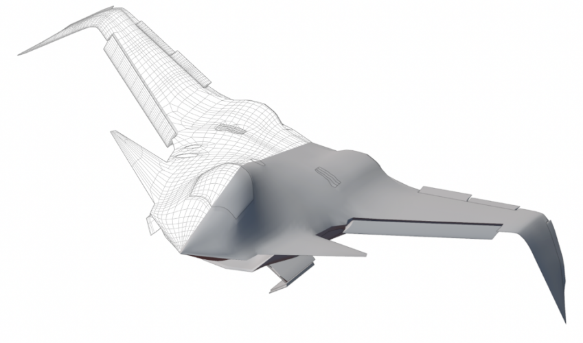
did a lot of work over the last few days, using the two published images, among many many other constraints, im now significantly more confident in this design. aligns basically perfectly with both the renders, and the infrared video as well
Attachments
whats the stuff on the canopy?Quick edit of F-22
- Joined
- 27 December 2005
- Messages
- 19,230
- Reaction score
- 35,692
Rainbow sparkles.whats the stuff on the canopy?
Low IQ Techie
Low IQ, mid-aged, IT Engineer, Military enthusiast
- Joined
- 4 December 2022
- Messages
- 295
- Reaction score
- 634
The original artist uses those marks to depict large glass surface like canopy.whats the stuff on the canopy?
I love the "Revenge of the X-32" vibes it gives.did a lot of work over the last few days, using the two published images, among many many other constraints, im now significantly more confident in this design. aligns basically perfectly with both the renders, and the infrared video as well
Similar threads
-
 CGI - Attempted reconstruction of ProjectFear possible Boeing AII-X demonstrator
- Started by CiTrus90
- Replies: 58
-

-
 Planes of the Future: Boeing's 1950 jet-transport designs
- Started by overscan (PaulMM)
- Replies: 1
-

-
 Boeing F-47 NGAD - Speculation and Theories
- Started by Bounce
- Replies: 2K