Canadair's VTOL projects before the CL-84

hesham

ACCESS: USAP
Senior Member
Joined
26 May 2006
Messages
32,498
Reaction score
11,588
The canadair CL-84 was a twin engined tilt-wing V/STOL research aircraft,
there were a series of experimental designs produced before and led to it;
that included the CL-43 in 1953,followed by the CL-73 and CL-74
reconnaissance aircraft, but the company felt it can produced a bigger type
to be better, so it designed the CL-62 which could be built with two,four
or eight engines and would weight in at around 53.000 lbs,
the CL-62 led to CL-84.
 
Does anyone have any details on either the Orenda PS-16 engine or its installation in the proposed Canadair CL-72 -- the 1958 VTOL strike/reconnaissance aircraft concept.

Avroland (http://www.avroland.ca/al-collection.html) mentions an article entitled "Orenda VTOL" in the March 1961 copy of Aircraft Magazine. By chance, does anyone have access to this now-defunct Canadian periodical edited by Bob Halford?

Any info or suggestions for search approaches much appreciated.
 
Hi all,

found this pics from the initial Canadair CL-84...
 

Attachments

  • Canadair CL-84.jpg
    Canadair CL-84.jpg
    257.6 KB · Views: 346
  • Canadair CL-84-1.jpg
    Canadair CL-84-1.jpg
    91.8 KB · Views: 318
...and from the Canadair CL-74 with two GE T.58-GE-3...
 

Attachments

  • Canadair CL-74.jpg
    Canadair CL-74.jpg
    84.1 KB · Views: 302
  • Canadair CL-74-1.jpg
    Canadair CL-74-1.jpg
    87.6 KB · Views: 302
...hesham you speak about the Canadair CL-43. Please, the twin engine military logistics support aircraft.
Powered by two P&W with 600HP.
 

Attachments

  • Canadair CL-43.jpg
    Canadair CL-43.jpg
    168.4 KB · Views: 289
...if you have drawings from the CL.62 and CL.73 please post them.

Enjoy and thanks Maveric
 
Thanks for this post of the Canadair CL-43, unknown twin-boom project of 1953.
Does someone confirm it has a rear door and fixed landing gear?
 
Tophe,

As far as I know the reardoors were of clamshell design.
Besides the fixed undercarriage type, variants with
skies and floats were also proposed.
 
...equipped with double slotted flaps and automatic leading edge slats. The twin boom configuration was of simple structural design, and the aircraft could take off over a fifty-foot obstacle in just 850 feet.

Servus Maveric
 
From 'Air Enthusiast' No.68, March/April 1997, pp. 66-9 :-

"The CL-43 of 1954...
this 'logistics supply model having a twin-boom
configuration to permit direct loading through twin
rear doors. The high-wing CL-43 powered by two
P&W R-1340 pistons(sic)...
to have been offered in floatplane and ski versions
as well as the basic tailwheel undercarriage design...
the CL-204 floatplane, studied in 1962, but based on
the CL-43 military(?) transport proposed in 1954...

...a proposal to build the CL-74 army reconnaissance
aircraft powered by two Allison T63-A-3 turboprops...


cheers,
Robin.
 

Attachments

  • canadair CL-74.jpg
    canadair CL-74.jpg
    315.5 KB · Views: 90
  • canadair CL-204.jpg
    canadair CL-204.jpg
    405.7 KB · Views: 75
kagemusha said:

index.php


NOTE: this topic is made up of excerpts from that document, previously shared by forum member Kagemusha in the CL-84 topic, and entitled:
DESIGN AND DEVELOPMENT HISTORY OF THE CANADAIR CL-84 V/STOL TILT-WING AIRCRAFT (written by Bill Upton, Canada Aviation Museum Research Volunteer, and published by the Canada Aviation Museum).


Preliminary Canadair V/STOL Research and Design

Early in the 1950s, a dynamic engineering research team at Canadair Limited, led by chief of Aerodynamics and Design, Frederick C. Phillips, and Latvian-born mechanical design engineer Karlis Irbitis, examined some preliminary designs for various VTOL and STOL aircraft configurations. These initial design conceptions included a few stillborn proposals, such as a lightweight VTOL two-seater, with a tiltable two-bladed rotor on a pivoting boom that protruded through the cockpit canopy. The rotor system was driven by compressed air jets at the blade tips, fed by a hub mounted radial compressor driven from a 200 hp Turbomeca Artouste turboshaft engine.

Alternatively, a twin-engine tail-sitter VTOL concept, somewhat resembling the Chance Vought V-173 “Flying Pancake” of the early 1940s, was sketched out, seen to incorporate a hinged cockpit section that was positioned parallel to the ground for takeoff and landing, then rotated inline to the fuselage once inflight.
Two versions of the cockpit arrangement were proposed, one having the pilot in a standard seated position, the other with the pilot operating the aircraft from a prone position. Both the United States and Britain had conducted practical prone piloting research in the immediate post-war years, using specially modified aircraft, with less than satisfactory results.

Another radical VTOL scheme, this one for a “Convertible Transsonic Aeroplane”, was drawn by Irbitis in late 1952. This tail-sitter aircraft, akin to Convair’s Pogo, was a most complex arrangement, incorporating delta-wing, swing-wing, rotary-wing, and swept-wing technology all in one design. The basic layout was a
tall, cruciform delta stationary wing, with large vertical and ventral fins married around a powerful turbojet engine. Above was a dual rotary wing arrangement incorporating ramjets at the tips, then the cockpit fronted with an oval-shaped air intake. For takeoff, the rotary wings were spread horizontally, the main engine, once started also supplied compressed air to the ramjets, and the rotary wings revolved. Conversion to conventional flight involved stopping the ramjets, locking the rotary-wing at an angle of 90-degrees and sweeping them back flush with the stationary wing body thus becoming a delta-wing aircraft.

In 1954, Irbitis was tasked with examining and completing a review of all known principals of lift and thrust creating systems, and their application to V/STOL aircraft design. Phillips applied his extensive knowledge and experience in VTOL aircraft gleaned from his previous years of research and design on the technologically innovative McDonnell Aircraft XV-1 convertiplane programme. Phillips had joined Canadair as the head of the Aerodynamics and Preliminary Design Departments, and would earn a place of renown when he led an engineering team in designing the first wholly in-house production aircraft, the jet-powered CL-41 Tutor trainer. Now he was embarking on the second Canadair in-house design endeavor, becoming the Programme Manager of a truly radical venture that was hoped to be able to match the success achieved with his earlier effort.

In May 1956, Phillips and Irbitis combined their accumulated expertise in a formal paper entitled “Lift and Thrust Creating Systems and Their Application to V/STOL Aircraft Design”, presented at the annual general meeting of the Canadian Aeronautical Institute in Montreal. This, and a follow-on paper by this team to the Defence Research Board (DRB), “VTOL Transport Configuration Studies”, became the genesis of theoretical and applied studies into V/STOL aircraft technology at Canadair.
 

Attachments

  • Canadair’s Karlis Irbitis and Frederick C. Phillips.jpg
    Canadair’s Karlis Irbitis and Frederick C. Phillips.jpg
    18.7 KB · Views: 367
CL-45 VTOL

[This project was actually a helicopter and it is covered in a separate topic, which can be found here:
https://www.secretprojects.co.uk/forum/index.php/topic,28616.0]
 
Very nice,but

we have this report before in reply # 65 at this topic,and I sent most of its drawings;

https://www.secretprojects.co.uk/forum/index.php/topic,4267.msg300356.html#msg300356

Also;

https://www.secretprojects.co.uk/forum/index.php/topic,28616.msg300425.html#msg300425
 
hesham said:
Very nice,but we have this report before in reply # 65 at this topic,and I sent most of its drawings;
https://www.secretprojects.co.uk/forum/index.php/topic,4267.msg300356.html#msg300356
https://www.secretprojects.co.uk/forum/index.php/topic,28616.msg300425.html#msg300425

Oh, okay, sorry. Only came across this document recently. I had overlooked your posts because to me these were not "CL-84 projects", as the title of the topic implied. Beside, neither the previous PDF link nor the extracted images provided any relevant keywords for the forum's search engine, which is why my initial search on "CL-43" or "CL-62" provided no results and I ended up unwittingly reposting the document.
Also I think there is a difference I think between simply sharing strings of pictures and trying to add some informative writeout to document them (even if in this case I didn't write it myself).
 
Canadair CL-62 V/STOL Series Phase 1

From 1956 to 1959, at the instigation of the Canadian DRB, and with support from the Canadian Department of Defence Production (DDP), Canadair conducted initial design studies of various logistic transport vehicle configurations suitable for providing supplies to Army units in a dispersed battlefield environment.

The US Army Study Requirements ASR3-60, for V/STOL transport specifications, called for an aircraft capable of transporting a 2,268 kg (5,000 lb) payload over a mission radius of 402 km (250 miles), with a total hovering time of 9 minutes. Canadair was awarded a contract worth $30,000 on 14 February 1958, towards a design study of several VTOL aircraft configurations employing different arrangements of achieving VTOL lift, per the Army requirements.

By mid-1958, an initial cadre of five relatively heavyweight designs for V/STOL aircraft emerged from the Canadair design offices, with additional VTOL research and support being provided by the National Research Council (NRC) in Ottawa. Comparative studies were conducted on these Phase 1 CL-62 designated model concepts, with each one exploiting a unique design philosophy incorporating most of the perceived modes of achieving the optimum method to accomplish the proposed mission objectives.

To facilitate the design process, the CL-62-1 through CL-62-4 model configurations, conceived for low altitude operations, employed a common multi-glassed cockpit, squared cross sectional cargo box, clamshell cargo door arrangements, and empennage. A dorsal extension covered the routing of the tail rotor drive shaft assembly. To ensure adequate propeller ground clearance, along with a convenient cargo floor height, a high wing arrangement was chosen, the height of which was basically determined by the propeller diameter, and the span by the need to have the slipstream pass over the entire wing to optimize V/STOL operations.

The CL-62-5 model, incorporating turbojet propulsion, was designed to operate efficiently at a cruising altitude of 13,716 m (45,000 ft), and therefore was to be pressurized, consequently it was not feasible for it to have the common square cross-sectional fuselage design of the other four concepts. Also, due to the relatively high placement of the cargo floor, it would appear difficult to load and unload, or airdrop cargo, without compromising the rear pressure bulkhead. To minimize jet blast upon the sides of the fuselage, a low wing placement and high landing gear design was chosen.

[CL-62 variants detailed in subsequent posts]
 

Attachments

  • CL-62 Phase 1.png
    CL-62 Phase 1.png
    130.6 KB · Views: 129
  • CL-62 Phase 1 chart.png
    CL-62 Phase 1 chart.png
    222.4 KB · Views: 115
CL-62-1 Slipstream Deflection

This basically STOL variant had the slipstream that developed from the large diameter propellers, along with the engine exhaust, deflected along the wing and vertically downwards by a large, powerful trailing edge flap system, with lift in the transition being provided by the resulting reaction. With all flaps retracted, conventional horizontal flight would be achieved.

CL-62-1 Specifications:
Generally, the high-wing design was of a conventional rectangular-shaped planform, with multiple section full-span extendible flaps, mounted atop the constant 2.5 m (8.3 ft) square cross section fuselage. Atop the cabin was a large mid-fuselage to vertical tail dorsal fin extension. A very sizeable amount of cockpit glazing, for improved crew visibility downwards and to the sides, was incorporated. Large, upward curving clamshell cargo loading doors were at the rear of the 7.6 m (25.0 ft) long cargo hold area.

A set of tall tricycle type, dual paired low-pressure nose and main gear tires, were to be incorporated as standard, with the main gear retracting forward into large fuselage side pods. A retractable, single wheel outrigger gear was mounted to the bottom of each of the outboard engine nacelles. A fixed tail skid was provided, such that the aircraft could be tilted back on its main gear, and with the wing’s full flaps deployed to a 20-degree angle-of-attack orientation, would thereby allow the aircraft to effect a short, near vertical take-off when runway space was at a minimum.
The aircraft was to have a gross weight of 14,946 kg (32,950 lbs), had an overall length of 17.5 m (57.5 ft), height of 7.8 m (25.5 ft), and a wingspan of 23.4 m (76.7 ft).

Four 2,500-horsepower Lycoming T55 turboshaft engines drove four, 3-bladed, 4.7 m (15.5 ft) diameter wide chord propellers, so arranged as to completely bathe the entire wing in the resultant slipstream. A single, 2-bladed, 3.0 m (9.8 ft) diameter tail rotor, mounted atop the cruciform tail configuration, provided longitudinal pitch control in the transition and low-speed portions of flight.


CL-62-2 Tilting Wing

The tilting wing concept had the engines providing not only propulsion for forward flight, but also supplying lift for VTOL operations, when the wing and nacelles were rotated into vertical position via a dual hydraulic screw jacks system at the tilt axis pivot point. The propellers would act in the manner of rotors for VTOL operations.

A unique and difficult phase of flight occurs when the aircraft has to transition from the vertical to level flight, and the propellers cease to act as rotary wings before the wing is actually working to keep the aircraft in the air. Controlling the pitching moments of the aircraft during transition was a problem typical for tilt-wing and deflected slipstream types of machines. The most efficient application of cyclic pitch control was deemed to result if a tail rotor system were called upon to provide some of the lift during the hover and transition phases. By the correct programming of the wing flaps, the pitch moments would be effectively reduced to zero by a positive upload on the tail rotor, the configuration also aiding in minimizing wing stalling.

CL-62-2 Specifications:
The 2.5 m (8.3 ft) square, box-like sectional fuselage had a generous amount of cockpit glazing for sufficient visibility downwards and to the sides. At the aft end were large, clamshell type cargo loading doors, providing access to the 7.6 m (25.0 ft) long cargo hold. The top mounted tilting wing, with 71.25 m² (767.0 ft²) of area, had swept forward and leading edges, with full span leading and trailing edge flaps to eliminate difficult handling problems, and provide ample control margin in the transition regime.

Low pressure, dual nose gear, and tandem main gear tires were to be supplied as standard. The squat, C-130 Hercules style main gear, retracted upwards into fuselage side sponsons. A retractable, single wheel outrigger gear was mounted to each outboard wing tip, lying flush under the wing during flight.
The aircraft was to have a gross weight of 13,703 kg (30,210 lb), an overall length of 16.0 m (52.5 ft), height of 7.3 m (24.0 ft), and a wingspan of 23.4 m (76.7 ft).

Four 2,000-horsepower Lycoming T55 turboshaft engines, interconnected with cross shafting for additional engine out safety, driving four, 3-bladed, 4.7 m (15.5 ft) diameter propellers, provided the thrust for level and VTOL flight operations.

Alternatively, as the CL-62-2A concept, eight General Electric T58-GE-2A gas turbine engines, arranged in a configuration of four pairs coupled within nacelles under the wing, would provide power. The two engines within each nacelle would be connected to a single propeller by overrunning clutches and gearbox array. A single, 2-bladed, 3.0 m (9.8 ft) diameter tail rotor mounted atop the vertical fin provided longitudinal pitch control in the transition and hover portions of flight.


Photo caption: With a commonality of the basic fuselage design, a 1/7-scale model representing the mean configuration of the CL-62-1 and CL-62-2 airplanes was built in 1958, for aerodynamic testing on the Mobile VTOL Test Rig.
 

Attachments

  • CL-62 test rig model.jpg
    CL-62 test rig model.jpg
    46 KB · Views: 102
  • CL-62-2 & -2A (modified drawing by Bill Upton).png
    CL-62-2 & -2A (modified drawing by Bill Upton).png
    88.9 KB · Views: 105
  • CL-62-1 (modified drawing by Bill Upton).png
    CL-62-1 (modified drawing by Bill Upton).png
    85.1 KB · Views: 105
CL-62-3 Tilting Ducted Fan

The tilt duct propulsion concept consisting of cross shafted, tilting, ducted propellers had several virtues in that the ducts augmented the propeller thrust and worked as additional wing surface area during takeoff and conventional wingborne flight. Deflector vanes inside the ducts provided precise thrust and trim control in the transition and hover, and any propeller turbulence was kept away from wing and tail control surfaces. Precise control positioning of the ducted fans while rotating between the vertical and horizontal was to be performed aerodynamically via moveable duct ailerons located at the top and bottom aft edges of the ducts.

CL-62-3 Specifications:
The fuselage was also 2.5 m (8.3 ft) square boxed-shaped, with liberal glazing around the cockpit affording excellent visibility to the crew during all aspects of flight. A sweep trailing edge wing design was shoulder-mounted, with 4.6 m (15.0 ft) diameter propeller ducts mounted outboard, pivoting together at the 25% mean aerodynamic chord. A bumper was affixed to the bottom side of each duct. Low pressure paired dual nose gear and tandem main gear tires were standard, with the squat main gear retracting upwards into fuselage side sponsons.
This variant had a proposed gross weight of 13,753 kg (30,319 lb), a length of 16.6 m (54.6 ft), height to the top of the tail rotor was 7.1 m (23.3 ft), and it had an overall wingspan, inclusive of the propeller ducts, of 23.4 m (76.7 ft).

Four 2,500-horsepower Lycoming T55 turboshaft engines, mounted in side by side podded pairs atop the fuselage at the wing juncture, were to power the two, 8-bladed, 3.9 m (13.0 ft) diameter interconnected ducted propellers via long shafts within the wings. A single, 2-bladed, 3.0 m (9.8 ft) diameter tail rotor was to be mounted atop the vertical fin to provide longitudinal pitch control.
 

Attachments

  • CL-62-3 (modified drawing by Bill Upton).png
    CL-62-3 (modified drawing by Bill Upton).png
    81.7 KB · Views: 61
CL-62-4 Jet Lift Turboprop

This concept envisioned a dual propulsion type engine configuration that had a series of small lightweight lift-jets aligned along each side of the fuselage providing thrust mainly for the V/STOL mode. Dual standard arrangement of wing mounted turboprop engines would provide the propulsion for conventional flight.

CL-62-4 Specifications:
This squat transport variant incorporated a high wing design with 71.25 m² (767.0 ft²) of area married to a 2.5 m (8.3 ft) square-shaped fuselage with a generously windowed cockpit. The 7.6 m (25.0 ft) long cargo hold incorporated large clamshell type cargo doors at the rear. A fuselage to tail dorsal fin extension terminated halfway up the cruciform type empennage. Unique full fuselage length side blisters contained the lift-jets arrangement, with the jet exhaust expelled downwards and angled slightly outboard and to the rear. Low pressure paired dual nose gear, and tandem main gear tires were standard, with the mains retracting straight upwards into the central section of the side blisters.
This model had a projected length of 16.0 m (52.5 ft), height to the top of the tail of 6.6 m (21.6 ft), a 23.4 m (76.7 ft) wingspan, and was to weigh in at 14,579 kg (32,140 lb).

Two 1,850-horsepower Lycoming T55 turboshaft engines, driving 3-bladed, 3.5 m (11.5 ft) diameter propellers for conventional flight, were to be augmented by the addition of sixteen 10.9 kN (2,450 lbf) thrust each General Electric J85-GE-5 turbojet engines for V/STOL operations. The turbojet engines in the fuselage side fairings were installed aligned in an arrangement of four-forward, and four-aft, of the main landing gear. Atop the fairings were rectangular-shaped intake covers and guide vanes, with the engine exhaust covers and directional control vanes below. Each engine had an inspection access door on the exterior flat-faced side of the fairings. The extreme noise levels produced by such an aircraft would have been intolerable at best to anyone in the vicinity of operations, an annoying aspect common to all jet VTOL aircraft. Additionally, the exhaust temperatures associated with sixteen operating jet engines in VTOL mode upon the ground surface, and the potential of hot air recirculation onto the fuselage and landing gear would certainly pose a potentially serious problem. Utilizing this aircraft on unprepared sites would be critically limited.
 

Attachments

  • CL-62-4 (modified drawing by Bill Upton).png
    CL-62-4 (modified drawing by Bill Upton).png
    71.4 KB · Views: 58
CL-62-5 Turbojet-Lift Propulsive Wing

A rather unique design concept, wherein all of the propulsive engines, seven per wing, are mounted axially within the wings, thereby permitting undisturbed aerodynamic flow over the wings due to lack of protrusions. The exhaust from the series of engines was to be expelled onto full trailing edge plug ailerons, which would act as nozzles to deflect the thrust for vertical and conventional flight regimes.

CL-62-5 Specifications:
A fairly large jet aircraft for its type which differed appreciably from the other designs, the two-man flight crew sat side-by-side under an enclosed Vulcan bomber style bubble canopy atop the forward area of the pressurized, circular cross sectional fuselage. Visibility would be hampered, compared with all of the other contenders, by the need to minimize cockpit transparencies in the pressurized fuselage.

It was to have a gross weight of 16,130 kg (35,560 lb), a length of 22.6 m (74.2 ft), a main fuselage diameter of 3.0 m (10.0 ft), that tapered roundly at the forward end, and more pointedly aft at the conventional style empennage. An overall height of 7.2 m (23.5 ft) was projected. The wing, with a comparatively small 50.2 m² (540.0 ft²) of area, had a span, inclusive of the wingtip fuel tanks, of 13.7 m (45.0 ft). The wing size was determined by the size of the small turbojets installed within the aft portion.

Unique, stalky, dual nose and main caterpillar-type track system undercarriage, were to be employed to permit operations on unprepared areas and to distribute the aircraft footprint when carrying heavy cargo loads to smaller airfields and unimproved strips.

A series of fourteen 10.9 kN (2,450 lbf) thrust General Electric J85-GE-5 turbojet engines, contained within the aft rotating portion of the wings, with full span air intakes at the leading edge, would have provided high altitude cruise propulsion economically, by utilizing only eight of the fourteen engines.

Each wing, with a rotating exhaust deflector, would provide VTOL lift by diverting all of the engines and associated exhaust downwards. Fixed outrigger shock struts would be deployed from the wing/fuel tank juncture prior to landing. Three side-by-side aligned General Electric J85 control engines deployed vertically downwards from an enclosure immediately aft of the nose gear door to provide longitudinal pitch stabilization for the transition, hover and VTOL lift portions of flight. However, precise control with the nose jets seemed doubtful due to the long spool-up time required for these early jet engines compared with almost immediate response when using rotor-type pitch stabilization systems.

Drag reducing fairings on the sides of the fuselage, forward and aft of the wings, produced a somewhat area ruled shape, but the savings potentially gained in aerodynamics would have been offset by the huge fuel consumption from the engines. With all of the propulsive jets mounted within the straight wings and forward fuselage, and associated fuel carried in the large wing-tip type pods, much needed space in the fuselage was available for cargo, the area accessed via dual rear clamshell-type doors and a relatively steep loading ramp.

As with the CL-62-4 concept, the high velocity hot exhaust recirculation impinging upon the bottom of the fuselage and landing gear units could have posed serious problems, and would also have made the use of unprepared sites for VTOL operations impractical.
 

Attachments

  • CL-62-5 (modified drawing by Bill Upton).png
    CL-62-5 (modified drawing by Bill Upton).png
    64 KB · Views: 57
CL-62-6 Large Tilt-Wing

This basic 4-engine tilt-wing aircraft was designed in December 1959, also as part of the ASR3-60 specifications, following a later decision to proceed with further studies of a larger tilt-wing aircraft beyond the previous Phase 1 concepts. It was tailored for the primary mission of a V/STOL logistic transport, and with a secondary mission of VTOL tactical airlift, capable of supplanting both the Caribou transport and Chinook helicopter, then in service. Distinct advantages of the tilt-wing concept for these missions included the immediate choice of zero, short, or conventional length takeoffs and landings to match terrain and/or load conditions, and zero or slow speed flight for search/rescue, cargo pickup and dropping.

CL-62-6 Specifications:
This transport design incorporated a more conventional style cockpit window layout than those seen previously in the five Phase 1 conceptions.

The 19.4 m (63.8 ft) long, 2.4 m (8.0 ft) wide fuselage incorporated a 7.6 m (25.0 ft) long cargo compartment, accessed by large clamshell cargo doors at the 8.1 m (26.4 ft) high, upswept tail. The cargo compartment could also accommodate up to 32 fully equipped troops seated in 8 rows. The rectangular, high-wing planform had a span of 20.2 m (66.3 ft), with full-span, segmented trailing edge flaps, and outboard spoilers. Wing tilt was accomplished by means of dual hydraulic screw jack assemblies, located on each side of the upper fuselage, behind the cockpit. The all-moving horizontal-stab rotation was coordinated with the selected wing tilt. Low pressure paired dual nose gear, and tandem main gear tires were incorporated. The latter, being retraced into small fuselage side sponsons. This aircraft was to have a gross takeoff weight of 16,012 kg (35,300 lb) in VTOL, 18,734 kg (41,300 lb) in STOL, and up to 18,960 kg (41,800 lb) in the Ferrying roles.

Four 2,650 shaft-horsepower General Electric T64-GE-2 turbo-shaft engines, were to drive four, 4-bladed, 4.9 m (16.0 ft) diameter LH and RH controllable pitch propeller sets. A single down-facing 2.2 m (7.2 ft) diameter, 4-bladed tail rotor was to provide longitudinal pitch control in the transition and hover.
 

Attachments

  • CL-62-6.png
    CL-62-6.png
    73.1 KB · Views: 59
Canadair CL-62 Series Phase 2

The results of the CL-62 Phase 1 design models were compiled in the paper called “VTOL Transport Configuration Studies”, and were presented at a Canadian Aeronautical Institute meeting in 1958. The conclusions to the tradeoff studies indicated that the deflected slipstream and tilt-wing types were preferable for the given requirements, although it was recognized that the former was inefficient in the hover, and the latter had undesirable transition characteristics. This resulted in a decision that a combination of these two principles would avoid these disadvantages and yield the optimum arrangement. This presented a vehicle with a variety of potential military and civil applications as a result of performance and flexibility in both the vertical and short takeoff and landing regimes. From the generalized configuration identified by these studies, it was decided to proceed with the design and development of practical research vehicles, and test hardware to validate the conceptual principles, and to develop the necessary technology, a somewhat bold new step for Canadair.

In 1959, Canadair undertook CL-62 Phase 2 research and advanced development design studies towards optimizing a definitive tilt-wing/deflected slipstream configuration, against the requirement for an Army logistic VTOL Transport, specified and partly funded by the Canadian DRB. What resulted included two new model designs of the CL-62 (A and B) that warranted general aerodynamic studies on problems associated with tilt-wing aircraft, and to assess the differences in characteristics between two- and fourpropeller aircraft configurations to the same given specification. At this same time, a funded Phase 3 study involved the design, construction and development of a Mobile Test Rig for aerodynamic tests on actual tilt-wing VTOL scaled models.

[CL-62 Phase 2 projects will be detailed in posts below]
 

Attachments

  • CL-62A & -62B.png
    CL-62A & -62B.png
    146.8 KB · Views: 54
CL-62A Tilt-Wing/Deflected Slipstream

The CL-62A tilt-wing/deflected slipstream V/STOL aircraft was conceived as a four-engine, small four-propeller design. A more conventional cockpit window arrangement included large framing, and the addition of a downward view window on each side.

CL-62A Specifications:
The 19.4 m (63.5 ft) long rectangular cross-sectional fuselage contained a cargo compartment that was 2.4 m (8.0 ft) wide, 2.0 m (6.5 ft) high and 8.5 m (28.0 ft) long, and incorporated rear clam-shell type doors to permit direct loading from truck bed height onto the floor. The aircraft could accommodate up to 7,258 kg (16,000 lb) of cargo, or up to 32 fully equipped troops along with a flight crew of two.

The design VTO weight was set at 18,144 kg (40,000 lb), permitting a payload mission radius of approximately 833 km (450 nm). The aircraft’s STO weight capability was up to 21,773 kg (48,000 lb), with a payload mission radius of approximately 1,341 km (725 nm). These were based on a sea level cruising speed of 250 knots (463 km/h / 287 mph) with fuel allowances for up to 10 minutes of hover. At the STOL weight, the ferry range was 5,458 km (2,950 nm) at 340 knots (630 km/h / 391 mph).

The rectangular planform wing had a span of 21.7 m (71.1 ft), with an area of 73 9 m² (796 ft²), and incorporated full span leading and trailing edge flaps. STOL performance of the CL-62A was to be superior to that of the CL-62B design by virtue of its larger wing span and lower wing loading. Wing tilt angles from 0 to 90 degrees was accomplished by means of dual hydraulically driven screw jack assemblies located on each side of the upper fuselage. The dual nose and main tricycle-type landing gear had low pressure tires, with the main units retracting forward into fuselage side sponsons and the nose gear retracting aft into the fuselage.

Four 2,650 shaft-horsepower, General Electric T64-GE-2 turbo-shaft engines were to drive four shaft interconnected, 4-bladed, 5.0 m (16.3 ft) diameter propellers. The multiple propeller interconnection system ensured full controllability of the aircraft in the event of an engine failure.

Beneath the 8.2 m (26.8 ft) tall empennage was a single, down-facing 2.2m (7.2 ft) diameter, 4-bladed tail rotor, to provide longitudinal pitch control.
 

Attachments

  • CL-62A.png
    CL-62A.png
    72.7 KB · Views: 46
CL-62B Tilt-Wing/Deflected Slipstream

The CL-62B tilt-wing/deflected slipstream design, in almost all-physical respects similar to the CL-62A model, was a four-engine, large two-propeller design to assess performance characteristic differences with the CL-62A.

CL-62B Specifications:
The proposed design VTO weight of 18,144 kg (40,000 lb) permitted a payload mission radius of approximately 971 km (525 nm). The aircraft’s STO weight capability at 21,773 kg (48,000 lb) enabled a payload mission radius of approximately 1,434 km (775 nm). These were based on a sea level cruising speed of 250 knots (463 km/h / 287 mph) with fuel allowances for up to 10 minutes of hover. At the STOL weight, the ferry range was 5,180 km (2,800 nm) at a speed of 344 knots (636 km/h / 395 mph). The empty weight of the CL-62B was estimated at 590 kg (1,300 lb) less than that of the CL-62A.

The rectangular planform, 16.3 m (53.6 ft) span wing, with a total area of 55.7 m² (600 ft²), incorporated full span leading and trailing edge flaps. Because of the lower drag and weight of the smaller wing, the CL-62B had a better payload-mission radius capability compared to the CL-62A.

Four 2,650 shaft-horsepower, General Electric T64-GE-2 turbo-shaft engines, in a two pairs coupled configuration, were to drive four shaft interconnected, 4-bladed, 6.9 m (22.6 ft) diameter propellers. The large propeller diameter was selected to give a disk loading essentially equal to that of the CL-62A, and would provide the same performance, stability and control in the transition. As a result of the large propeller diameter, it was deemed necessary during ground operations to maintain a minimum of 15 degrees of wing tilt to provide adequate ground clearance during ground operations.

Another offshoot scheme proposed was the CL-62B-2 model, designed for the V/STOL logistic transport role, with the aircraft modified as necessary for use aboard aircraft carriers.
 

Attachments

  • CL-62B.png
    CL-62B.png
    75.1 KB · Views: 55
Canadair-McDonnell Model 175

During April 1961, in conjunction with the McDonnell Aircraft Corporation, Canadair submitted a highly detailed proposal to the US military towards the US Tri-Service V/STOL Transport Aircraft competition as per Specification TS-152. Other similar paper design entries were made by the likes of aircraft manufacturing giants Grumman, Boeing, Chance Vought, Bell and North American Aviation. Some of the contenders that eventually advanced to the flying hardware stage in this competition included the Curtiss-Wright X-19 tilted-propeller design, the Bell Model X-22A ducted-fan configuration aircraft, and the LTV XC-142A tilt-wing V/STOL transport.

The combined Canadair-McDonnell team submittal did not have the standard Canadair project model number assigned to it, and was therefore formally recorded as the Model 175.

The primary mission of the tilt-wing Model 175 was to be a land-based or carrier-based aircraft that could rapidly transport combat troops, support equipment and supplies, in both tactical and logistical operations, to and from unprepared areas in a combat zone, similarly from amphibious assault ships, under all weather conditions. In the carrier-based mode, the dimensional characteristics of the aircraft in the stowed condition were to be compatible with the United States Navy LPH-2 and LPH-4 amphibious assault ships’ deck edge elevators and hangar deck clearance requirements. For land based operations, it was to be capable of performing all tasks from unprepared fields.

However, this cooperative design effort eventually failed to progress further in the competition, with the final winning contender being the LTV XC-142 tilt-wing, backed by its strong California/Texas consortium.

Model 175 Specifications:
Two 3,000 shaft-horsepower General Electric T64-GE-4 turbo-shaft engines drove two, wide-chord, 6.4 m (21.0 ft) diameter, 4-bladed, variable pitch Curtiss-Wright propellers, to provide a maximum speed at military power of 633 km/h (342 kts), with a nominal cruise speed of 250 knots (463 km/h / 287 mph). To provide longitudinal stability in the transition and hover portions of flight, an upward facing, 2.7 m (9.0 ft) diameter, 4-bladed tail rotor assembly was installed on an appendage extending from the top portion of the aft fuselage between twin vertical tails.

The Model 175 design had a projected wingspan of 14.3 m (47.0 ft), providing a total wing area of 46.1 m² (496 ft²). The constant square-cross sectional 20.3 m (66.5 ft) long fuselage, tapered upwards to the tail from aft of the main gear sponsons to a height at the top of the vertical tails of 5.1 m (16.8 ft). The rugged undercarriage arrangement consisted of quadruple, paired sets of gear, with low-pressure tires being made available as necessary for the land-based role in unprepared field areas.

A large, flat, retractable loading ramp at the rear provided simplified access to the capacious cargo compartment. Additional large cockpit area glazing permitted ample look down, and partial look back, capabilities for the flight crew. Depending upon the specific required mission requirements, takeoff weights of the aircraft were in the range of 15,876 to 20,866 kg (35,000 to 46,000 lb).


Captions:
1. An artist’s impression of the proposed joint Canadair-McDonnell Model 175 Tri-Service V/STOL Transport entry.
2. This drawing shows the general arrangement layout of the Model 175 transport aircraft with alternative large chord propeller blades. Note the fixed set arrangement of the forward landing gear and retractable into sponsons rear gear.
3. McDonnell Aircraft conducted wind tunnel tests on a large-scale model of the Model 175 transport in March 1961. This specific test has the specimen configured with the wing tilted in the transition phase of flight, and the tail rotor configuration is of an inverted installation design proposal.
 

Attachments

  • Canadair-McDonnell Model 175.png
    Canadair-McDonnell Model 175.png
    140.4 KB · Views: 70
  • Model 175.png
    Model 175.png
    79.6 KB · Views: 72
  • Model 175 model.jpg
    Model 175 model.jpg
    31.2 KB · Views: 72
CL-62C Tilt-Wing

The NATO Ad Hoc Mixed Working Group AC/170 (1960-1962), issued NATO Basic Military Requirement No. 4 (NBMR-4) specification towards research and development of a NATO V/STOL medium range transport aircraft. A much re-designed CL-62 model was officially offered for NBMR-4 in November 1961, to support the proposed NBMR-3 V/STOL strike fighter in operations from dispersed bases, as well as operating in a variety of roles including reconnaissance, ground support, and search and rescue (SAR).

By mid-1962, this submitted design, along with one submitted by de Havilland Canada, had survived through the first round of design eliminations. By March 1963, the CL-62C was apparently on the short list of five entries for final selection in this competition.

CL-62C Specifications:
A standard cockpit window arrangement was proposed, with overhead glass panels and a generous amount of additional downward looking windows on each side. A crew entry and emergency exit was provided for by way of a small hatch with drop down steps, located under the downward looking windows on the left-hand side. An integral drop down cargo door and loading ramps were at the rear, permitting direct drive-on, drive-off capabilities for small vehicles.

The squared fuselage was 21.2 m (69.7 ft) long, incorporating a rectangular high wing planform spanning 23.0 m (75.3 ft), with full span leading edge and trailing edge flaps. The overall height of the aircraft, to the top of the vertical fin, was 8.2 m (27.0 ft). An aft-extended fairing located at the base of the tail housed the single, 4-bladed, 2.4 m (8.0 ft) diameter upward facing tail rotor assembly.

This variant had a proposed STO weight of 24,041 kg (53,000 lb) and a VTO weight of 20,412 kg (45,000 lb). A 4,082 kg (9,000lb) payload could be carried over a radius of action of 555 km (300 nm) during a typical VTOL mission, while a STO ferrying mission at maximum weight could encompass a range of 3,959 km (2,140 nm) in a two-engine cruise mode.

The aircraft was to be powered by four General Electric T64 growth turbo-shaft engines, with an initial military rating of 3,205 shaft-horsepower, having a capability to be upgraded to 3,750 shaft-horsepower.
All engines were to be mechanically interconnected via free wheel clutches in case of an engine out situation, and they drove 5.3 m (17.5 ft) diameter, 4-bladed, Curtiss-Wright VTOL rated constant speed propellers.

The CL-62C proposal also fell by the wayside in its competitive bid when the supposed NATO V/STOL fighter didn’t proceed, thereby obviating the need for the associated supporting transport aircraft.

One of the reasons for the demise of the large four-engine tilt-wing designs in North America of the late 1960s, came about from the propeller interconnecting cross-shafting, within the long span wings, being intolerant of wing flex under certain flight conditions. As a result, loss of propeller control, and associated component failures were witnessed on many of the full-scale test aircraft. Besides, the Vietnam War machine was sucking up money and manpower resources at an incredible rate, with little to none left for further studies to advance additional V/STOL research and development.

The somewhat STOL capabilities of the much larger, and in service, Lockheed C-130 Hercules transport aircraft, with its ability to carry up to three times the payload over longer distances, coupled with available large transport helicopters, quietly sealed the fate of further development of the big V/STOL tilt-wing aircraft.


Caption:
The relative size of the CL-62C design is shown in this drawing of a revised twin-tail layout for the NMBR-4 proposal. This heavyweight proposal eventually lost out, as did virtually all other competitors.
 

Attachments

  • CL-62C revised.png
    CL-62C revised.png
    375.6 KB · Views: 77
  • CL-62C.png
    CL-62C.png
    124.1 KB · Views: 80
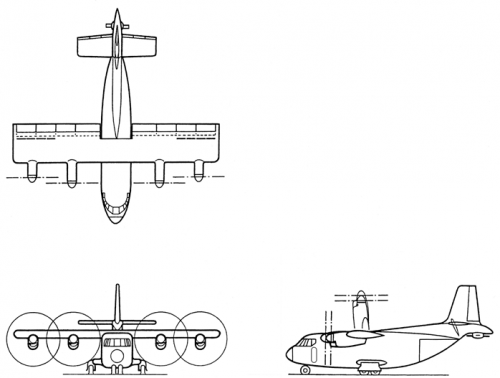
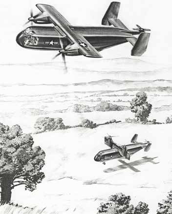
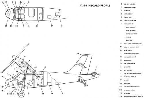
CL-72 VTOL Strike Reconnaissance Aircraft

NATO Basic Military Requirement No. 3 (NBMR-3), towards research and development of a V/STOL Supersonic Ground-Strike and Reconnaissance aircraft, was issued from the NATO Ad Hoc Mixed Working Group AC/169 (1960-1966). Canadair had started similar Preliminary Design (PD) proposals of possible short range configurations in mid-1958 to RCAF requirements, which included a basic VTOL ground attack mission, overload STOL mission, low level and high altitude reconnaissance, and the ferrying role. In a tactical role, the VTOL aspects of such a design proposal permitted operations independent from conventional airfields, or where airfields did not exist, and close to front lines, with immunity from enemy attacks by means of launch/recovery base dispersal. The lethal weapon payload designated to be carried was a selection between two 1,000 lb. bombs or a single 2,000 lb. tactical atomic bomb. The aircraft designs allowed for only a single pilot with another crewmember available with the associated launch and landing support equipment. The operational design aspects of such aircraft were examined, and the following configurations were proposed and assigned specific Canadair “PD” numbers.


Horizontal Riser Configurations (PD 7200 and PD 7201)

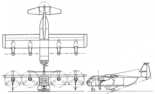
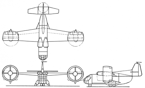
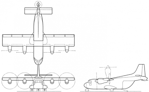
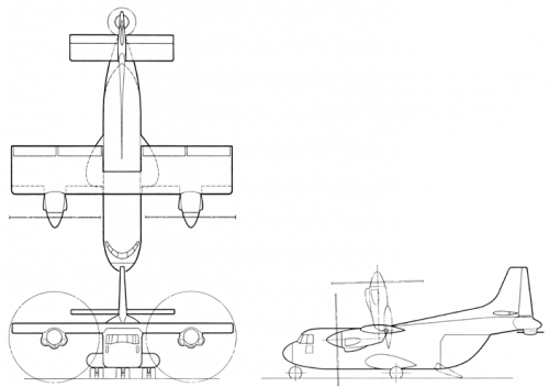
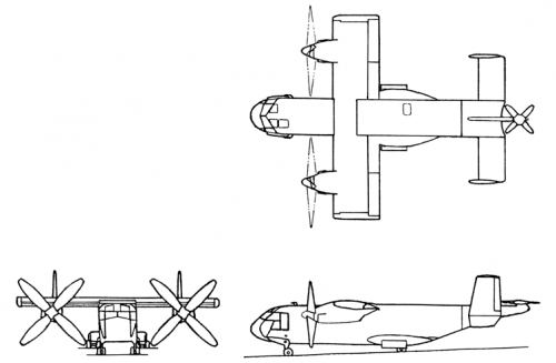
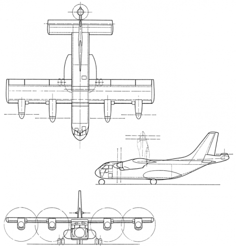
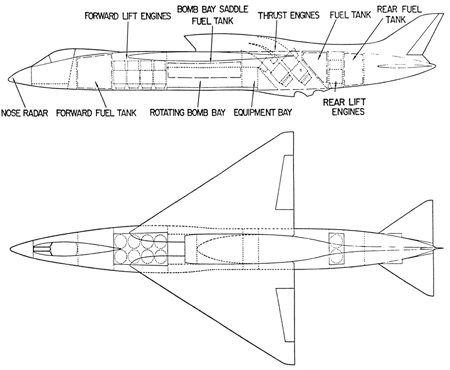
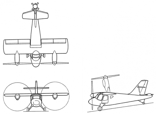
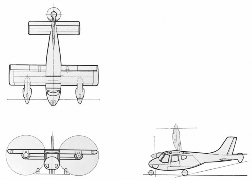
The basic jet lift CL-72 VTOL strike aircraft was to be 18.2 m (59.6 ft) long, with a wing span of 8.8 m (28.8 ft) providing a total wing area of 37.2 m² (400 ft²). The empty weight of the Horizontal Riser variants was envisioned at 9,251 kg (20,395 lb), with the gross weight peaking at 18,144 kg (40,000 lb). Two basic, but not standard, planform and engine layout designs were considered and some specifications were written. The PD 7200 configuration was seen with a typical rounded fuselage incorporating a conventional shoulder-mounted delta-wing. A delta-shaped horizontal tail arrangement was located on the aft fuselage under a centered characteristic vertical fin. The PD 7201 design was seen as a long narrow delta shape, almost a lifting body-type configuration, with flaperons at the flattened rear surface of the combined fuselage and wing incorporating vertical endplates and rudders positioned fully outboard.

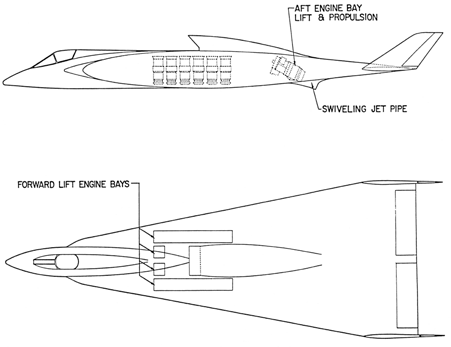
For the PD 7200 and PD 7201 configuration designs, the written specifications had called for four Orenda PS-16 thrust engines and ten Orenda lift engines, all rated at 16.4 kN (3,600 lbf) of thrust. The thrust engines were to provide general propulsion for conventional flight, or also providing double duty as a lift engine, these being fed by a single dorsal intake and exhausting via jet exhaust pipes located under the rear fuselage. The associated drawing for the PD 7200 configuration shows only two such thrust engines, arranged inline and apparently side-by-side, being fed by a single, horizontally bifurcated dorsal intake.

Of the specified ten Orenda PS-16 lift engines that were to provide the jet VTOL lift capability, eight of these are seen housed side-by-side in the forward fuselage area immediately aft of the cockpit, and two others similarly arranged at the rear of the aircraft, bracketing the bomb bay. The less detailed drawing of the PD 7201 configuration depicts a single combined thrust and lift engine with a swiveling jet exhaust pipe under the rear fuselage, although it may be speculated that there could be two such engines arranged side-by-side. There are apparently up to fourteen lift engines seen located at the mid-fuselage area. There does not appear to be any interior space available for the carriage of the bomb load and there is no mention of carrying exterior stores.

Assisted Take-Off Configurations (PD 7202 and PD 7203)

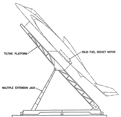
Various modes of achieving vertical launch and recovery were studied for the proposed CL-72 assisted take-off aircraft configurations. These design concepts offered highly mobile systems to be sustained without the need for large ground support facilities. They were to be capable of increased operational flexibility particularly in rough area conditions. One radical and tested approach to the capability of getting military aircraft safely airborne away from enemy targeted areas (namely civilian and military airfields) was developed in the mid-1950s as the mobile Zero-Length Launch (ZELL) technique. Deployed openly or within hardened shelters near likely targets, the aircraft with its load of conventional or nuclear weapons would be virtually catapulted into the air at a moments notice by a solid-fuel rocket thus obviating the need for conventional runways or unprepared strips near the front lines. This launch method was used initially with early large cruise missiles and reconnaissance drone systems, then tested extensively with such familiar manned aircraft as the Republic F-84 Thunderjet, North American F-100 Super Sabre, and the Lockheed F-104 Starfighter. For the proposed ZELL method of getting airborne, the conventional and narrow delta CL-72 strike aircraft, mounted atop a tiltable platform, would have solid-fuel rocket motors attached to a reinforced lower fuselage hardpoint for launch. Following a short burn time to get the aircraft into the air and quickly up to flying speed, the rocket boosters would be jettisoned, the aircraft would complete its mission under its own power, then recover like a conventional, or as a VTOL aircraft at a safe location.

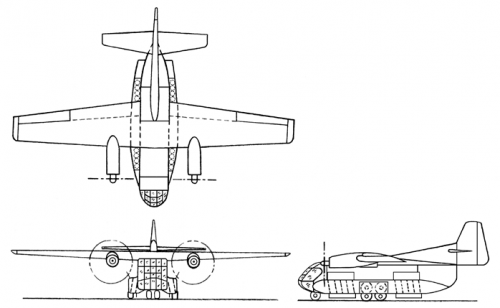
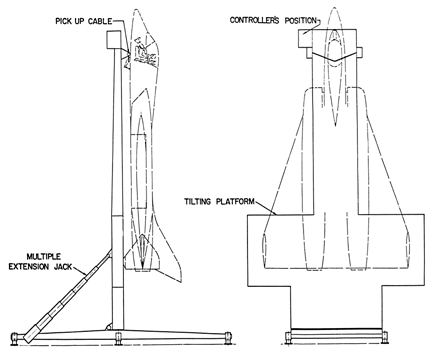
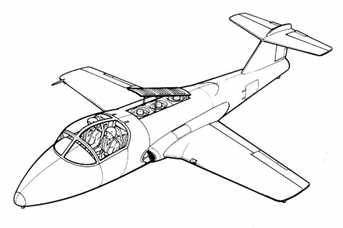
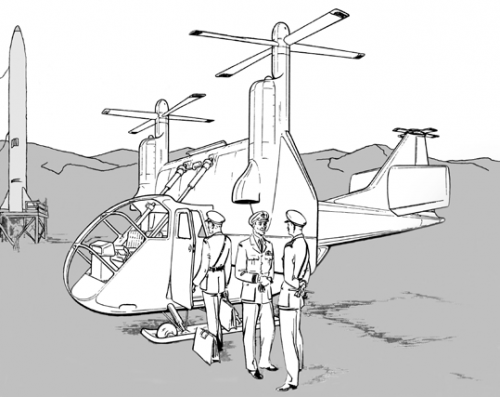
Another method to get the aircraft into the air had a modified CL-72 aircraft suspended, via a nose hook, onto a “clothesline” pickup cable mechanism, on a readily transportable, inverted “T”-shaped, tiltable launch and recovery platform. The platform and attached aircraft would be raised from the horizontal to the vertical position by means of large hydraulic actuators for the launch and recovery operations. As a single seat, multi-jet tail-sitter, this particular design was to be a variant of the long Narrow Delta Wing configuration, with a central vertical stabilizer, squared fuselage side air intakes, and dual jet exhausts at the rear. At the wing tips were small vertical endplates extending above and below, and a single vertical fin was centered aft.

The lower portion of each had a skid plate installed as a buffer against the tiltable platform. The aircraft would be launched vertically, then transition to horizontal flight in order to perform its mission, and finally be retrieved back to the platform in a vertical orientation. This interesting method of operation was similar to that perfected during the Ryan Aeronautical Company X-13 Vertijet flight-test programme of 1955-1958. With this particular CL-72 variant, a dedicated “Land-on Controller” was to be stationed atop the platform to perform launch and retrieval operations in order to alleviate the aircraft pilot from these demanding tasks, especially following a trying mission.

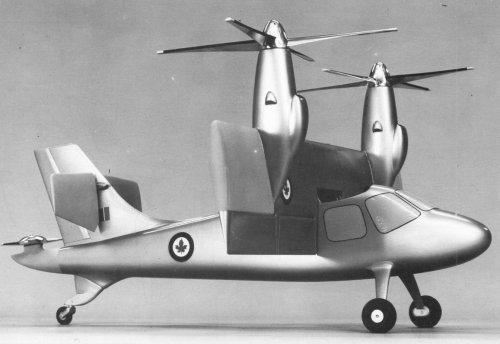
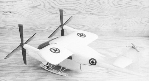
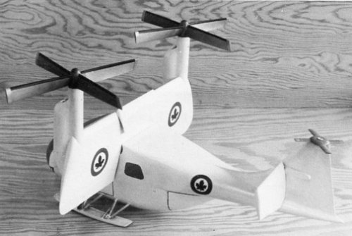
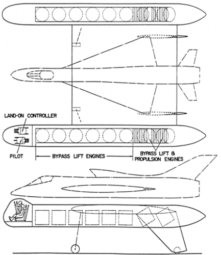
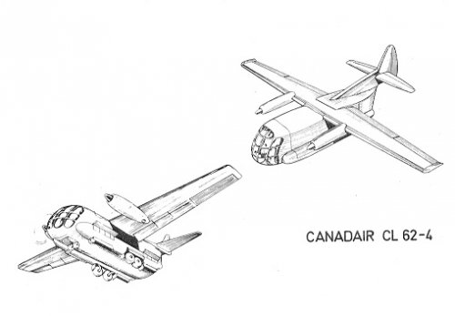
Composite Aircraft Configuration (PD 7204)

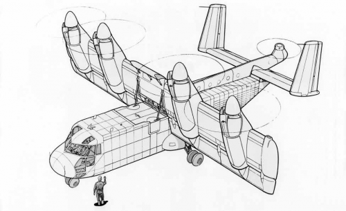
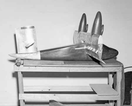
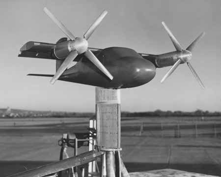
Truly the most unique and complex of the CL-72 vertical launch and recovery configurations, was the ingenious VTOL composite aircraft idea. The mission aircraft was to be mounted centrally upon a flat-surfaced, mobile lifting platform that was in itself powered by multiple bypass lift and propulsion engines. This was an idea similar to the English Electric P.17A aircraft spelled out in General Operational Requirement (GOR) 339 (the precursor to the TSR.2) proposal, put forth in collaboration with Short Brothers, who had developed the idea for a P.17D VTO jet-lift platform in 1957. In this proposed design scheme, sixteen Orenda lift and propulsion engines of the Canadair lifting platform were to be vertically mounted in tip pods interconnected by the flat launch and recovery platform, with all engine intake openings located at the top of the pods. The platform’s pilot and a rearward facing “land-on controller” were seen housed in a bulbous cockpit at the forward end of the left pod. The composite aircraft combination sat high atop two fixed and stalky forward undercarriage struts and two rear sets of wheeled gear attached to swept, downward-angled fins. To conserve the mission aircraft’s fuel, the platform would have to be positioned close to the target area prior to launching the aircraft. Following completion of the operation, the mission aircraft was to be recovered back aboard the low flying VTO platform, or alternatively to an available airstrip if necessary. The successful landing and recovery of the mission aircraft back to the platform following a stressful mission would have been somewhat problematic at best.

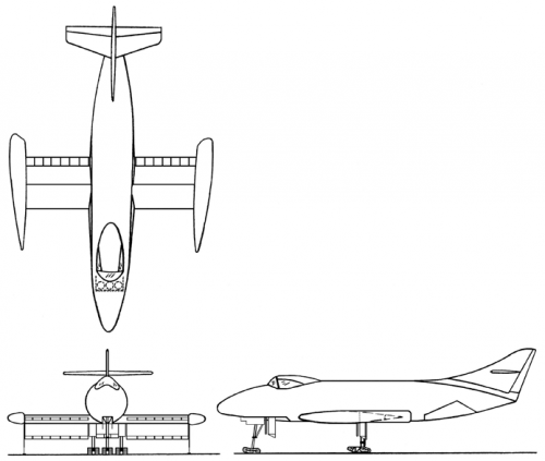
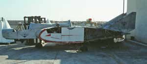
Not a Canadair product, but remarkably similar to the PD 7201 planform layout was the LeBel experimental VSTOL of December 1962. A singular example, in poor condition, seen by the author in 1993 at the Chino Airport, California, bore the long narrow delta shape of the ‘7201. Its single turbojet engine powered dual sets of wooden propellers mounted on a rotating arm on the center fuselage. The operating propellers would lie flush with the upper fuselage providing VTOL capability via controlled louvers at the bottom of the fuselage. For forward flight, the propellers would be pivoted up and forward to a vertical position. Dual vertical tails were located just inboard of the wingtips. Canada Patent No.654,548 appeared on the nose.
 

Attachments

  • Lebel Experimental VSTOL.jpg
    Lebel Experimental VSTOL.jpg
    8.1 KB · Views: 63
  • PD 7204.png
    PD 7204.png
    101.9 KB · Views: 52
  • PD 7202 & 7203 b.png
    PD 7202 & 7203 b.png
    48.8 KB · Views: 49
  • PD 7202 & 7203 a.png
    PD 7202 & 7203 a.png
    48.1 KB · Views: 44
  • Narrow Delta Wing (PD 7201).png
    Narrow Delta Wing (PD 7201).png
    42.7 KB · Views: 47
  • Conventional Delta Wing (PD 7200).png
    Conventional Delta Wing (PD 7200).png
    64.9 KB · Views: 53
CL-41J VTOL Jet Trainer

In June 1961, preliminary studies were made by Canadair that were initially tailored to the NATO V/STOL Supersonic Ground-Strike and Reconnaissance aircraft concept, to determine the merits of a highly modified Canadair CL-41 aircraft design as a companion type VTOL jet trainer. The side-by-side seating configuration would provide an ideal and efficient instructional environment, as had been evident with the successful tests and demonstrations of the first prototype CL-41 aircraft.

With a standard Canadian Orenda-built J85-CAN-40 engine providing the forward propulsion, an additional three Rolls Royce RB162 direct-lift jet engines, mounted inline vertically behind the cockpit in a lengthened center fuselage, would have provided the VTOL capability for the proposed CL-41J. A louvered, forward opening air inlet door would be raised to a canted position for the direct-lift engines’ operation during VTOL flight, then it would be retracted flush to the fuselage for the cruise portion of flight. A variable exhaust system on the underside of the aircraft would have controlled the vertical thrust vector.

With four thirsty jet engines to feed, additional fuel would have been required and that would have possibly been made available by the addition of bladder tanks in the inboard sections of the wings and in the wing-to-fuselage side fairings. Jettisonable fuel tanks fitted to pylons under the wings would probably have been necessary for any type of a satisfactory training mission to be accomplished. It is not known how roll and yaw were to be controlled when the aircraft was to be operated in the VTOL regime. Pitch may have been controlled possibly by modulating the thrust of the forward and/or rear lift jet engines.
 

Attachments

  • CL-41J.png
    CL-41J.png
    99.8 KB · Views: 51
CL-73

The CL-73 was conceived in August 1958 as a small twin engine tilt-wing V/STOL reconnaissance / Army liaison / light observation aircraft per US Army Study Requirements ASRI-60 sponsored jointly by Canadair and the Canadian DRB. Comparative studies suggested that the proposed CL-73 could provide the same or better capabilities as the combined Cessna L-19 light fixed-wing aircraft and the Bell H-13 helicopter, which were then in military service.

This concept was designed primarily as a flying test bed to provide full-scale data on transition characteristics, stability and control of a hybrid tilt-wing/deflected slipstream V/STOL aircraft. This vehicle would also investigate piloting techniques and operational procedures for the larger V/STOL transport aircraft designs that Canadair was developing for the future.

Besides the basic design, no less than ten additional CL-73 model Army reconnaissance conceptions were proposed, some with alternate engines and installation configurations, some of these employing a selection of propeller diameters.

A 1/5th-scale wind tunnel model, built in 1959, designed slightly different from the 3-view version presented above, was one of the first VTOL models tested on the Canadair VTOL Mobile Test Rig. Main tests performed included the placement of the horizontal stabilizer in such configurations as the rear fuselage, mid and high placement on a squared vertical tail to verify aerodynamic characteristics at various wing-tilt angles.

CL-73 Specifications:
The basic CL-73 aircraft was to have an overall length of 8.4 m (27.5 ft) and a maximum height of 4.5 m (14.7 ft) with the wing in VTOL mode. It was to sit on two low-pressure tires mounted on fixed cantilever leaf-spring struts and a tail-skid gear. The rectangular planform wing with full-span slotted flaps had a span of 8.1 m (26.5 ft) with an area of 14.8 m² (159.0 ft²). Power was to be provided principally by two 250 shaft-horsepower Allison T63-A-3, or alternatively, two General Electric T58 engines driving two 4-bladed 3.6 m (12.0 ft) diameter LH and RH propellers and the 4-bladed 1.2 m (3.8 ft) diameter tail rotor.

Alternatively, as the CL-73A variant, power was to be supplied by two Allison Model 252-C2 engines, each of which consisted of twin T63-A-3 engines with a common integral gearbox.

The CL-73 would nominally carry a crew of two in a side-by-side seating arrangement with a maximum of two passengers, or alternatively, with the rear seats removed, could provide up to 1.5 m³ (53.5 ft³) of cargo space. Gross takeoff weight of the basic aircraft in VTOL mode was set at 1,628 kg (3,590 lb), in STOL mode at 1,962 kg (4,325 lb) and for the Ferrying role 2,223 kg (4,900 lb).

As the CL-73A, the VTOL and STOL weights were upped accordingly to 2,195 kg (4,840 lb) and 2,499 kg (5,510 lb) respectively. At 200 knots (370 km/h / 230 mph), the cruise range in VTOL mode was 570 km (308 nm), STOL was 566 km (306 nm) and the Ferrying range was set at 2,960 km (1,600 nm).


Photo captions:
1. This first windtunnel model of the CL-73 displays a mid-point installation of the horizontal stabilizer. In this slipstream deflection mode, note the numerous flap deflector actuators atop the wing.
2. The complete CL-73 model is mounted on the Mobile Test Rig during tests of the lower placement configuration of the all-moving horizontal stabilizer, in November 1959.
 

Attachments

  • CL-73.png
    CL-73.png
    83.5 KB · Views: 54
  • CL-73 model 1.jpg
    CL-73 model 1.jpg
    19.4 KB · Views: 46
  • CL-73 model 2.jpg
    CL-73 model 2.jpg
    19.4 KB · Views: 46
CL-74

The CL-74 was yet another conception from August 1958 for a small, twin engined, tilt-wing/deflected slipstream V/STOL Army liaison aircraft. Two versions were proposed, a typical 5 to 7 place variant for production and from December 1958, the CL-74A, a smaller 2 to 4 place aircraft intended to be a flying test bed with potential development, both being funded by Canadair and the DRB.

CL-74 Specifications:
The somewhat compact, yet bulbous fuselage likened to that of a helicopter, had a generous amount of cockpit window area for added crew visibility in all directions. This large quantity of glazing would have undoubtedly produced a greenhouse effect making it somewhat uncomfortable for the crew and passengers. Double clamshell cargo doors were at the rear under the high placed tail boom arrangement.

Mounted midway up the vertical tail, the all-moving horizontal-stab rotation was coordinated with the selected wing tilt. A combination wheel and skid main undercarriage was provided to facilitate off-runway operations. The gear was retractable, being pulled up to fit up against the underside of the fuselage.

The proposed CL-74 was to have a projected length of 8.1 m (26.7 ft), height of 4.4 m (14.3 ft), and a wingspan of 7.1 m (23.3 ft) with an area of 12.0 m² (130.0 ft²). The wing incorporated full-span slotted flaps for slipstream deflection to improve the STOL capability and provide effective control during transition.

The basic version was to be powered by two 1,250 shaft-horsepower General Electric T58-8 free turbine engines driving 4-bladed, 3.0 m (10.0 ft) diameter, LH and RH controllable pitch propeller sets. For longitudinal control, a 2-bladed, 1.4 m (4.5 ft) diameter tail rotor assembly was mounted atop the vertical tail. With a 555 km (300 nm) maximum range, gross takeoff weight of the basic aircraft in VTOL mode was set at 3,472 kg (7,655 lb), in STOL mode at 4,019 kg (8,860 lb), and in a STOVL mode was 3,684 kg (8,122 lb).


Captions:
1-2. A small desktop display model of the CL-74 from January 1959, posed in the proposed modes of operation, sports RCAF roundels and the serial number 19101, the number officially assigned to the first Canadair-built CL-13 Sabre Mk 1 in 1950.
3. Three representative cabin layout and loading arrangements of the CL-74 liaison airplane are illustrated in these proposed interior cutaway diagrams.
4. This artist’s conceptual drawing shows a scenario of a CL-74A, in VTOL configuration, having delivered some military personnel to a remote rocket launching complex. The compact size of the airplane is readily apparent, highlighting the need to raise the wing to the vertical for personnel ingress and egress. The placement of the dual wing tilt hydraulic jacks, straddling each side of the cockpit interior, is also noteworthy.
 

Attachments

  • CL-74 drawing.png
    CL-74 drawing.png
    130.8 KB · Views: 94
  • CL-74 cabin layouts.png
    CL-74 cabin layouts.png
    405.6 KB · Views: 90
  • CL-74 model 2.jpg
    CL-74 model 2.jpg
    13.7 KB · Views: 80
  • CL-74 model 1.jpg
    CL-74 model 1.jpg
    14.6 KB · Views: 81
CL-84 Light V/STOL Original Concepts

After a detailed consideration of all factors involved, it was finally concluded, by early 1959, that the hybrid tilt-wing/deflected slipstream configuration offered the most promise for a simple and practical airplane. It was deemed that such a configuration could be designed and built without major development problems and would be as efficient as more complicated types.

A small, two-engine tail-sitter design was conceived of as an inexpensive research vehicle, so a powered 1/7th-scale model was built and tested during low-speed wind tunnel trials at the Convair Low Speed Wind Tunnel, from June through November 1960.

The earliest CL-84 was designed under US Army Study Requirements ASRI-60 as a twin engine tilt-wing V/STOL aircraft for the army reconnaissance / liaison and light observation roles, jointly sponsored by Canadair and the DRB. Other applications included emergency transport, artillery fire control, ground support, and casualty evacuation. As was the case for the former CL-73 design, this CL-84 version was proposed to replace the light observation aircraft combination of Cessna L-19 and Bell H-13 helicopter in their diverse military roles.

This aircraft was intended to serve two primary purposes. As a flying test vehicle the airplane would provide full-scale data on the transition characteristics, stability and control of the tilt-wing/deflected slipstream configuration, and would permit detailed investigation of piloting techniques and operating procedures of such VTOL vehicles.

Secondly, as a military vehicle, the CL-84 was designed to perform a reconnaissance mission with a crew of two and up to 227 kg (500 lb) of equipment, or in the observation and liaison roles, could carry the crew, three passengers and 45 kg (100 lb) of baggage. Additional passengers or increased payload could be carried under STOL or normal airplane flight conditions.

This first CL-84 incarnation, larger yet basically similar in configuration and detail design to the CL-73, was to have a length of 10.1m (33.3 ft) and a height of 3.3 m (10.9 ft) while sitting upon elongated cantilever leaf spring, fixed landing gear. The low aspect ratio wing with a span of 9.5 m (31.0 ft), encompassing an area of 20.2 m² (217 ft²), was of a rectangular planform with full-span slotted flaps. Mounted midway up the vertical tail, the all-moving horizontal-tail rotation was coordinated with the selected wing tilt.

The aircraft was to be powered by two 500 shaft-horsepower Pratt & Whitney Canada (P&WC) PT6B-2 engines to drive two, 4-bladed, 4.3 m (14.0 ft) diameter handed interconnected propellers, and the 4-bladed, 1.3 m (4.3 ft) diameter tail rotor for pitch control in the transition and hover.

An alternative power plant arrangement was to include two Allison Model 252-C2 engines, each of which consisted of twin T63-A-3 free turbine engines with a common integral gearbox. Available takeoff power would be slightly increased using this engine configuration, however, this would be balanced by a small increase in fuel consumption during the cruise specific portion of the flight such that the overall performance is virtually unaltered.

Maximum speed at the military power setting was to be from 220 to 222 knots (407 to 411 km/h / 253 to 255 mph). The cruise range in VTOL mode was to be 483 km (261 nm) with slightly less, at 477 km (258 nm), for the STOL mode. For Ferrying flight, a range of up to 2,960 km (1,600 nm) was perceived.

The gross takeoff weight in the VTOL mode was to be 2,676 kg (5,900 lb), in STOL it was set at 3,182 kg (7,014 lb) and for Ferrying was 3,502 kg (7,720 lb).

In this initial CL-84 design phase the complex flight control system was becoming more finalized towards that to be used on a production V/STOL type of aircraft. One of the main factors required by Canadair designers was to have the movements of the control column and rudder pedals produce normal aircraft response under all flight conditions. Separate collective-pitch, with additional lever and yoke controls for the transition and hover portions of flight were deemed too complex, and would possibly over tax the flight crew, such systems having borne out these instances with some other manufacturer’s V/STOL aircraft designs. Mechanical reliability with minimum complication was the key to the successful design of this control system.

For a STOL or VTOL take-off and hover, the wing was to be mechanically tilted to an upright position by means of hydraulically driven ball-screw jack assemblies. Altering the main propeller pitch while the engine rpm remained constant would control the vertical motion of the aircraft. Roll would be controlled by the differential variation of the main propeller pitch, and yaw would be controlled by a series of spoilers located forward of the wing flaps within the propeller slipstream. Longitudinal pitch control in the transition and hover would be maintained by varying the blade angle on the upward facing tail rotor assembly.

During the transition and forward flight regimes, the wing would be tilted to the horizontal position by the screw jacks. Roll control would then be transferred via simple mechanisms to the spoilers, yaw control would revert typically to the rudder, and pitch control to the horizontal tail as the tail rotor is stopped.

Movement of the horizontal stab and wing flap deflections would all be coordinated with the wing tilt so as to minimize the pitching moments and increase lift. The main propeller pitch control would be transferred to a constant speed drive unit and the aircraft’s forward speed would be determined by the engine power setting. The propellers were designed to rotate in opposite directions to derive the maximum benefit from the entire wing being bathed in the slipstream. Bevel gears and shafting interconnect the main propellers so that both would continue to operate if one engine fails, the faulty engine becoming isolated by an overrunning clutch system. With this design concept showing great promise for further development into an actual flying test article, additional analysis of VTOL propeller design, and intensive wind tunnel in conjunction with Mobile Test Rig trials were continued over the next few years. Little focused activity took place on this design until the completion of the US Tri-Service V/STOL Transport competition in 1961. A great deal of knowledge was generated during the NATO design work phase and this was subsequently used to update and improve this small CL-84 design. Finally, on 31 January 1963, the Canadian Government announced that it had agreed to enter into an arrangement with Canadair Limited to support the operational development of the CL-84 light VTOL tilt-wing aircraft.

Initially two prototype aircraft, powered by two, 600 horsepower P&WC PT6 turbine engines, were ordered built for testing and development towards potential future sales. Refinements to the design would permit the accommodation of up to ten, including the crew. It was also to be capable of carrying a maximum of 4 litters, or a modest cargo load with the cabin seats removed. This order was further defined as building a principal prototype demonstrator aircraft, with the construction of a second complete set of components to be used either as a spares source to support the test aircraft, or to be built up as a second aircraft if justified.

The estimated cost of the new programme was $10 million CDN, with the Department of Defence Production covering 75 per cent and Canadair picking up the remaining 25 per cent. Projected development had prototype aircraft being built and flight tested within two years, with a follow-on demonstration programme aimed at potential customers shortly thereafter. Not only were military customers to be courted, civilian commercial markets were foreseen for such an aircraft in the realm of surveying the vast tracks of northern territories, as well as being marketed as a short-haul transport between remote regions and even urban city centers.

Design studies of a larger developmental version of the CL-84 for the military, powered by either Lycoming T53 or General Electric T58 engines, both rated in the 1000 shaft-horsepower range, were also being seriously considered at this time. A want for more cargo and troop carrying capability with an associated larger, rear located cargo door, and necessarily more powerful engines, drove the push for a new revised design.


[This ends the section of the book devoted to pre-Dynavert designs and projects]


Captions:
3-4-5. This first model design of the Canadair CL-84 configuration was basically a growth version of the former CL-73 V/STOL tiltwing airplane. Note the robust tail wheel gear design and the mid-tail placement of the horizontal stabilizer in these photos realistically demonstrating the exquisitely handcrafted model’s articulating capabilities.
6. By 1962, an improved light CL-84 design incorporates a new tricycle landing gear arrangement with a large tail bumper, possibly to permit tilt-back takeoff capability (similar to the early CL-62-1 model). The wide-chord horizontal stabilizer has now been relocated to the rear fuselage. Note how the propeller diameter appears too large for standard ground running when the wing is in the fully horizontal position.
7. This general arrangement of the revised light CL-84 tilt-wing design details the interior layout and control systems components. As well, a smaller rotating horizontal stabilizer assembly has been relocated from the original mid-tail placement to a lower position on the aft fuselage.
 

Attachments

  • CL-84 improved, cutaway.png
    CL-84 improved, cutaway.png
    346.9 KB · Views: 68
  • CL-84 improved.png
    CL-84 improved.png
    133.3 KB · Views: 64
  • CL-84 original, model 3.jpg
    CL-84 original, model 3.jpg
    11 KB · Views: 213
  • CL-84 original, model 2.jpg
    CL-84 original, model 2.jpg
    14.4 KB · Views: 220
  • CL-84 original, model 1.jpg
    CL-84 original, model 1.jpg
    25.3 KB · Views: 225
  • CL-84 original, inboard profile.png
    CL-84 original, inboard profile.png
    179.5 KB · Views: 232
  • CL-84 original.png
    CL-84 original.png
    76.6 KB · Views: 263
This ends the pre-Dynavert Canadair VTOL projects.

REMINDER: this topic is made up of excerpts from that document, previously shared by forum member Kagemusha in the CL-84 topic, and entitled:
DESIGN AND DEVELOPMENT HISTORY OF THE CANADAIR CL-84 V/STOL TILT-WING AIRCRAFT (written by Bill Upton, Canada Aviation Museum Research Volunteer, and published by the Canada Aviation Museum).

http://documents.techno-science.ca/documents/CASM-Aircrafthistories-CanadairCL-84VSTOLhistory.pdf

index.php


The Canadair CL-84-1 Dynavert and subsequent Canadair/General Dynamics proposed derivatives are covered in a separate topic:
https://www.secretprojects.co.uk/forum/index.php/topic,4267.0
 
Illustrations used in a Dokumentation für die Entwicklung eines V/STOL-Transporters (Arbeitsunterlagen für Vorbereitungsphase / Zusammenstellung von Projektideen), published bei VFW Bremen.
 

Attachments

  • CL-62-2.jpg
    CL-62-2.jpg
    36.6 KB · Views: 62
  • CL-62-3.jpg
    CL-62-3.jpg
    49 KB · Views: 65
  • CL-62-4.jpg
    CL-62-4.jpg
    33.7 KB · Views: 71
Wow,amazing drawings my dear Boxkite,many thanks.
 

Similar threads

Back
Top Bottom