Bristol Siddeley "Flying Pig" V/STOL 1960

overscan (PaulMM)

Administrator
Staff member
Joined
27 December 2005
Messages
16,317
Reaction score
18,572
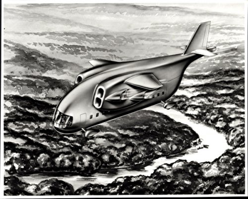
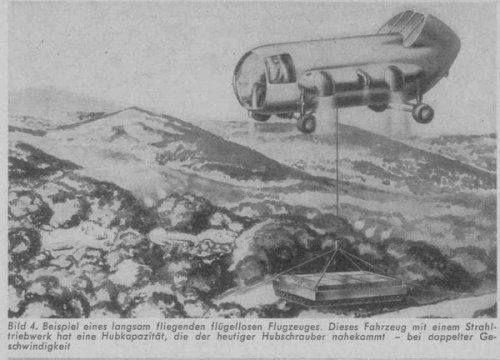
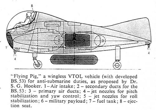
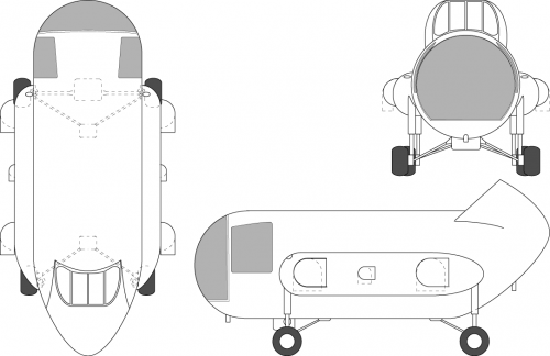
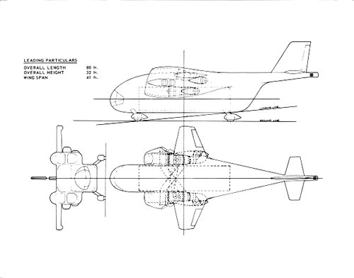
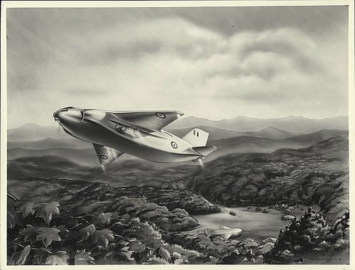
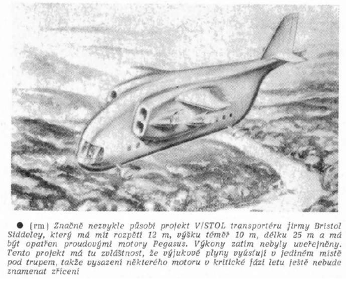
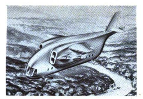
Found some brief specs on this one in an Air Pictorial.

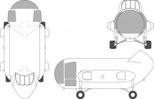
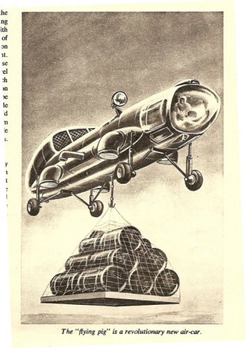
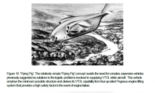
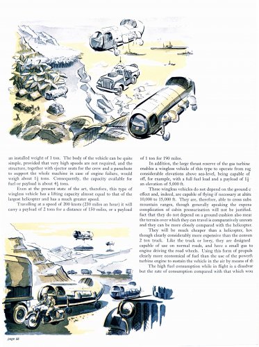
  • VTOL transport, partly replacing cancelled H.S.681, designed for minimum structure weight, sized around payload with smallest wings possible to support weight during cruise. In low speed flight relies on partial deflected thrust.
  • Designed by a team under Sir Stanley Hooker.
  • Powered by 4 uprated Pegasus engines, rated at 24,000lb each.
  • MTOW: 70,000lb
  • Payload: 20,000lb
  • Cruise speed: 330mph
  • Dimensions: 80ft length, 41ft span, 32ft height.
 

Attachments

  • 1960 Flying Pig.jpg
    1960 Flying Pig.jpg
    76.7 KB · Views: 1,737
  • 1960 Flying Pig 2.jpg
    1960 Flying Pig 2.jpg
    286.9 KB · Views: 1,534
But it still had wings. Totally unnecessary, as can be seen by
this concept, described as "slow flying, wingless aircraft" in
FlugWelt-60-I !
 

Attachments

  • Bristol_wingless_VTOL.JPG
    Bristol_wingless_VTOL.JPG
    45.3 KB · Views: 1,360
here's the version i found...

http://www.secretprojects.co.uk/forum/index.php/topic,2504.msg33446.html#msg33446

cheers,
Robin.
 
Crosslink to topic dealing with a 1959 NASA Technical Note on wind tunnel studies on a model of a Wingless jet VSTOL Transport: http://www.secretprojects.co.uk/forum/index.php/topic,7142.0.html
 
I've knocked up a GA of the Bristol 'Flying Pig'.

Any idea what its real designation was?

Chris
 

Attachments

  • Flying_pig_early_A4.png
    Flying_pig_early_A4.png
    70.6 KB · Views: 794
CJGibson said:
I've knocked up a GA of the Bristol 'Flying Pig'.

Any idea what its real designation was?

Chris

Maybe it's a proposal by Bristol ENGINES, not by the aircraft manufacturer Bristol?
 
How was it going to get lift in forward flight?
 
1) The first design shown. Can you imagine how loud it would be
2) The wingless designs. Flight time in minutes due to the incredibly high fuel consumption
 
CNH said:
How was it going to get lift in forward flight?

Jet lift only ! The Harrier can, or better, has to do the same at very low forward speed.

Kevin Renner said:
1) The first design shown. Can you imagine how loud it would be
2) The wingless designs. Flight time in minutes due to the incredibly high fuel consumption

1) Dependening on the task, that may mot matter !
2) Judging the sketch, it was intended as a kind of roadable flying crane. Refulleing during attaching the
sling load may have been a suitable scenario, I think.
 
My reading of the sketch is:

Vectored thrust with rotating nozzles.
Pegasus installed backwards with intake at rear
Directional control by puffers shown at nose, tail and sides (the side ones might/might not rotate) I might 'fix' the side ones.
Driven front wheels as there appears to be a drive shaft and a transmission under the froward fuselage.
Flying crane for moving underslung loads short distances (20km?), but could be driven/manoeuvred on the ground.
Wheels/tyres look a bit beefy for mere landing gear.

I've found another sketch showing it in 3/4 view from below so have amended the drawing. This sketch shows bulged windows for better downward view and the shaft drives for the wheels.

Also used the payload shown to estimate the lifting capacity - 12 x 45 UK Gal drums (54 US Gal) - assume 6.08lb/US Gal for gasoline = 12 x 54 x 6.08 = 3940lb (1787kg)

Add in the odds and sods for slinging etc - looks like 4000lb at least.

Chris
 

Attachments

  • Flying_pig_early_A4.png
    Flying_pig_early_A4.png
    71.6 KB · Views: 1,119
  • BS Flying Pig.jpg
    BS Flying Pig.jpg
    111.3 KB · Views: 193
Sorry for not having reacted correctly at once, although I have the source about the
Pegasus engine at hand, "Pegasus, The Heart Of The Harrier" by Andrew Dow:
About the "Flying Pig", he says, that it was conceived by Stanley Hooker as a means
of providing vertical lift for battlefield materials. The vehicle was designed with front and
back halves, allowing easy installation of the Pegasus engine, which was mounted back-
wards. Hot and cold nozzles were controllable independently to allow for propulsion by
the cold nozzles at the rear providing some forward thrust. Flight controll was achieved
by four puffer jets, the pilot was provided with a Martin-Baker ejection seat and the
road wheels were driven by a 100 shp turbine located below and behind the pilot.
Length was to be 22 ft and, with the puffer jets extended, 11 ft 4 in wide.
The twin engined version, with the engines side-by-side was designed by David Maxwell.
 
CJGibson said:
My reading of the sketch is:

Vectored thrust with rotating nozzles.
Pegasus installed backwards with intake at rear
Directional control by puffers shown at nose, tail and sides (the side ones might/might not rotate) I might 'fix' the side ones.
Driven front wheels as there appears to be a drive shaft and a transmission under the froward fuselage.
Flying crane for moving underslung loads short distances (20km?), but could be driven/manoeuvred on the ground.
Wheels/tyres look a bit beefy for mere landing gear.

I've found another sketch showing it in 3/4 view from below so have amended the drawing. This sketch shows bulged windows for better downward view and the shaft drives for the wheels.

Also used the payload shown to estimate the lifting capacity - 12 x 45 UK Gal drums (54 US Gal) - assume 6.08lb/US Gal for gasoline = 12 x 54 x 6.08 = 3940lb (1787kg)

Add in the odds and sods for slinging etc - looks like 4000lb at least.

Chris

Incidentally, I suspect that the searchlight shown in the 3/4 view is an IR one. Would make sense for a battlefield supply vehicle.
 
Hi,


the Bristol Flying Big; Early VTOL Aircraft
(before 1967)
Published by Dennis Hawkes at Smashwords
 

Attachments

  • Bristol.png
    Bristol.png
    193.4 KB · Views: 851
Great find, thanks for sharing BB.


A cautionary tale showing why engine designers should not stray into aircraft design perhaps - just imagine the beating the slung payload would get from the exhaust, with the cable whipping around as the load is buffeted about etc.
 
Any idea why the cruise speed was limited to 330 mph? A VTOL platform should have a power to weight ratio that would allow it to go faster (other considerations aside).
 
Possibly reaching the limits of control authority of the puffer ports? With a conventional design you get more airflow over the control surfaces the faster you go, with this design your ability to counteract pitch or yaw forces is pretty much constant and doesn't scale with speed.
 
From Air Pictorial 1967.
 

Attachments

  • 1-1.png
    1-1.png
    352.8 KB · Views: 34
  • 2-1.png
    2-1.png
    122.2 KB · Views: 33
  • 3-1.png
    3-1.png
    250.7 KB · Views: 43
Back
Top Bottom