Boeing MRF-24X

targetpractice

ACCESS: Confidential
Joined
30 December 2024
Messages
165
Reaction score
616
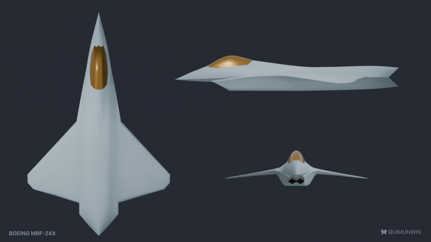
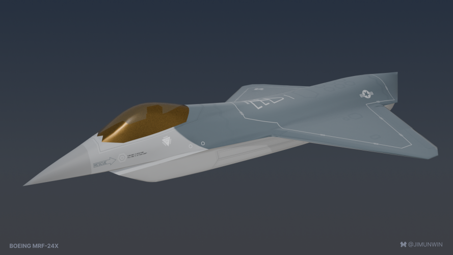
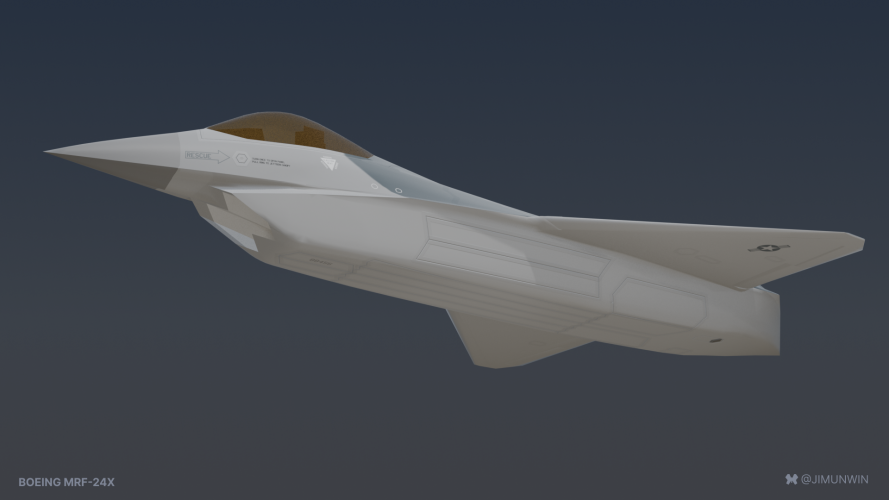
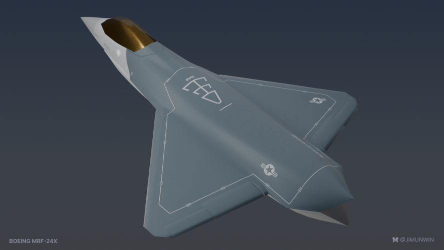
Hello! I'm not sure what the usual rules are for this stuff, but I wanted somewhere to share my progress and get feedback on a model I'm making. Mods feel free to move / rename / delete as appropriate.

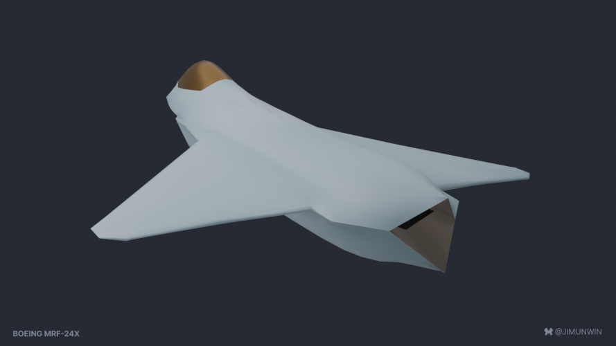
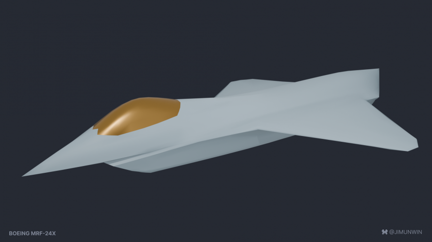
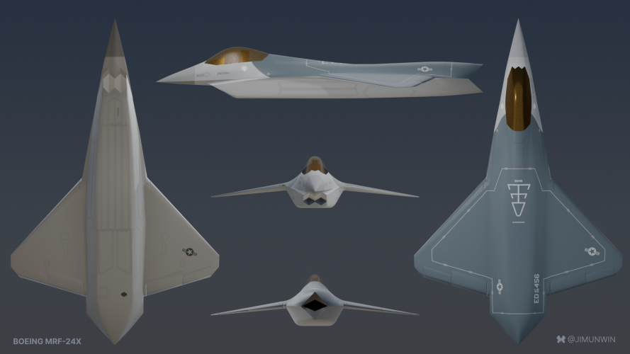
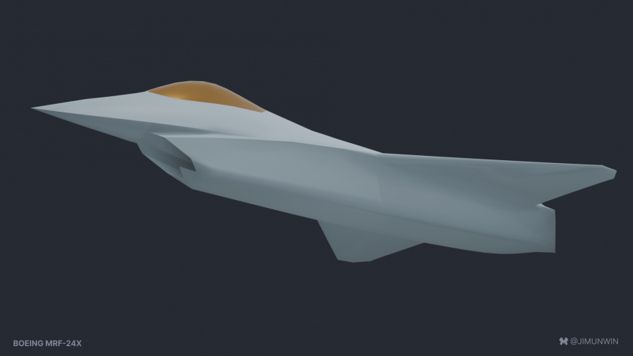
I chose the MRF-24X mainly because I wanted to model that intake! I love how weird it looks from straight on, but how cool it looks from almost any other angle.

Next steps are to model separate wing elements, weapon and gear doors. However, I'm learning 3D/Blender as I go along (my day job is more likely to find me in a spreadsheet), and I won't pretend to be as quick or as skillful as many others on the forum. The main liberty I have taken so far is in modeling the way the front chine is shaped. I don't think the existing 3 view is conclusive, I really like the other (later?) versions of the plane, and other tangential sources (wind tunnel models etc) also seem to feature the double chine.

Thoughts and feedback are always appreciated!
 

Attachments

  • MRF-24X bottom.png
    MRF-24X bottom.png
    381.8 KB · Views: 284
  • MRF-24X orthos.png
    MRF-24X orthos.png
    405 KB · Views: 213
  • MRF-24X rear.png
    MRF-24X rear.png
    392.4 KB · Views: 187
  • MRF-24X top.png
    MRF-24X top.png
    404.9 KB · Views: 189
Still quietly wrestling with this.

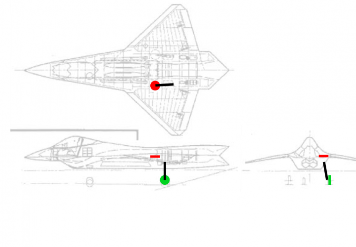
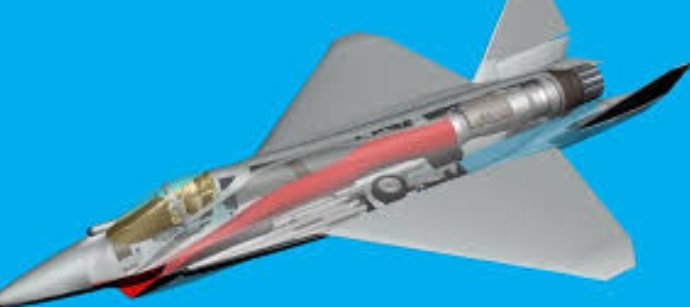
I have come to bit of an impasse though, in that I can't figure out how the undercarriage is supposed to work! I've attached a rough diagram of my best guess so far (with red and green representing up and down respectively), but that still means the gear has to swing through ~130 degrees which seems... unlikely.

Any advice or real world examples would be much appreciated!

(Of course the original drawings might be wrong or misleading) mrf-24x_undercarriage.png
 
Still quietly wrestling with this.

I have come to bit of an impasse though, in that I can't figure out how the undercarriage is supposed to work! I've attached a rough diagram of my best guess so far (with red and green representing up and down respectively), but that still means the gear has to swing through ~130 degrees which seems... unlikely.

Any advice or real world examples would be much appreciated!

(Of course the original drawings might be wrong or misleading)View attachment 779123
For inspiration...
View: https://youtu.be/zvuzkEfky-g?si=Gt9tOVvDX-jt8haM
 
That gear layout looks pretty simple. Probably a simple pivot for the main leg and a separate wheel rotation unit during the sweep up/down. F-104 is another real world example.
 
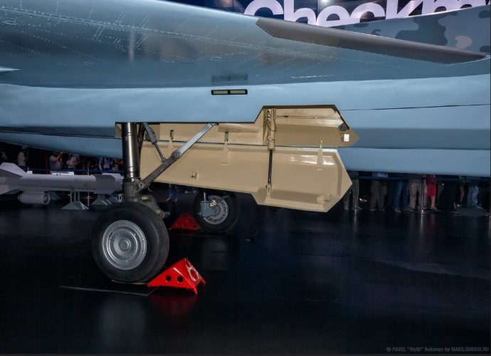
With the slanted fuselage and simple gear layout the YF-24 gear reminds me of the Su-75's gear placement.
 

Attachments

  • Su75.jpg
    Su75.jpg
    102.7 KB · Views: 140
  • Su75 main gear.jpg
    Su75 main gear.jpg
    137.9 KB · Views: 146
  • Su75 gear retraction.jpg
    Su75 gear retraction.jpg
    31.9 KB · Views: 176
Still quietly wrestling with this.

I have come to bit of an impasse though, in that I can't figure out how the undercarriage is supposed to work! I've attached a rough diagram of my best guess so far (with red and green representing up and down respectively), but that still means the gear has to swing through ~130 degrees which seems... unlikely.

Any advice or real world examples would be much appreciated!

(Of course the original drawings might be wrong or misleading)View attachment 779123
I think I'd go with the Su75 version. Minimal complexity, single axis/point of rotation. Much simpler to deal with.

What you've got pictured would probably be done with two axes/points of rotation. MLG leg pivots at the top, and a linkage attached to the airframe pivots the wheel inside the leg as the leg retracts.

Aviation design is all about "simplify, then add lightness"
 
The gear extend/retract cylinder (connected between the links) also functions as a downlock but the cylinder would have to have an internal mechanical lock as well (similar to business jets) to maintain downlock in the case of hydro system failure, and yes, keep it simple. If they went with this config, all they would need is a simple hydro uplock mechanism. The main gear door/door cylinder would be identical in relation to their functions.
 
The gear extend/retract cylinder (connected between the links) also functions as a downlock but the cylinder would have to have an internal mechanical lock as well (similar to business jets) to maintain downlock in the case of hydro system failure, and yes, keep it simple. If they went with this config, all they would need is a simple hydro uplock mechanism. The main gear door/door cylinder would be identical in relation to their functions.
With landing gear, I'd want the doors essentially powered by the unlock hydraulics or mechanical connections to the gear.
 
Ok so much later I decided that a) I wanted to finish this in 2025 and b) I do not have the right kind of brain to figure out the gear mechanism. If there are no obvious clangers I'll tidy this up for Sketchfab next.
 

Attachments

  • 04_beauty_top.png
    04_beauty_top.png
    726.9 KB · Views: 137
  • 04_beauty_bottom.png
    04_beauty_bottom.png
    679.1 KB · Views: 127
  • 04_beauty_rear.png
    04_beauty_rear.png
    901.4 KB · Views: 140
  • 04_orthographics.png
    04_orthographics.png
    1,003 KB · Views: 165
A few known / will not fix issues:
- The gear doors are a total invention
- The double chine is based on the wind tunnel model, rather than the drawings
- At some point the canopy shape has drifted
- Somehow lost the anhedral curve through the wings, good spot @lippischh
 
Last edited:

Similar threads

Back
Top Bottom