Atlas FCA-1 Carver fighter project

@ Graugrun,
I'm very confused about this sudden introduction of this new "variant" of the design. Pierre is a well connected person with many people that can verify that this is like swinging at a pinata, but you're at the wrong birthday party.

I have met him on a few occasions, hell of a nice guy. Also listened to some of his talks, and he is very knowledgeable and intriguing to listen to.

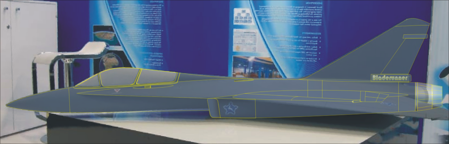
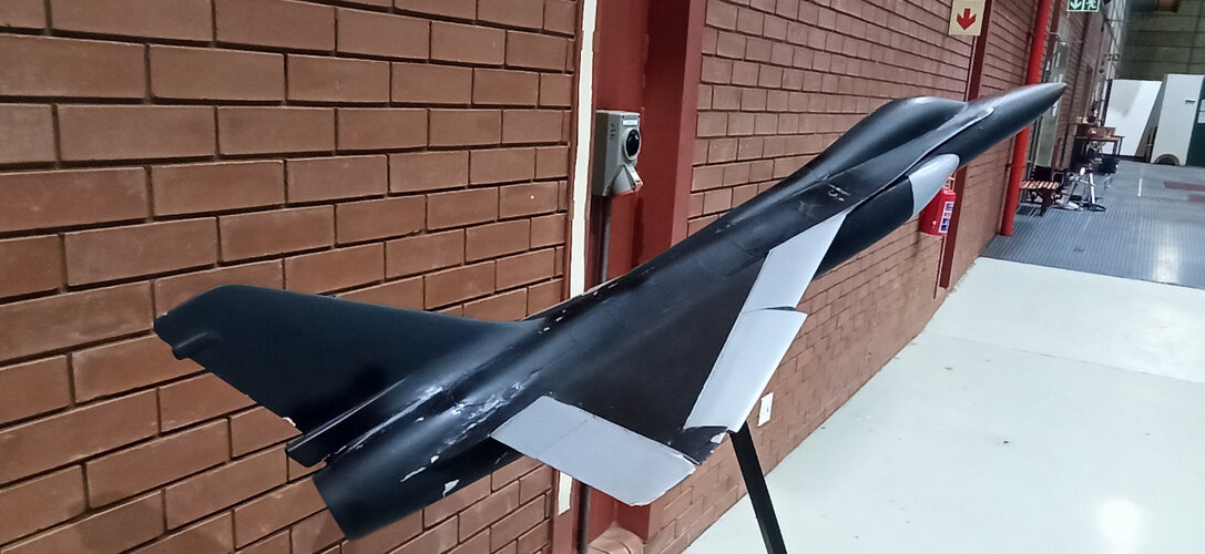
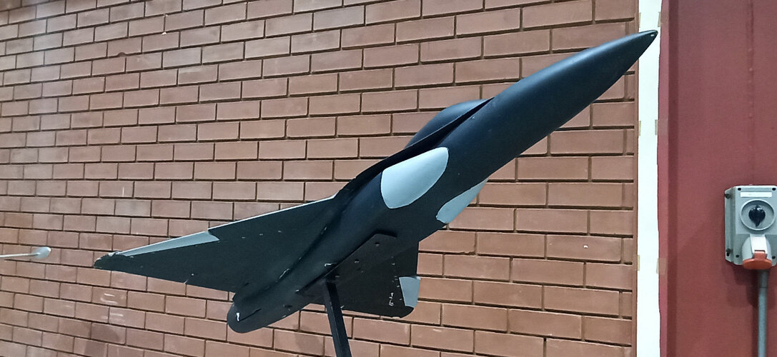
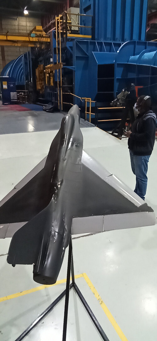
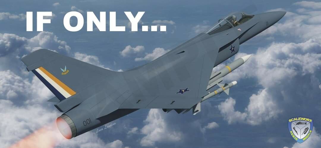
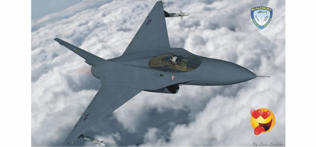
I can say with certainty that the mock up in the photo is true to the mid-mounted (almost shoulder-mounted) wing and two air intakes on the sides. Development halted on the single engine design after the twin engine designs were pursued, therefore funds and manpower would not have been allocated for further work on the single.

Cheers
 
Well more than anything I wanted to share this with you all (having sat on it for 5 years plus), and create some healthy debate around it - and of course PL-V would have his own ideas regards what he thinks was the end product (even though the mid-section should be very accurate according to the only public photo of the jig/mock-up thereof). I also tried to place in my own thoughts, comments and disagreements with his final image that he created for me, however is seems that some here have even more clear views of what it would have looked like..

Since none of us can openly produce verified and clear photos of the approved wind tunnel models/fully built mock-up, we're all just guessing (educated or not) to some or other degree. As stated I saw at least 5-6 at Atlas Aviation Carver many years ago (and walked around the two tables studying them for a while) - to date only two of them have become open knowledge via public photos. So which ones (the single engine & the twin engine) are the correct ones?

I do know at least 3 professional model makers in South Africa, two of whom made - (and one still makes) a large number of different models for the defence industry, I keep meaning to pay them a visit and take a good look through their back catalogues/photo files to see what I can find.

I am a little dissapointed though, as my clear understanding is that this site is very much about the discussion and attempt at finding out what was meant to be and what could have been that for many reasons remain secret to this day - unfortunately it seems that If have been a little mistaken in this particular case - perhaps I should just take some of the advice posted above.. "you're at the wrong birthday party"...

So I'll gracefully bow out of this one...
 
Last edited:
Good evening guys,

The mock up jig seems to have been a heated debate lately. The only real part on it, is the mid section where the landing gear would have been attached. Having the same profile, I suspect the former behind it might have resembled a second similar part, but with wing attachment points only. So I sharpened my pencil and crayons and did a few basic measurements, and worked in the ATAR 09-K50 dimensions. This also showed that I was mistaken about the function of the front former with with the two semi circle cutouts, and could not have been part of the air intake system, as they are too high up. The intake trunking would probably be S-shaped, and the illustration below is a big thumb sucked, eyeball Mk.1 guestimate and not fact. ;)

Cheers
 

Attachments

  • Airflow Forum.PNG
    Airflow Forum.PNG
    181.9 KB · Views: 547
@Graugrun

The debate here centered around the interpretation of the mock-up and PL-V's suggestion and sketch he produced just does not fit the mock-up photo which does match published drawings quite well. The single engine Carver seems to have been quite well defined - up to point where trial manufacturing started. Based on what has been discussed over the years, the drawings published in Winston Brent's Cheetah book still seem to be the most accurate representation of what a production single engine version would have looked like. This is confirmed by other unpublished drawings observed by members here.

So yes, this is an thread open for healty debate, but it is also a thread where discussion will disagree with some theories especially if there is little hard evidence for them based on the publically available material used as the source. Most of the other evidence for this project is little more than conversations with involved parties, observations and a couple of unpublished drawings so I doubt we will ever have a final answer though and there is plenty scope for debate - most of that around the twin engine variant.
 
Last edited:
As stated I saw at least 5-6 at Atlas Aviation Carver many years ago (and walked around the two tables studying them for a while) - to date only two of them have become open knowledge via public photos. So which ones (the single engine & the twin engine) are the correct ones?
I have seen at least 4 of them, and I drew up an illustration as best as my memory could serve me. Perhaps we have seen the same ones.

Cheers.
 

Attachments

  • Carver Models.PNG
    Carver Models.PNG
    605.9 KB · Views: 399
I have seen at least 4 of them, and I drew up an illustration as best as my memory could serve me. Perhaps we have seen the same ones.

Cheers.
Those are some really interesting designs, Bladerunner! That last one especially looks very interesting. Especially the intakes...! @Graugrun do you maybe recognise any of them?

All of them look very sleek - almost Sukhoi esque albeit without that massive droopy nose. Wonder what has happened to those models? Must either be in storage or already have ended up on the scrap heap after a clearing up...
 
All of them look very sleek - almost Sukhoi esque albeit without that massive droopy nose.
Black Mamba,
I thought the same, but I think once the single engine Carver has imprinted in one's mind, it is hard to not want to see something similar. I have placed the drawing of the twin engine, single seat, single tail fin over the model of the one that was "accidentally" displayed, and matches rather well.

That last one especially looks very interesting. Especially the intakes...!
Very unique and most certainly most extreme of them. Probably the last proposal in the line of models as well.

Cheers
 

Attachments

  • Overlay.PNG
    Overlay.PNG
    1.4 MB · Views: 389
Certainly it seems in most competent designs with LERX, the inlets are well behind the form. So this conforms to that trend.
 
Certainly it seems in most competent designs with LERX, the inlets are well behind the form. So this conforms to that trend.
That's correct, quite the trend. The later twin engined versions also have their wings mounted further aft. That last two seat, twin engine had the engine nacelles widely spaced and underslung in a similar fashion as on an F-14, as well as two tail fins.

Cheers
 
Last edited:
Certainly it seems in most competent designs with LERX, the inlets are well behind the form. So this conforms to that trend.
That's correct, quite the trend. The later twin engined versions also have their wings mounted further aft. That last two seat, twin engine had the engine nacelles widely spaced and underslung in a similar fashion as on an F-14, as two tail fins.

Cheers
Perhaps more relevant is the ECA design in the early 1980's during the negotiations over Eurofighter.
But certainly after the F14 the benefits of this approach were being examined in design houses around the world.
All in all the South Africans had a very competent approach to the design as far as I can see.
 
These have surfaced on the net - the Carver I lowspeed windtunnel model. Not the final Carver design but it was the one that got closest to actual flying hardware! Stunning looking design. Pity they didn't stick to this design and atleast got a prototype going...
 

Attachments

  • Carver model 1.jpeg
    Carver model 1.jpeg
    219.9 KB · Views: 288
  • Carver model 2.jpeg
    Carver model 2.jpeg
    228.8 KB · Views: 271
  • Carver model 3.jpeg
    Carver model 3.jpeg
    179.3 KB · Views: 331
Fantastic!

The door opens a little more...

This is the most official depiction or layout so far, even considering the 2 display models (single and twin engined models).

This though is an actual working, or rather, testing layout, as evidenced by the CSIR wind tunnel in the background.

I assume you found it over at the SAAF forum?

What a beautiful design.

Edit: I suspect this particular wind tunnel model concentrated on the wing leading edge, and perhaps different designs thereof.
From memory, there is a poster over at the SAAF forum who worked on the Cheetah ACW wing, as well as Carver, as an engineer, and stated that a cambered leading edge and slats was tested, amongst others, and gave very good results.
 
Last edited:
These have surfaced on the net - the Carver I lowspeed windtunnel model. Not the final Carver design but it was the one that got closest to actual flying hardware! Stunning looking design. Pity they didn't stick to this design and atleast got a prototype going...

Second picture is what you get when a Mirage 2000 and a Hornet have a one night stand.

Should we call that a Miret ? (mirettes is french slang for "eyes". "J'en ai pris plein les mirettes !" "I had the thrill of a lifetime !"

Alternative: "Horage" which sounds like "orage": "thunderstorm".
 

Attachments

  • mcdonnel_hornet.gif
    mcdonnel_hornet.gif
    90.4 KB · Views: 306
Last edited:
These have surfaced on the net - the Carver I lowspeed windtunnel model. Not the final Carver design but it was the one that got closest to actual flying hardware! Stunning looking design. Pity they didn't stick to this design and atleast got a prototype going...

Second picture is what you get when a Mirage 2000 and a Hornet have a one night stand.

Should we call that a Miret ? (mirettes is french slang for "eyes". "J'en ai pris plein les mirettes !" "I had the thrill of a lifetime !"

Alternative: "Horage" which sounds like "orage": "thunderstorm".
UM...Tejas is feeling bad
 
Second picture is what you get when a Mirage 2000 and a Hornet have a one night stand.

My thoughts exactly. I was about to post the same, then thought better of it, but thankfully you went a step further and actually mated the two. It's uncanny just how close that cut'n'paste job comes to the wind tunnel model. :cool:
 
Even more since I suck at drawing anything. I was lucky Aviastar had passable 3-views.
 
Bringing this thread back to topic of discussing Carver.

I came across this on FB. Looks like a perfect match for the posted model. The windtunnel model also confirms the available 3-view published in the Guardians Cheetah book as correct.

Pity we can't deduce much about the engine from the model other than it being "sizeable" with the Atar still being the leading candidate in my view.
 

Attachments

  • Carver_FB.jpg
    Carver_FB.jpg
    35.7 KB · Views: 275
The wing root / air intake / LERX combination is pretty interesting.

A good case could be make that Dassault, the Israelis and South Africa each went to different directions - starting from the exact same aircraft, the Mirage III.

-Dassault did not believe classic canards made sense on Mirage III / 2000 basic shape, essentially because the rounded intakes got in the way.
The intakes were also kind of too short to support a canard: it was too close from the wing: not "fore" enough. In that regard the Mirage 2000 intakes were a touch better than the Mirage III, but still too short, so it got strakes there.

-Milan worked around that issue with a foldable canard on the nose, but it wrecked the air flow into the intakes and had to be folded in the nose... heavy, complicated stuff.
- Mirage 2000 had small strakes and nothing more (atrophied canards !)
- Mirage 4000 had full blown canards in the end, with analog FBW
- Rafale was the next step: moving the air intakes downards and blend the canard with the cockpit sides

The israelis differed from Dassault opinion and put canards on the Kfir (Nesher didn't had them).
- Still Dassault didn't put canards on the Mirage 50...
- yet the Mirage III NG finally got them, also with analog FBW.
- Then every single late Mirage III upgrade in the 1980's had them: Pantera, Finger, Switzerland, South America, South Africa

South Africa somewhat went yet another direction for Carver. A bit like Rafale, they moved the air intakes downwards to get some room on the cockpit side. Yet instead of canard, they mated F-18 Hornet LERX to the Mirage delta wing.

My understanding is that Dassault found canards to be not very useful on the basic Mirage III / 2000 shape, with or without analog FBW - because the air intakes were in the way and the too short intakes had the canard hanged too close from the wing to fully exploit it.

Rafale moved the intakes out of the way and now the canard could more efficiently interact with the delta wing for more agility in air combat.
This is the exact reason of the biggest change in overall shape between the 4000 and Rafale. Somewhere on this forum is an "intermediate" 1980 step between the two, with intermediate air intakes.

It is quite remarquable the South Africans came to the same conclusion, same period as Rafale (mid to late 1980's) yet put F-18 LERX instead of Rafale "blended canard".
 
Last edited:
Bringing this thread back to topic of discussing Carver.

I came across this on FB. Looks like a perfect match for the posted model. The windtunnel model also confirms the available 3-view published in the Guardians Cheetah book as correct.

Pity we can't deduce much about the engine from the model other than it being "sizeable" with the Atar still being the leading candidate in my view.
What date was that posted on Fb?
Nice render.

I wonder where the author got the 3-view render from in the Guardians Cheetah book?

So far, I see nothing on the model originally exhibited, nor the 3- view, nor the wind tunnel model that shows airbrakes in the traditional location on the wing top surface as found on the Mirage III/Cheetah/Mirage 2000. This might be a function of the wing being in the upper mounted position.
I suspect either a Mirage F1 type location aft of the intakes ventrally, or, as shown on that render from FB, dorsally at the fuselage rear.
The upper mounted wing would also influence the main undercarriage location, and the 3-view from Guardians Cheetah shows what appears to be a single wheel fuselage retracting position for the main undercarriage, with twin wheel front undercarriage.

Edit: Nevermind.
The original display model shows the airbrakes dorsally, on the fuselage rear alongside the vertical fin and wing trailing edge, where one might logically expect them.
The person who did that render on Fb clearly had seen and used both the original display model, and this recently revealed wind tunnel model.
 
Last edited:
What date was that posted on Fb?
Nice render.
Very recently, shortly after the windtunnel model surfaced in the public sphere. Helps bring the model to life well!

Regarding the gear - the general consensus is something akin to the F1 undercarridge based on the wheel location as indicated on publicly available drawings.
 
This was a frankeinplane except done intelligently. Mirage III / 2000 with F-18 LERX and F-1 undercarriage.
 
This was a frankeinplane except done intelligently. Mirage III / 2000 with F-18 LERX and F-1 undercarriage.
It is well known that the design lead on the M2000 was also the design lead on Carver. I see it more as he had the chance of a clean sheet design having also now learnt from the M2000 what and where can be improved upon. South Africa would also have had their own unique set of design requirements that would have driven the design configuration. Good high alpha performance was clearly one of them.

I have written about it before on this forum but this team was basically designing an highly manuverable fighter they didn't have the engine for!
 
Last edited:
I think "frankenplane" does a disservice to thousands upon thousands of hours of highly skilled engineers using expensive infrastructure put in place to achieve a thorough stated design goal.
You have to reset or recheck your values against the User Requirement Document any time a change is made, no matter how small.
This was stated in the interview given in Cheetah: Guardians of the Nation, and is applicable to any well run programme.

They had the User Requirement, with stated goals, and had to test and retest ad infinitum as the programme progressed.
I know various aerodynamic layouts were looked at and studied, as I have seen what I strongly take to be a very early design Carver model, very much removed from the layout eventually chosen.

We have a fighter that clearly has stated goals, and the configuration drove that.
There is very little in common with the Mirage 2000 here. Not even the wing sweep angle.

I'm not sure people understand the complexities of proper aerodynamic research sometimes.
The engineer involved over at the SAAF forum alluded to this, when he stated that sometimes teams rely on the FBW system to help in an overall manner, instead of investing in the hard yards of refining properly the underpinning physical aerodynamic qualities.
He alluded to the fact that in Carver, great attention was given to the proper and through design and testing of the aerodynamic qualities needed.

Otherwise, a simpler "monkey see, monkey do" copy and paste approach would be seen.
 
Last edited:
With no drawings available or proper dimensions of the SMR-95 engine, I had to resort to ask assistance from a friend to measure the real McCoy. It's significantly shorter than the ATAR 09K50, and I made an illustration for comparison. The COG of the aircraft would have been quite a task to rectify.

20220523_231247.jpg
 
With respect the “teams relying on FBW” comment has its own layer of self-justifying/ self-deceiving pretence to it when considering that Carver was an ultimately unsuccessful footnote while FBW enabled fighter designs with relaxed stability etc. proliferated and became the new “standard” (even the F-15 eventually picked it up in the variants still in production).
 
With respect the “teams relying on FBW” comment has its own layer of self-justifying/ self-deceiving pretence to it when considering that Carver was an ultimately unsuccessful footnote while FBW enabled fighter designs with relaxed stability etc. proliferated and became the new “standard” (even the F-15 eventually picked it up in the variants still in production).
This is vastly oversimplifying the reasons for Carver's failure to result in flying hardware...

Perfecting the design to meet the URS while relying on FBW might have complicated the design to some degree, but it was not the main reason it failed to result in a flying prototype. Being a step too far for a still very fledgling industry isolated from most outside assistance is much closer to the truth.

Carver as a program existed from the mid 80's till very early 90's. 10 years at the most if we are being generous. In that time the country had to design and build wind tunnels, master advanced composite capabilities, advanced metalurigcal forging abilities etc. All things it took even super powers years to perfect. I'm no expert but those capabilities needed to be in place before Carver or any similar project beared fruit. Even with the country spending nearly 4% GDP on defence Carver was still predicted to only enter service by 2000. That spending started to drastically decrease by 1989 already as tensions ceased and the border conflict concluded. By 1991 Carver was toast and cancelled.

There is a whole fractoral of stepping stones that SA needed to master to build a 4th gen platform. And we are still ignoring designing and building a local engine fitting of the role! I don't think high refinement of the design for FBW sits high on the list for it failing to produce flying hardware...
 
Last edited:
With no drawings available or proper dimensions of the SMR-95 engine, I had to resort to ask assistance from a friend to measure the real McCoy. It's significantly shorter than the ATAR 09K50, and I made an illustration for comparison. The COG of the aircraft would have been quite a task to rectify.

View attachment 678372
Interesting comparison Bladerunner. Just a question though - given that Carver 1 was an Atar design first, is it not logical to assume that a switch to the SMR somewhere later in the project would have resulted in similar modifications than was done to the SMR converted Cheetah/F1 to maintain the original CoG of the design? i.e. SMR compressor face 600mm back from Atar position and new tailcone to link with SMR turkey feathers.
 
I never said the Carver was unsuccessful because of the lack of FBW.
The actual cause was the end of Apartheid South Africa (with the Carver being a product of that thankfully long gone context).

I was more referencing the comment that use of FBW by other more successful producers of more successful and superior fighter aircraft was somehow seen a “cheat” or “shortcut” when it’s non-use in this period of time was really an indication of a lack of comparable sophistication and capabilities versus those producers.
Earlier near-contemporaries like the F-15 and the MIG-29 didn’t have relaxed stability FBW configurations but it’s notable that their last production marks did evolve in this direction while more direct contemporaries of the Carver had this from the get-go.
 
Interesting comparison Bladerunner. Just a question though - given that Carver 1 was an Atar design first, is it not logical to assume that a switch to the SMR somewhere later in the project would have resulted in similar modifications than was done to the SMR converted Cheetah/F1 to maintain the original CoG of the design? i.e. SMR compressor face 600mm back from Atar position and new tailcone to link with SMR turkey feathers.
I agree, the airframe seems to be specifically designed for the ATAR 09K50, and airframe modifications similar to what was done on the Super F-1AZ and Super Cheetah D2 would have been inevitable.
 
The actual cause was the end of Apartheid South Africa (with the Carver being a product of that thankfully long gone context).
A big oversimplification... Huge dept, cripling sanctions and unsustainable war spending forced drastic defence cuts and a move to the negotiating table and ultimately democracy. By the early 90's there was a big fight for scare (compared to the previous decade) funding within Atlas. Rooivalk for example had a lot of influential figures in support and it was far more advanced in the design process with XDM already flying in Feb 1990. During this project rationlisation "era" Carver was axed. Things slowly kept declining after that as defence spending kept decreasing, but that but that is far outside the scope of this thread.

I don't want to push this thread into politics so I hope the line is drawn here, but I think understanding the defence situation, specifically the financial aspect thereof from the early 90's onwards within the SA defence sector is improtant to understanding why Carver and so many other local design projects remained mostly paper tigers.
 
Err.....??
Nobody said Carver didn't have FBW.
An engineer on the project I spoke to, as well as the design officer of the project, confirmed it DID have a FBW.
It was an integral and important part of the design brief. A central part of the User Requirement Document.

The engineer actually said that the FBW control system was not a particularly difficult part of the project.
He stated that a LOT of attention was paid to get the raw aerodynamic data and design on Carver correct. And that this was the correct, best-practice approach.
He then made an off-hand comment that sometimes engineers use fbw to smooth over such things, instead of putting the hard yards in. And he didn't particularly hold that practice in high regard.

This diversion comes from completely misconstruing and misunderstanding of what I wrote, I think.

Sheesh....
 
Last edited:
Amongst other points on Carver, this below is one of his points on the matter:

"No, a LERX does not necessarily imply FBW. However FBW was intended for Carver, and incidentally, I have just reestablished contact with one of the FBW people I used to work with, who is now in Italy. (everybody knows everybody else in this incestuous business
:wink:
) FBW is not as complicated as many make out. The real difficult part is getting the basic aerodynamics to give sufficient control effectiveness in all flight regimes. The electronics part is comparatively easy, so much so that too many aircraft companies rely on the control system rather than sorting out the raw aerodynamic problems."
 
Last edited:
Interesting comparison Bladerunner. Just a question though - given that Carver 1 was an Atar design first, is it not logical to assume that a switch to the SMR somewhere later in the project would have resulted in similar modifications than was done to the SMR converted Cheetah/F1 to maintain the original CoG of the design? i.e. SMR compressor face 600mm back from Atar position and new tailcone to link with SMR turkey feathers
Most likely. Adjusting airflow for the intakes would be another challenge...
Bottom one is slightly shortened at the rear, with the compressor face in line with the forward spar.

20220524_013843.jpg
 

Similar threads

Back
Top Bottom