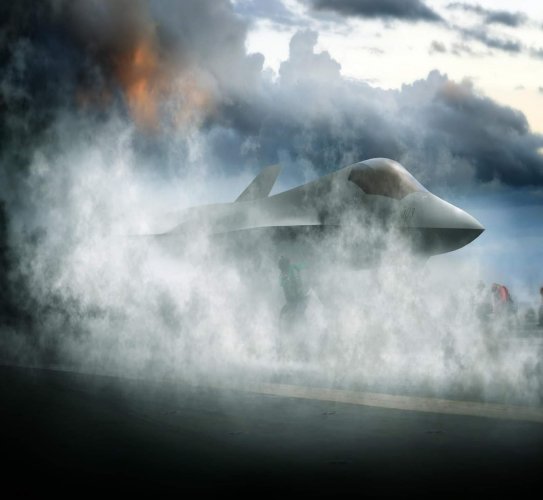
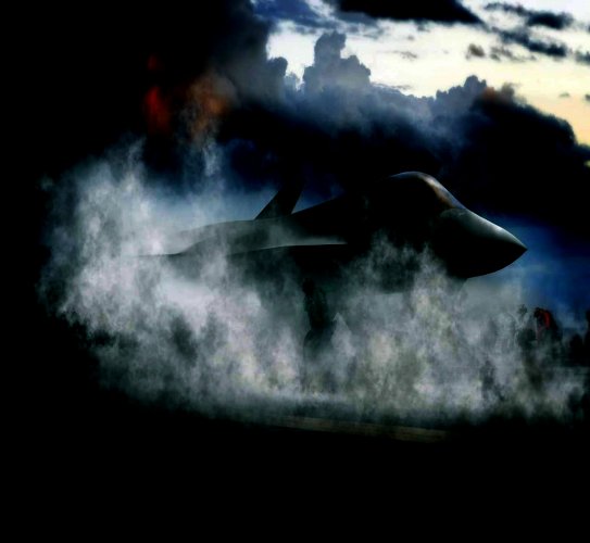
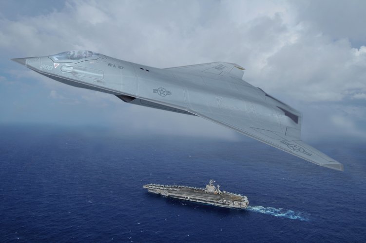
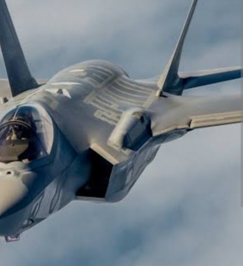
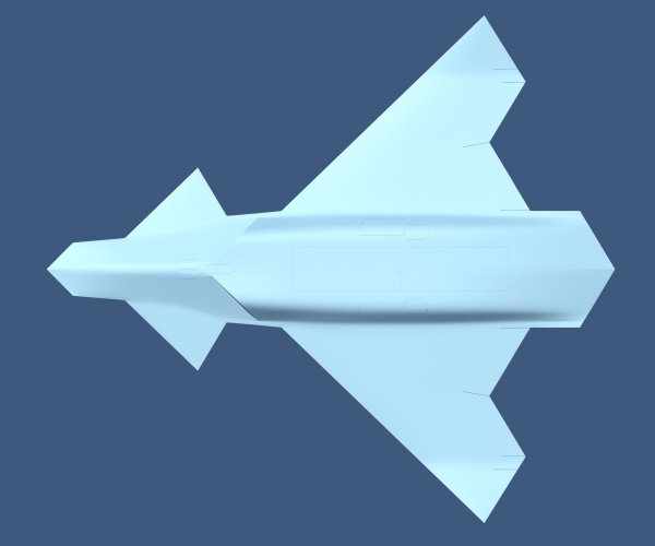
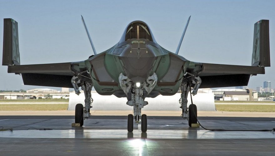
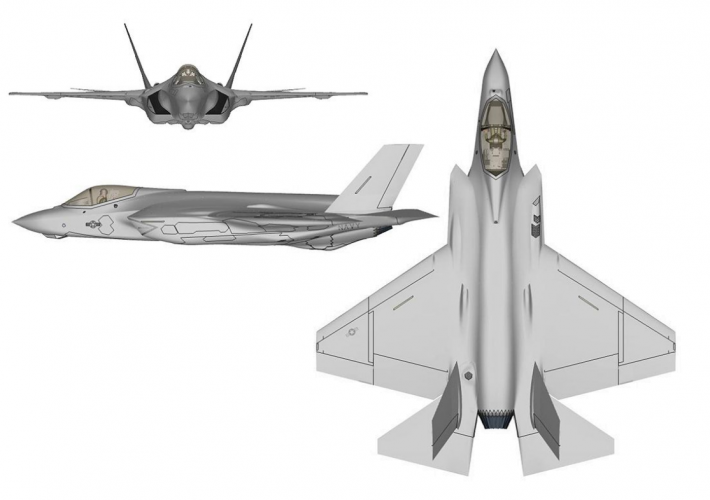
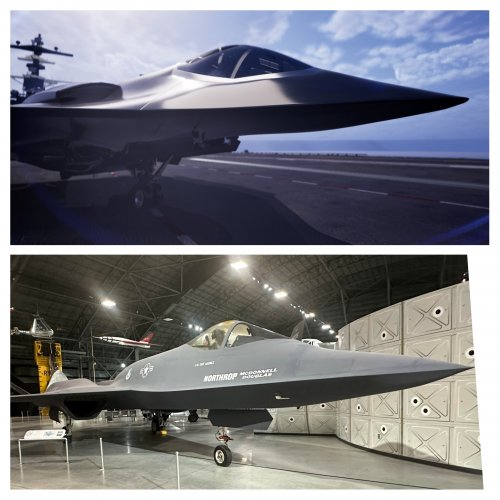
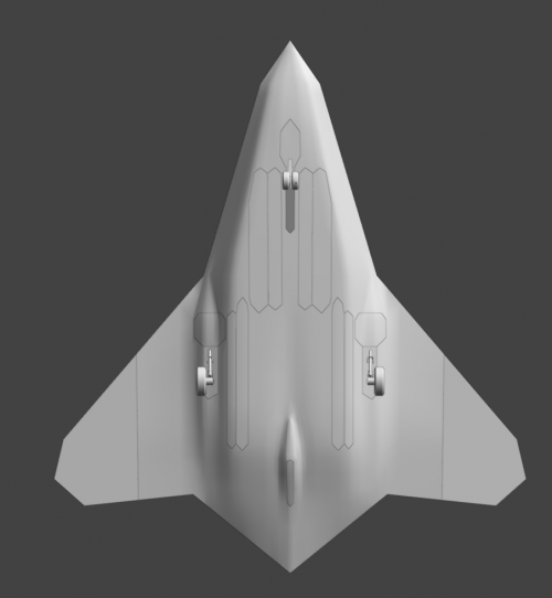
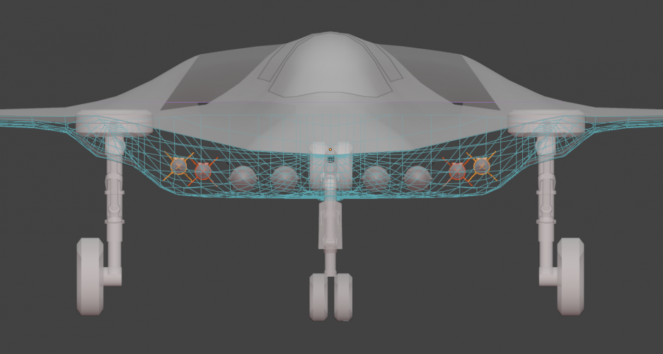
Artwork: possible configuration of the Northrop Grumman F/A-XX

View attachment 797932
I ended up using the same arrangement too. It's just a much more efficient use of volume than tandem bays. At only 81 m3, there's so much real-estate.
Looks good for a first draft!
I think IWBs for heavy / outsized payloads, like the JASSM depicted, should be positioned closer to the centre line. This would be beneficial from a structural point of view. Big cavities close to the wing root might be an issue, and the main landing gears have to go somewhere as well. Furthermore, for IWBs positioned close to the centre line, I would leave room for a "keel" in the middle.
 
Last edited:
View attachment 797932
I ended up using the same arrangement too. It's just a much more efficient use of volume than tandem bays. At only 81 m3, there's so much real-estate.

I think your's is more likely to be what that render shows though.

This planform seems to also fit together pretty well on the deck:

View attachment 797934
I still don't like how wide the fuselage ends up with side-by-side weapons bays, especially if we're talking 55-60" wide primary bays.

Your version with side bays for big hardware like AGM-158s, center bay for a 3rd AGM-158 or pair of SiAW, and then AAM bays seems to work tolerably well.
 
I laugh each time I see a F/A-XX rendering with intakes above the wing.
What makes you believe that a strike fighter/tactical bomber type aircraft, especially in the modern context, would prioritize aerial agility, high AoA maneuvers and the likes?

A low observable strike aircraft doesn't scream agile to me. And as F/A-XX is meant to replace the Super Hornets, it's intended to be a strike fighter first and being able to launch air-to-air missiles second.
 
What makes you believe that a strike fighter/tactical bomber type aircraft, especially in the modern context, would prioritize aerial agility, high AoA maneuvers and the likes?

A low observable strike aircraft doesn't scream agile to me. And as F/A-XX is meant to replace the Super Hornets, it's intended to be a strike fighter first and being able to launch air-to-air missiles second.
Except that the USN would be willing to accept a bigger RCS than the USAF will. So the intakes above the wing seem really odd for the FAXX. I would honestly expect them more for F-47, with the smaller RCS that comes with hidden inlets.
 
@VTOLicious
@Scott Kenny

I realized last night that the reinforcement bar behind the nose landing gear would interfere with truly centerline bays, so with what Ive designed at the moment has swollen up to 86m3 and im not entirely happy with it. Also im not sure it would make sense to carry LRASM and SiAW in the same load out. So it might end up as LRASM Or SiAWs in addition to 4 AAMs.

Regarding the top intakes, I guess it would also depend on what you want to hide from too. If you want to hide from ground targets, dorsal intakes makes sense. If you want to hide from high targets, ventral intakes make sense. NG ATA had dorsal intakes too.
 
Last edited:
Except that the USN would be willing to accept a bigger RCS than the USAF will. So the intakes above the wing seem really odd for the FAXX. I would honestly expect them more for F-47, with the smaller RCS that comes with hidden inlets.
But the USAF would prioritize maneuverability more over strike, this would make upper intakes undesirable to say the least. I think the USN could get away with top inlets for a supersonic striker, with limited air to air interception capabilities.
 
Looks good for a first draft!
I think IWBs for heavy / outsized payloads, like the JASSAM depicted, should be positioned closer to the centre line. This would be beneficial from a structural point of view. Big cavities close to the wing root might be an issue, and the main landing gears have to go somewhere as well. Furthermore, for IWBs positioned close to the centre line, I would leave room for a "keel" in the middle.
I know it's rarely used in most designs but there are publication on solutions using tube bars to enhance strength.
Most of the fuel will be locate above a horizontal center line (plane) so if the IWB are arranged such that they mainy occupy the lower half of a flying wing then all the main structures only need to be on that center plane, with the rest spreading out in a star like arrangement.
I still don't like how wide the fuselage ends up with side-by-side weapons bays, especially if we're talking 55-60" wide primary bays.

Your version with side bays for big hardware like AGM-158s, center bay for a 3rd AGM-158 or pair of SiAW, and then AAM bays seems to work tolerably well.
In most F/A-X renders and depictions the main IWB has been side by side and only a few have been tandam. It's 50/50 with published research models from everyone across the globe. I suppose the payload we are talking about isn't large enough to force a certain arrangement yet.
I would prefer them to be tandem in expectation of future "powered" stores needing the length. In theory the aerodynamic body with the "same" type of specific flight profile/performance scale up proportionally. But the length is just more dominating then the diameter.
But this is more a case for missile, hence, a more weighted consideration for the F47. Aside from the DEW allocation it's one main reason I prefered tandem bays for the F47.
The F/A-XX being more of a striker might need a bit of a longer bay for future stores (hypersonic cruise missile) but tandem isn't that needed. Though, the side bay that's exclusve for A2A I would want them to be tandem.
Chose your poison.
Except that the USN would be willing to accept a bigger RCS than the USAF will. So the intakes above the wing seem really odd for the FAXX. I would honestly expect them more for F-47, with the smaller RCS that comes with hidden inlets.
But the USAF would prioritize maneuverability more over strike, this would make upper intakes undesirable to say the least. I think the USN could get away with top inlets for a supersonic striker, with limited air to air interception capabilities.
I believe with 3-stream engine and their higher bypass volume pool temporary high AOA won't matter. For the same reason one engine stalling won't effect the other even if the intakes are next to each other. For the same reason they no longer pose a drag issue, rather they improve drag compared to older engines. The germans have published & presented that for their next gen fighter/drone engines (in Sweden). There are clear indication of aerodynamic solution that can help airflow. So I believe we are at a technological point where dorsal intakes are feasible.
 
Hello
This image from Northrop caught my attention. Compared to the model shown in their video, this image is much more "camouflaged." It has the typical haze used to hide sensitive parts of the aircraft.
Using Photoshop, I was able to find some interesting things: it appears to have curved top-mounted inlets, a rather angular or thick canard (similar to the F47). And finally, the canard and the wing's leading edge don't seem to coincide in height, with the wing being higher than the canard:
01.jpg 02.jpg 03.jpg
And obviously, this design has vertical tails in the style of the YF23, it seems.
I find it strange that this model is so hidden while the one in the video is shown without any hesitation.
From what I can see, this model would be considerably "lighter" than the one in the video, which looks like a very robust aircraft.
On another note, and apologies if this has already been discussed here: Could this patch represent a Navy demonstrator? I don't know much about patches and the texts they contain:

s-l1600 (15).png

But the shape of this aircraft, its curved rather than angular nose, seems perfect for placing upper air intakes, avoiding the vortices that the tips of an angular nose would generate.
Regards and thanks!
 
Last edited:
Hello
This image from Northrop caught my attention. Compared to the model shown in their video, this image is much more "camouflaged." It has the typical haze used to hide sensitive parts of the aircraft.
Using Photoshop, I was able to find some interesting things: it appears to have curved top-mounted inlets, a rather angular or thick canard (similar to the F47). And finally, the canard and the wing's leading edge don't seem to coincide in height, with the wing being lower than the canard:
I think that's just a very old generic render.
On TWZ, Northrop Grumman spokesperson confirmed that a previous concept artwork that reemerged on social media in recent days “is an old, generic rendering of a future Navy fighter that has been in the public domain for some time.”

There's also this NG concept back in 2015 NG 6th gen concept.jpg
 
Nice work.
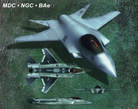
Alternatively, it could be a modified version of one of the JSF concepts:
jast_mdd_ng_bae_01.jpg

And the reason could be like how NG hid the F35 bottom with theirs. Who knows.
Dunno about the patch clearly dozens of planform types have been gone over with the ESAV effort allone.
 
Using Photoshop, I was able to find some interesting things: it appears to have curved top-mounted inlets, a rather angular or thick canard (similar to the F47). And finally, the canard and the wing's leading edge don't seem to coincide in height, with the wing being higher than the canard:
View attachment 798103
And obviously, this design has vertical tails in the style of the YF23, it seems.
Verticals, indeed.
Canards, maybe... But the wing being higher than the canard doesn't make sense at all.
Top inlets, hmm... If those are indeed air intakes, they would be very small. I can only imagine that they are recessed into the fuselage, in the style of the B-21 or MQ-25. But that wouldn't really fit with a supersonic aircraft.
 
Verticals, indeed.
Canards, maybe... But the wing being higher than the canard doesn't make sense at all.
Top inlets, hmm... If those are indeed air intakes, they would be very small. I can only imagine that they are recessed into the fuselage, in the style of the B-21 or MQ-25. But that wouldn't really fit with a supersonic aircraft.
Hi!

I adjusted the image in Photoshop. It seems to me that the air intake is wider. It reaches all the way to the fuselage. And from what I can see, it should have the same angle as the wing's leading edge in a plan view. That is, it wouldn't be the classic triangular, forward-pointing DSI-style air intake.
04.jpg 05.jpg

Something similar to what I'm doing with my new F-47 model. This is a view of the underside, and obviously with the air intakes on the upper part of the Northrop aircraft.

01.jpg


From what I see in the Northrop image, what I'm saying is that it would be something like what Lockheed showed in the air intakes of their NGAS, but located on the top of the aircraft.

1000120617.jpg
 
The F-35 also has a small bulge in the same location and its not an air intake.
Actually, the F-35C, the carrier version does have a small cooling inlet on its rightt shoulder. The renders clearly are larger in both enhenced view versions.
F-35C-wings-up.jpg F-35C_three-view.png

From what I see in the Northrop image, what I'm saying is that it would be something like what Lockheed showed in the air intakes of their NGAS, but located on the top of the aircraft.

View attachment 798136
Honestly, the version on NGAS makes less sense as it blocks airflow from the "bottom" (at AoA) the reason for ventral in the first place.
 
@VTOLicious
@Scott Kenny

I realized last night that the reinforcement bar behind the nose landing gear would interfere with truly centerline bays, so with what Ive designed at the moment has swollen up to 86m3 and im not entirely happy with it. Also im not sure it would make sense to carry LRASM and SiAW in the same load out. So it might end up as LRASM Or SiAWs in addition to 4 AAMs.
Agreed here. 4x LRASM or 4x SiAW (maybe 6x 2000lb)

Oh, right.

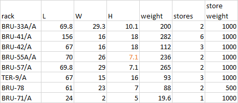
Does anyone have dimensions for a TER or MER? I'm wondering whether it'd be feasible to pack 12x500lb into the same volume as 2x LRASM without building custom racks.
 
Agreed here. 4x LRASM or 4x SiAW (maybe 6x 2000lb)

Oh, right.

Does anyone have dimensions for a TER or MER? I'm wondering whether it'd be feasible to pack 12x500lb into the same volume as 2x LRASM without building custom racks.
All new would be better but you asked for it:
Racks-MER-TER-0.png
 
Hi!

I adjusted the image in Photoshop. It seems to me that the air intake is wider. It reaches all the way to the fuselage. And from what I can see, it should have the same angle as the wing's leading edge in a plan view. That is, it wouldn't be the classic triangular, forward-pointing DSI-style air intake.
View attachment 798134View attachment 798135

Something similar to what I'm doing with my new F-47 model. This is a view of the underside, and obviously with the air intakes on the upper part of the Northrop aircraft.

View attachment 798137


From what I see in the Northrop image, what I'm saying is that it would be something like what Lockheed showed in the air intakes of their NGAS, but located on the top of the aircraft.

View attachment 798136
Yes good finding :D Is it me or I start to have a doubt about the tailless design of the 6th generation fighters ? When we look a the CCA all instead Lockheed Vectis have tails, and in this Northop FA/XX rendering it have tails too.
 
Yes good finding :D Is it me or I start to have a doubt about the tailless design of the 6th generation fighters ? When we look a the CCA all instead Lockheed Vectis have tails, and in this Northop FA/XX rendering it have tails too.

Keep in mind CCA are attritable as opposed to manned aircrafts. Manned aircrafts must have the best stealth production technology can offer.
The F/A-XX might have foldable elevons serving as verticals due to Navy requirement for landing control. Imho that's the most regression that could be acceptable.

How does the realism compare to DCS?
With no g-forces taking effect, awareness and piloting ability is questionable.
 
Hello
This image from Northrop caught my attention. Compared to the model shown in their video, this image is much more "camouflaged." It has the typical haze used to hide sensitive parts of the aircraft.
Using Photoshop, I was able to find some interesting things: it appears to have curved top-mounted inlets, a rather angular or thick canard (similar to the F47). And finally, the canard and the wing's leading edge don't seem to coincide in height, with the wing being higher than the canard:
There are plenty of alternate interesting configurations/planforms having long strakes including added small semi-canards/LEVCONS and bottom inlets that fit this rendering in Tony Chong's book. I don't quite understand also why put efforts in reconstructing old renderings when you have pretty new one that seemingly has something behind it due to efforts to mask shape. With these long strakes I see low chances/sense for top mounted inlets.
 
Last edited:
Hasn't this picture been identified as a photoshopped YF-23 one? Here or somewhere else, I can't remember?
 

Attachments

  • PhotoCollage_1768167758485.jpg
    PhotoCollage_1768167758485.jpg
    1.5 MB · Views: 119
How does the realism compare to DCS?
DCS is only realistic if you can write an EFM for it with reputable sources.

Flight model wise, how high fidelity you go is almost entirely reliant on how well you can implement and code stuff, but DCS isnt really a good place to try out a new planform as you have to write all the equations yourself and you are basically pumping numbers outside of the game for a solid.... say 4 years before this thing will be what you want it to be.
 
Last edited:
DCS is only realistic if you can write an EFM for it with reputable sources.

Flight model wise, how high fidelity you go is almost entirely reliant on how well you can implement and code stuff, but DCS isnt really a good place to try out a new planform as you have to write all the equations yourself and you are basically pumping numbers outside of the game for a solid.... say 4 years before this thing will be what you want it to be.
What about MSFS or X-Planes? (I haven't played around with any of them, I'm just curious if there are any that are close.)
 
Nice work.
Alternatively, it could be a modified version of one of the JSF concepts:
jast_mdd_ng_bae_01.jpg

And the reason could be like how NG hid the F35 bottom with theirs. Who knows.
Dunno about the patch clearly dozens of planform types have been gone over with the ESAV effort allone.
Except air intakes, a general look of the FCAS mock up.
 
View attachment 797939

Northrop Grummans proposal that we saw in their rendering. Scaled up from the carrier capable X-47B design that had a single F110 engines.

Length: 60 feet
Wingspan: 80 feet
Wingspan folded: 40 feet
MTOW: 100,000lb

I believe members have seen a sneak peak of the NG design and assumed it was the supersonic F/A-XX. It was probably their submission for the Long range strike program that is both in the Navy and USAF budget.

It is worth noting the X-47 Wikipedia page has the following

X-47C
Proposed larger version intended for the Navy's UCLASS project or as an Air Force strategic bomber

This could be the X-47C with a F-35 cockpit in front.
Air intakes over the frame is suitable only for a bomber or air attack. difficult for a fighter except if you avoid dog fight (this is why F22 is super agile and host a canon and 2 Sidewinder, just in case of, or if jamming is at a unparallel level, ie against China)
 
Are we also including the multirole UCAV intended to support the FAXX in this thread, or should we start another thread for that?
 
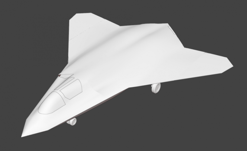
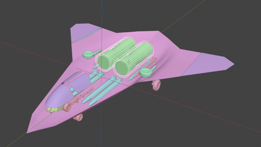
So I've managed to "fit" the missiles, wheels and engines into the airframe:
1768545162818.png
1768543491455.png
The center line will house the main arm(s) for the landing gear and its supports. On both sides of the centerline sit the strike weapon bays - either 2 SiAW or 1 LRASM per bay. The AAMs sit next to the engine and the landing gear sits in the wing root fairing. What you see for engines are F110-129s and the wireframe is the keep out zone that is 6 inches thick to represent the alotted space for the airframe bulkheads that fix the engine in place.

Overall, the plane itself looks spacious enough, but the weapon bays still makes me uncomfortable with clearances:
1768543764434.png
The distance between the strike weapon bay and the side AAM bays is 4 inches assuming that the doors match the bay width exactly. The distance between the AAM bays and the gear door is only 2 inches. The AAM bays also span the "curve" of the fuselage, which may or may not be problematic for structural reasons. You can also tell that the spacing for the AAMs may be too little even when staggered. Finally, the AAMs are pretty deeply buried due to the aft curvature of the aircraft (though I could just tilt them forward).
1768546649280.png
As it stands:

length is 16.9m
width is 15m
Volume: 85m3
Fuselage width is 5.8m

The F110-129s are 156in x 46.3 x 46.3 with an additional keep out zone of 12 inches in diameter.

The wheels used are 36 x 11.5 - 18 wheels. I found some sources for F-15E wheel sizes around 36 inches. I went with 36 inches since we are going for a higher MTOW up to 80k lbs.

The airframe still feels a little small to fit everything comfortably in the current layout and would be less tight with added length.

If anyone's got any ideas on how to better arrange the weapons or regarding the airframe itself, do tell. My main concern is whether I've left enough space to accommodate the un-depicted gear mechanisms, whether or how they interfere with the weapon bays. Also - 1 seater or 2 seater?
 
Last edited:
The airframe still feels a little small to fit everything comfortably in the current layout and would be less tight with added length.
It does.

what would a 5% OML stretch look like? Yes, I know that is a 16% weight increase.


If anyone's got any ideas on how to better arrange the weapons or regarding the airframe itself, do tell.
Would reversing the placement of AAMs and SiAW help?


My main concern is whether I've left enough space to accommodate the un-depicted gear mechanisms, whether or how they interfere with the weapon bays.
Gear mechanisms are packed into the bays. The main gear architecture you've chosen looks like F-14, I'd grab one of the close-up photo books to see how the actuators fit into the main bays.

IIRC the Hornet's nose gear folds the same way you've drawn, though I'd use Super Bug not Legacy (difference is probably 10% increase in girth)


Also - 1 seater or 2 seater?
2 seater, IMO. 1 pilot, 1 running the drones.
 
So I've managed to "fit" the missiles, wheels and engines into the airframe:

View attachment 798655
Overall, the plane itself looks spacious enough, but the weapon bays still makes me uncomfortable with clearances:
View attachment 798658
View attachment 798668
As it stands:

length is 16.9m
width is 15m
Volume: 85m3
Fuselage width is 5.8mū

The airframe still feels a little small to fit everything comfortably in the current layout and would be less tight with added length.

If anyone's got any ideas on how to better arrange the weapons or regarding the airframe itself, do tell. My main concern is whether I've left enough space to accommodate the un-depicted gear mechanisms, whether or how they interfere with the weapon bays. Also - 1 seater or 2 seater?
You could try swapping the main landing gear bays with the AAM bays.
When retracting the landing gear, the wheel wouldn't need to rotate 90° and would fit into a narrower bay then (next to the engine).
However, for structural reasons, the AAM bays should be positioned so that they only occupy space beneath the wings.
I think you could also size the AAM bays so that they either accommodate 2 AMRAAM (stacked) or 1 SiAW.
 
Also - 1 seater or 2 seater?
I think a two seater is the way to go, given we're leaning into a strike fighter/tactical bomber direction it makes sense with regards to distribution of workload. Additionally the coordination of unmanned aircraft comes to mind, although I'm curious how much autonomy and ship-based control will factor into that side of things. Lastly the Navy has a fondness for two seat aircraft, F-4, F-14, A-5, F/A-18D, F/A-18F.

With regards to the airframe, I like how you enclosed the WSO. It reminds me of the A-5 again, as well as the MiG-31 and some representatives of the Blackbird family. But I think you could actually make the windows even smaller, like they were on these aircraft, or actually ditch them entirely. Something one could irl justify with concerns about signature reduction and the quality of modern sensors and displays making the windows redundant for the second crewman.
 
I don't know if there's gonna be an NG concept thread but since it's F/A-XX I'll post here @Scott Kenny :

2 LRASMs + 4 AAMs

4 SiAW + 4 AAMs

2x F110-129 or derivatives.

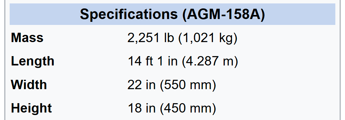
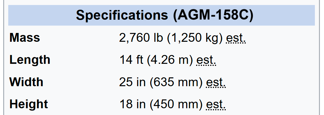
I just had a look at AGM-158 A / C specs... Is LRASM really shorter, but 3" wider than JASSM?

Source Wikipedia:

WikiSpecs_AGM-158A JASSM.png
WikiSpecs_AGM-158C LRASM.png

Btw:
14 ft 1 in = 4293 mm
22 in = 559 mm
18 in = 457 mm

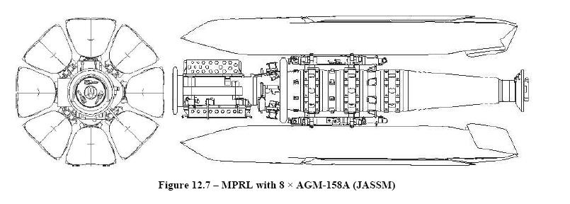
EDIT: Does anyone know the length of the Multi-Purpose Rotary Launcher (MPRL)? That would help with determining JASSM dimensions. Alternatively, a precise/scale three-view drawing would be very helpful ;)
JASSM_000.png
Pic source @lantinian : https://www.secretprojects.co.uk/threads/fb-23.2909/post-23783
 
Last edited:
AFAIK A, B, and C have the same form factor. C is specifically built off a B model. I had thought there were no changes in dimensions from A to B either, though there are a lot of internal changes including the engine.
 
Back
Top Bottom