
You are using an out of date browser. It may not display this or other websites correctly.
You should upgrade or use an alternative browser.
You should upgrade or use an alternative browser.
Area Rule - graphic method
- Thread starter [user-BG]
- Start date


Welcome to the forum!
Nice drawing! However, what is the method? Can you elaborate?
Nice drawing! However, what is the method? Can you elaborate?
Hi,
Really cool! I would love to see this style of diagram for the first-generation of jets. Are you using a dedicated software for the diagrams?
Regards,
Henning (HoHun)
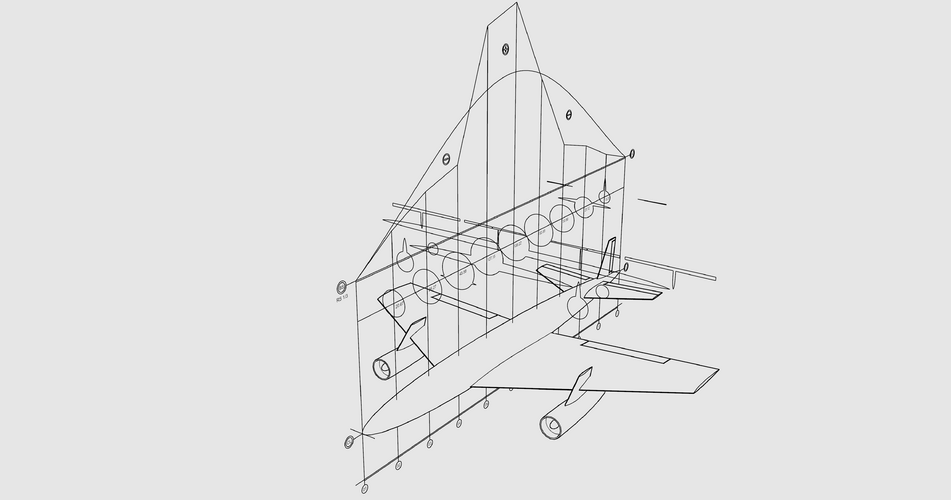
So let me introduce you a Area Rule's graphic method.
There is no double & triple integrals or some complex mathematics with no shape representation in the end.
Any comments welcome")
Really cool! I would love to see this style of diagram for the first-generation of jets. Are you using a dedicated software for the diagrams?
Regards,
Henning (HoHun)
Yup. For supersonic area rule, the cross-sections areas are measured via Mach plane cuts, with Amax biased to the rear based on your desired optimal Mach number.

[user-BG]
ACCESS: Restricted
Hello & thanks for reply.
When I introduced this method I have't idea of OpenVSP.
Please pay attention to the slopes of your curves and fact you have 2 peaks. This design is far away from perfect.
Also decreasing/increasing one section you'll have wavy surfaces, adding details just to fill gaps in the curve is also not the greatest idea ...
I passed through all this.
I'm achieving perfect smooth one peak curve from first try following one simple rule.
Regards
Attachments
Last edited:

[user-BG]
ACCESS: Restricted
Hello and thanks for you kindness!Welcome to the forum!
Nice drawing! However, what is the method? Can you elaborate?
Area Rule from Wikipedia (in History part there is a some objective information): https://en.wikipedia.org/wiki/Area_rule
Regards
[user-BG]
ACCESS: Restricted
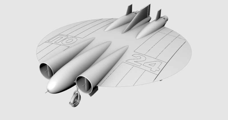
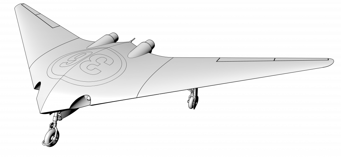
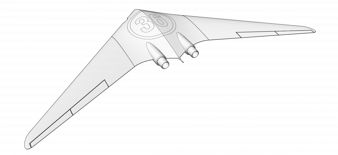
Here I decide to broke some of the rules of my method, just to see what will happens (model is built from the drawing found in the web).
Please note I performing exactly Area Rule just like it is done back in 40s, not something else!
I don't know what some software is doing, how it doing, how much it depend on a mesh errors ... etc. This is not subject of my research at all!
This is the result for today (first one is transparent background png):

Regards
Please note I performing exactly Area Rule just like it is done back in 40s, not something else!
I don't know what some software is doing, how it doing, how much it depend on a mesh errors ... etc. This is not subject of my research at all!
This is the result for today (first one is transparent background png):


Regards
[user-BG]
ACCESS: Restricted
Hello and thanks for reply, to be honest I thought the sameYou might change the vertical grid to red or green to separate it from the background.
... I'll! Job is not done yet ...


Takes me back to the start of my career. We had a little program to get the wave drag from the area distribution, but the drawings were still done by hand and I spent a lot of time with a planimeter actually getting those area distributions to input. Things soon got easier when the wing geometry was digital and I only had to measure the fuselage, but it was quite a time before the whole aircraft was digital.
[user-BG]
ACCESS: Restricted
Hello gwiz,Takes me back to the start of my career. We had a little program to get the wave drag from the area distribution, but the drawings were still done by hand and I spent a lot of time with a planimeter actually getting those area distributions to input. Things soon got easier when the wing geometry was digital and I only had to measure the fuselage, but it was quite a time before the whole aircraft was digital.
thank you so much for your comment. I'm glad somebody that spent time on Area Rule can appreciate/understand my idea. The point with software is that you never know what/how exactly it calculate. Also I prefer to have full control over 3d model, parametric packages are not my type, I'm into old school nurbs modeling.
Best regards.
Scott Kenny
ACCESS: USAP
Question for you, since I don't have enough of an engineering background to understand much of the area rule other than "it's needed."Takes me back to the start of my career. We had a little program to get the wave drag from the area distribution, but the drawings were still done by hand and I spent a lot of time with a planimeter actually getting those area distributions to input. Things soon got easier when the wing geometry was digital and I only had to measure the fuselage, but it was quite a time before the whole aircraft was digital.
@[user-BG]'s method puts the area change into a nice smooth curve if the area ruling is done correctly. Is there some optimum shape to this curve that you can express as a math formula? (basically working backwards from this formula to make the plane shape)
Yes, look up Sears-Haack body.
Scott Kenny
ACCESS: USAP
It's not sounding like that's what I meant.Yes, look up Sears-Haack body.
My question was if there was a mathematical description of the change in cross-sectional area that was considered ideal, not the body shape directly. Also, apparently the Sears-Haack body doesn't apply at transonic speeds, because the Prandtl-Glauert Equation is invalid there.
The method was applied to the cross-sectional area distribution using cutting planes tangential to the Mach cone and averaged over roll angle around the cone. If there was a difference between area at the nose and tail, eg a blunt base like a rocket, the Von Karman ogive between nose and tail was subtracted leaving a distribution pointed at both ends. The optimum shape for the residual area distribution was the Sears-Haack one, but the actual wave drag was calculated from the formula, the double integral one, in the Wikipedia entry for Sears-Haack. As the formula uses the second derivative of the area distribution, it is highly sensitive to the smoothness of the distribution.@[user-BG]'s method puts the area change into a nice smooth curve if the area ruling is done correctly. Is there some optimum shape to this curve that you can express as a math formula? (basically working backwards from this formula to make the plane shape)
In the transonic region, the equations describing the flow are a lot more complicated than in pure subsonic or supersonic flow and you need a full CFD method to get good predictions.
afcivileng
I really should change my personal text
Can you import an F102 and then an F106 to highlight the effect on essentially the same design
Scott Kenny
ACCESS: USAP
Ugh. Way over my math paygrade (I didn't do so well in Calculus, though I didn't find it all that hard. Just didn't do anywhere near enough problems to internalize the formulas.)The method was applied to the cross-sectional area distribution using cutting planes tangential to the Mach cone and averaged over roll angle around the cone. If there was a difference between area at the nose and tail, eg a blunt base like a rocket, the Von Karman ogive between nose and tail was subtracted leaving a distribution pointed at both ends. The optimum shape for the residual area distribution was the Sears-Haack one, but the actual wave drag was calculated from the formula, the double integral one, in the Wikipedia entry for Sears-Haack. As the formula uses the second derivative of the area distribution, it is highly sensitive to the smoothness of the distribution.
Bugger.In the transonic region, the equations describing the flow are a lot more complicated than in pure subsonic or supersonic flow and you need a full CFD method to get good predictions.
Scott Kenny
ACCESS: USAP
Second this!Can you import an F102 and then an F106 to highlight the effect on essentially the same design
[user-BG]
ACCESS: Restricted
Hello and thanks for the interest on my topic.Question for you, since I don't have enough of an engineering background to understand much of the area rule other than "it's needed."
@[user-BG]'s method puts the area change into a nice smooth curve if the area ruling is done correctly. Is there some optimum shape to this curve that you can express as a math formula? (basically working backwards from this formula to make the plane shape)
If I understand you right (since English is not my native language) you are asking for mathematical prescription of a optimum section distribution curve.
It is called "Normal Distribution" or "Gaus-Laplace distribution" or "Laplace distribution" in English.
Specially for you I attaching a picture and pdf with method formulas.
The method I introduced is simple and effective and can be converted into software package.
Regards

Attachments
[user-BG]
ACCESS: Restricted
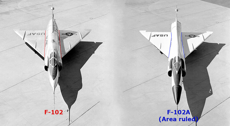
Hello, thanks for reply.Can you import an F102 and then an F106 to highlight the effect on essentially the same design
Please pay attention to the tubes of both planes - sections where wings are decreased just because of Area Rule.
However, I think a lot of things can be improved in those planes also on a lot of existing planes build in hundreds.
Regards
Hello, thanks for reply.
Please pay attention to the tubes of both planes - sections where wings are decreased just because of Area Rule.
However, I think a lot of things can be improved in those planes also on a lot of existing planes build in hundreds.
Regards
Attachments
[user-BG]
ACCESS: Restricted
Hello VTOLicious & other guys, thanks for replies to everybody.
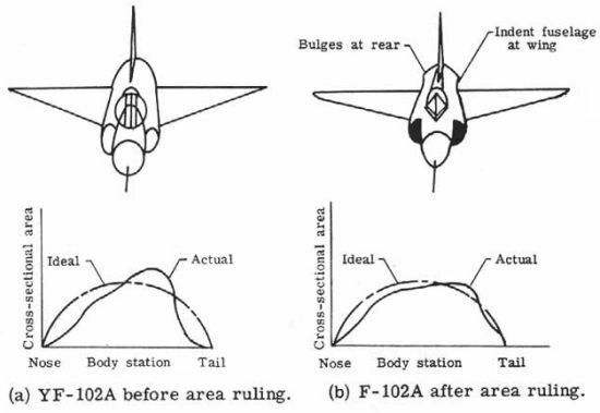
Great examples for F-102 modifications based on Area Rule.
What we can see is that even modifications result is 2 peaks curve.
Without being into American airplane designs a lot, I think Convair XF-92 is also representation of Area Rule.
Plane look (95%) like this:

Regards
Great examples for F-102 modifications based on Area Rule.
What we can see is that even modifications result is 2 peaks curve.
Without being into American airplane designs a lot, I think Convair XF-92 is also representation of Area Rule.
Plane look (95%) like this:

Regards
[user-BG]
ACCESS: Restricted
... and Area Rule for the Convair XF-92, two peaks again - at section 04 and even more in section 09. Please note linear segments representing section's area are decreased 100 times.
Convair XF-92 is great design, just mentioning Alexander Lippisch is enough .
... all comments welcome.
Regards
Convair XF-92 is great design, just mentioning Alexander Lippisch is enough
.


... all comments welcome.
Regards
Last edited:
richiebogie
ACCESS: Restricted
Hi. You mention that the normal distribution is the optimal curve for the area rule.
However this article says the semicircle is optimal:

 teamarcis.medium.com
It looks like a bit less than a half circle.
If you want to keep the second derivative low, then it would make more sense to use a quarter circle and start with the gradient of the surface area curve at 1 and ending at -1.
Another alternative could be a half sine curve from 0 to pi/2.
Eg. For an airplane of length L, the cross-sectional area would follow f(x) = sin(pi*x/2L) for x = 0 to L
Or it could be a full sine curve from -pi/2 to 3*pi/2.
Eg. For an airplane of length L, the cross-sectional area would follow f(x) = 1/2sin(2pi*x/L-pi/2) +1/2 for x = 0 to L
Most of these options suggest a short and stumpy plane is optimal, a bit like an NFL football.
Where did you get the idea for a normal distribution? Was this from a journal?
It would be interesting to see how each of these options changes your designs!
However this article says the semicircle is optimal:
The Transonic Area Rule
In the early 1950s, a few years after Chuck Yeager broke the ‘Sound Barrier’ using the rocket powered Bell X-1, American aerospace…
It looks like a bit less than a half circle.
If you want to keep the second derivative low, then it would make more sense to use a quarter circle and start with the gradient of the surface area curve at 1 and ending at -1.
Another alternative could be a half sine curve from 0 to pi/2.
Eg. For an airplane of length L, the cross-sectional area would follow f(x) = sin(pi*x/2L) for x = 0 to L
Or it could be a full sine curve from -pi/2 to 3*pi/2.
Eg. For an airplane of length L, the cross-sectional area would follow f(x) = 1/2sin(2pi*x/L-pi/2) +1/2 for x = 0 to L
Most of these options suggest a short and stumpy plane is optimal, a bit like an NFL football.
Where did you get the idea for a normal distribution? Was this from a journal?
It would be interesting to see how each of these options changes your designs!
Last edited:
[user-BG]
ACCESS: Restricted
Hello richiebogie,Hi. You mention that the normal distribution is the optimal curve for the area rule.
However this article says the semicircle is optimal:
The Transonic Area Rule
In the early 1950s, a few years after Chuck Yeager broke the ‘Sound Barrier’ using the rocket powered Bell X-1, American aerospace…
It looks like a bit less than a half circle.
If you want to keep the second derivative low, then it would make more sense to use a quarter circle and start with the gradient of the surface area curve at 1 and ending at -1.
Another alternative could be a half sine curve from 0 to pi/2.
Eg. For an airplane of length L, the cross-sectional area would follow f(x) = sin(pi*x/2L) for x = 0 to L
Or it could be a full sine curve from -pi/2 to 3*pi/2.
Eg. For an airplane of length L, the cross-sectional area would follow f(x) = 1/2sin(2pi*x/L-pi/2) +1/2 for x = 0 to L
Most of these options suggest a short and stumpy plane is optimal, a bit like an NFL football.
Where did you get the idea for a normal distribution? Was this from a journal?
It would be interesting to see how each of these options changes your designs!
thanks for comment on a topic.
In anglo saxon sources, this method is known as "Witcomb Area Rule", in reality this guy Witcomb at least 10 years later, did not achieve much even with huge amount of money he got available
.Area Rule belong to German Scientist/Mathematician Mr. Otto Frenz only! Mr. Frenzl visited states back in mid 40s and explain idea of the method to americans.
Credibility of anglo saxon sources for me is not so high.
Especially when we know that some institutuions in states after 1947 got official "policy of liying and denying".
Also note this article is written by journalist, not scientist.
However, link with higher credibility for me: https://aerospaceweb.org/question/aerodynamics/q0104.shtml
We have Normal Distribution:

PDF on a topic also attached here we got also Normal Distribution.
Just thinking, probably curvature of the Normal Distribution can be modified/deformed, but for me half circle is too much ...
Interesting what other guys here thinking and have to say
.Regards
Attachments
Last edited:
[user-BG]
ACCESS: Restricted
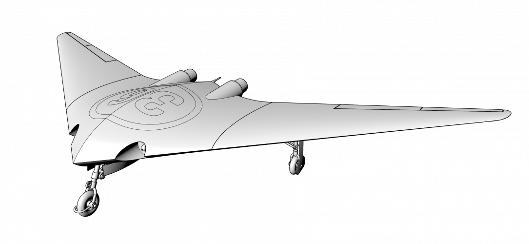
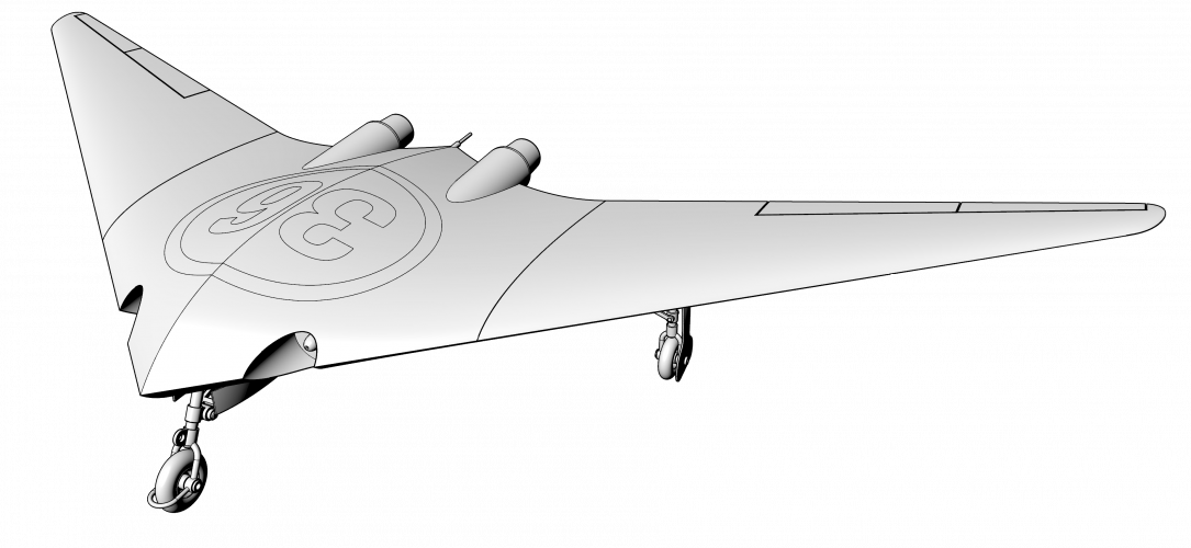
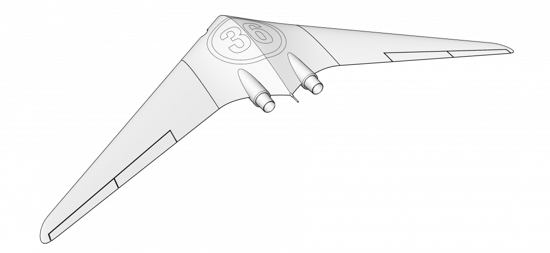
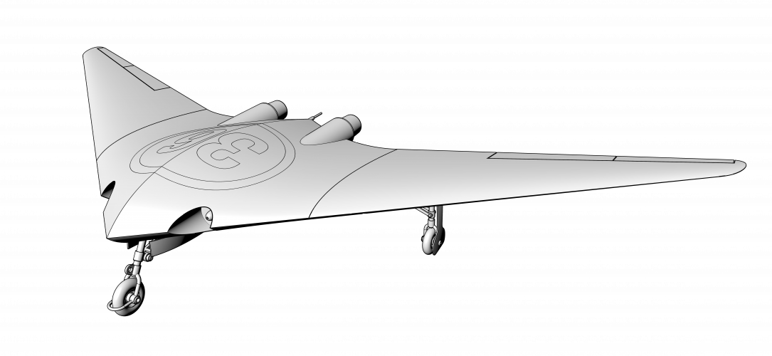
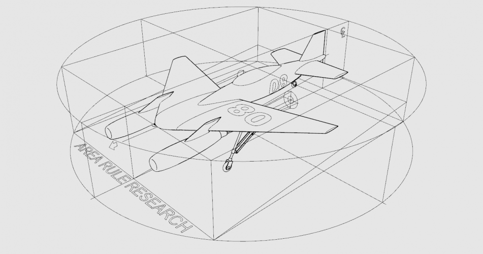
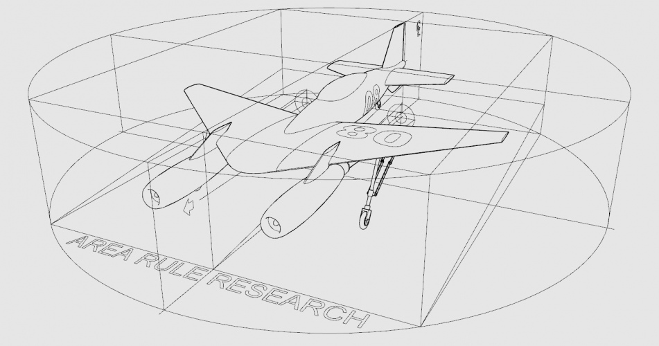
One more design - blend wingtips and tail.
360 degrees loop animation link: https://i.ibb.co/DT9RBrx/36-08E01.png (15.3mb - file too big to be posted here).
Regards
360 degrees loop animation link: https://i.ibb.co/DT9RBrx/36-08E01.png (15.3mb - file too big to be posted here).
Regards
Attachments
-
 2-ViewCapture20240329_163843.png308.2 KB · Views: 7
 -
 2-ViewCapture20240329_164050.png371.1 KB · Views: 5
 -
 2-ViewCapture20240329_164300.png247.7 KB · Views: 4
 -
 5-ViewCapture20240329_163912.png1.7 MB · Views: 3
 -
 5-ViewCapture20240329_164035.png1.9 MB · Views: 3
 -
 5-ViewCapture20240329_164313.png1.3 MB · Views: 3
Last edited:
[user-BG]
ACCESS: Restricted
... and something I tried years ago, directly from the Junkers patent drawing from 1944 (variant Abb.6). representing Area Rule.

Results was not great for me to be honest ... however I do understand I miss something in whole picture and changed my way of thinking/working.

Results was not great for me to be honest ... however I do understand I miss something in whole picture and changed my way of thinking/working.
Attachments
Better still, the YF-102 and F-102A.Can you import an F102 and then an F106 to highlight the effect on essentially the same design


Scott Kenny
ACCESS: USAP
Another example would be the F-8 Crusader and the Crusader flying the Supersonic Supercritical Airfoil. The Crusader SSA got some cheek and it looks like "hip" panels to further smooth out the Area Ruling that you can see pretty clearly in this photo:
The cheek panels are pretty obvious, the "hip" panels are a lot less obvious. Look at the bottom of the stabiliator, a line is visible swooping down and forward towards the belly and then comes up basically at the trailing edge of the wing.

The cheek panels are pretty obvious, the "hip" panels are a lot less obvious. Look at the bottom of the stabiliator, a line is visible swooping down and forward towards the belly and then comes up basically at the trailing edge of the wing.
[user-BG]
ACCESS: Restricted
Hello guys,
thanks for comments and nice pictures.
As I said above "Convair XF-92 is great design", but it is tube and wings type of plain - too much parameters to control and too much combinations of sizes and parts locations.
Lets not shift focus on a topic with details about planes already built back in time.
Lets focus on a presence and what we can do in a future - hope you did not mind .
What if I tell you, that I alone can design an airplane for something like 30 mins. and to get perfect Area Rule every time I try?
I'm not using any specific and expensive software .
To make things even more interesting I'll post 1st easiest and simple method.
What I'm expecting from you is to try to understand what I have done.
So your comments are welcome .
Lets dive in conspiracy theory ... that actually works:


... and one more additional hint image, pay attention to the root of the all digits.

I don't think it is hard task for you guys, but good luck guessing
Regards
thanks for comments and nice pictures.
As I said above "Convair XF-92 is great design", but it is tube and wings type of plain - too much parameters to control and too much combinations of sizes and parts locations.
Lets not shift focus on a topic with details about planes already built back in time.
Lets focus on a presence and what we can do in a future - hope you did not mind
.What if I tell you, that I alone can design an airplane for something like 30 mins. and to get perfect Area Rule every time I try?
I'm not using any specific and expensive software
.To make things even more interesting I'll post 1st easiest and simple method.
What I'm expecting from you is to try to understand what I have done.
So your comments are welcome
.Lets dive in conspiracy theory ... that actually works:


... and one more additional hint image, pay attention to the root of the all digits.

I don't think it is hard task for you guys, but good luck guessing
Regards

Similar threads
-
-
 Design Challenge: Lightweight Multirole Fighter (LMF)
- Started by VTOLicious
- Replies: 506
-
-

-
 AVIATION ART: "The Chicken Works" presents the first of many aviation art prints
- Started by Sentinel Chicken
- Replies: 9