The leading edge is probably a suboptimal location for radar: there is minimal vertical room to shrink the beam vertically, which might result in suboptimal gain… EW antennas are definitely doable on the leading edge though, the F-35 has them.Access panels for the big fecking antennas hiding in the leading edges. Whether for EW systems or LPI radars. or both.

You are using an out of date browser. It may not display this or other websites correctly.
You should upgrade or use an alternative browser.
You should upgrade or use an alternative browser.
Northrop Grumman B-21 Raider (LRS-B)
- Thread starter TomS
- Start date
Then the B-2 has similar features as well…It has, yes, along forward spar
- Joined
- 28 January 2008
- Messages
- 1,486
- Reaction score
- 3,785
Boundary air may be farther down the inlet duct possibly?They may be using the bypass air from the fan as a sheet of cooler air between the main nozzle and the upper surface and the hot core flow to help keep the upper surface somewhat cool, as opposed to completely "wrapping" the bypass air around the core flow. Also, it looks like the rear nozzles may actually be slightly higher than the rear deck of the wing, as far forward as they are, raising them up a bit from the rear surface. I also noticed the upper surface of the nozzle on the B-21 is a pointed facet, as opposed to the V-cut on the B-2 to maybe also help mixing the core and bypass flows to cool it faster? Those are just some guesses as to what they may be doing at the exhaust.
Cove panels.It has, yes, along forward spar
Attachments

Kerburettor
ACCESS: Restricted
- Joined
- 8 February 2021
- Messages
- 7
- Reaction score
- 18
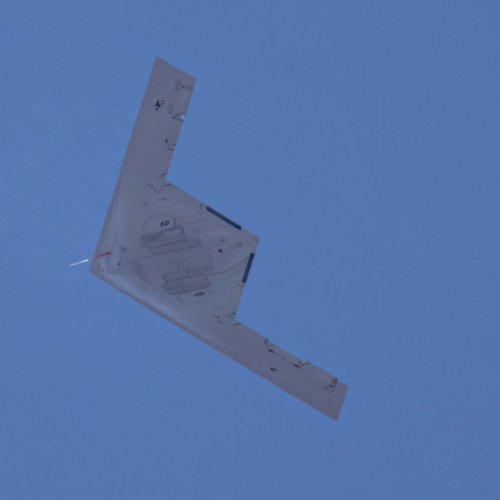
It's a trailing cone. Standard for flight tests. It also has a Pitot tube as well as SS+AoA vanes on the forward-facing boom to probe the air in a rather undisturbed part of the flow. These devices are there to provide data for the calibration of the air data system (anemometry)is it really a sensor/ towed decoy or some sort of UAP")
Forest Green
ACCESS: USAP
- Joined
- 11 June 2019
- Messages
- 12,866
- Reaction score
- 27,739
AMC Head Looks to Pair B-21 With ‘Capable, Modern Tanker’

AMC Head Looks to Pair B-21 With 'Capable, Modern Tanker' | Air & Space Forces Magazine
The Air Force is still trying to set its strategy for a future refueling capability to follow the KC-46 Pegasus.
 www.airandspaceforces.com
Forest Green
ACCESS: USAP
- Joined
- 11 June 2019
- Messages
- 12,866
- Reaction score
- 27,739
Northrop to invest $2.5B to hasten B-21 production

Northrop to invest $2.5B to hasten B-21 production - Breaking Defense
The company plans to spend $200 million in 2026 to accelerate B-21 production, Northrop CEO Kathy Warden said.
Dreamflyer
'Senior Something'
- Joined
- 13 July 2008
- Messages
- 555
- Reaction score
- 912
Northrop Discloses Sale Of Company-Owned B-21 Test Asset To U.S. Air Force | Aviation Week Network
Northrop Grumman says a previously undisclosed company-owned test aircraft has been sold to the USAF as part of a B-21 Raider production acceleration pact.
 aviationweek.com
"Northrop Grumman says a previously undisclosed company-owned test aircraft has been sold to the U.S. Air Force as part of a production acceleration agreement for the B-21 Raider."
...
" It will not change the total number of B-21s that are part of the low-rate production phase of the program, Greene noted on the company’s first-quarter earnings call."
...
- Joined
- 19 February 2007
- Messages
- 1,603
- Reaction score
- 3,294
I would speculate (groundlessly) that it could be one of the three testbed CRJ-700s or the B-737 owned by the company and used for subsystem (such as radar) testing and integration. The B-2 program used an Air Force supplied NC-135A for that purpose.
Dreamflyer
'Senior Something'
- Joined
- 13 July 2008
- Messages
- 555
- Reaction score
- 912
I would speculate (groundlessly) that it could be one of the three testbed CRJ-700s or the B-737 owned by the company and used for subsystem (such as radar) testing and integration. The B-2 program used an Air Force supplied NC-135A for that purpose.
Could be.
Though the AW-article also states: "An Air Force spokesperson confirmed the B-21 purchase."
- Joined
- 27 December 2005
- Messages
- 18,733
- Reaction score
- 33,191
A ground test B-21 airframe repurposed as a flying article?
“To support the acceleration of aircraft deliveries, we agreed to sell an aircraft to the Air Force that was previously planned to be utilized as a company-owned test asset,” CFO John Greene said April 21.
This sounds like they built another B-21 airframe for Northrop testing and have sold it the Air Force to accelerate delivery.
Attachments
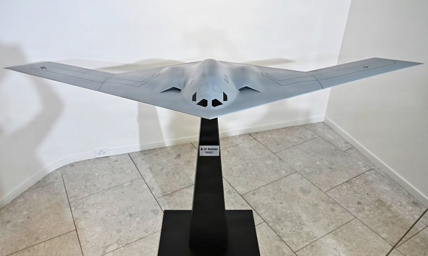

Raider, Meet Raider: AFA Unveils B-21 Model at Headquarters - Air & Space Forces Association
The Air & Space Forces Association (AFA) unveiled a replica of the Northrop Grumman B‑21 Raider stealth bomber at its...

CSAF Wilsbach makes Doolittle Raiders toast
Air and Space Forces Association President Burt Field, left, Air Force Chief of Staff Gen. Ken Wilsbach and Northrup Grumman CEO Kathy Warden pose behind a model of the B-21 Raider bomber at the AAFA headquarters in Arlington, Va., April 17, 2026. (U.S. Air Force photo by Eric Dietrich)
Attachments


Last edited:
Scott Kenny
ACCESS: USAP
- Joined
- 15 May 2023
- Messages
- 17,115
- Reaction score
- 24,283
Of course, the real joke would be if someone tried to pack a bunch of B-21s onto a Ford-class for a repeat of the Doolittle op.
Of course, the real joke would be if someone tried to pack a bunch of B-21s onto a Ford-class for a repeat of the Doolittle op.
What would be interesting is if the USAF and USN did a repeat of the early 1960s experiment where they had a C-130 Hercules land and take off successfully several times from a CV to see if it was feasible (It was) and do it with a B-21A.
what_is_that
ACCESS: Confidential
- Joined
- 9 August 2023
- Messages
- 71
- Reaction score
- 154
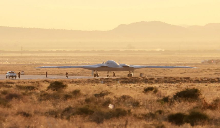
It’s really weird… At first flight of the exact same aircraft, the exhaust region was either black or a very dark color.
Maybe there's a combination of heat-tolerant RAM, very efficient bypass mixing to get the plume as cool as possible, and airflow control over the surface to keep the exhaust gases separated and stood-off (even by a pretty minor distance) sufficient to keep surface temps reasonable. Definitely easiest to do on a platform that doesn't operate at high AoAs. Could bleed a little bit of bypass into a French drain type outlet combined with careful surface shaping.
Similar principle to the porous boundary cooling in turbine blades.
They may be using the bypass air from the fan as a sheet of cooler air between the main nozzle and the upper surface and the hot core flow to help keep the upper surface somewhat cool, as opposed to completely "wrapping" the bypass air around the core flow. Also, it looks like the rear nozzles may actually be slightly higher than the rear deck of the wing, as far forward as they are, raising them up a bit from the rear surface. I also noticed the upper surface of the nozzle on the B-21 is a pointed facet, as opposed to the V-cut on the B-2 to maybe also help mixing the core and bypass flows to cool it faster? Those are just some guesses as to what they may be doing at the exhaust.
I don't think there are any "main nozzles" on the upper surface. It seems likely that the dark areas on the trailing edge are the nozzles, possibly a fixed SERN type. This may be one of the innovations that will be used in the F-47 and F/A-XX also, though likely incorporating fluidic TVC there.
I’m afraid this hypothesis has already been disproven:I don't think there are any "main nozzles" on the upper surface. It seems likely that the dark areas on the trailing edge are the nozzles, possibly a fixed SERN type.

dark sidius
ACCESS: Top Secret
- Joined
- 1 August 2008
- Messages
- 1,550
- Reaction score
- 1,615
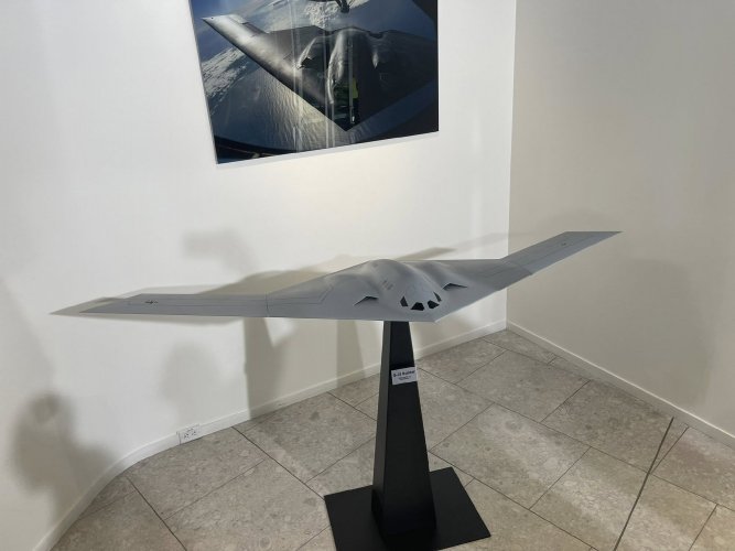
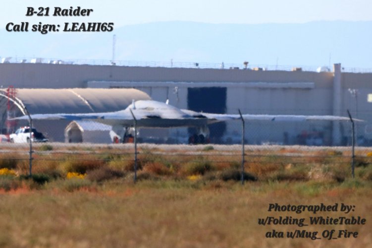
There is something strange why they mask the Exhaust on the Bottom picture if we see them on your picture ?I’m afraid this hypothesis has already been disproven:
View attachment 810091

My guess would be there is something on the surface of the expansion ramp that they want to keep as secret… Or it might just be bureaucracy…There is something strange why they mask the Exhaust on the Bottom picture if we see them on your picture ?View attachment 810114
dark sidius
ACCESS: Top Secret
- Joined
- 1 August 2008
- Messages
- 1,550
- Reaction score
- 1,615
They blurry the Square on the Tail fuselage too.My guess would be there is something on the surface of the expansion ramp that they want to keep as secret… Or it might just be bureaucracy…

dark sidius
ACCESS: Top Secret
- Joined
- 1 August 2008
- Messages
- 1,550
- Reaction score
- 1,615
Or this picture could be modified.....Are we sure this is the real exhaust ?I’m afraid this hypothesis has already been disproven:
View attachment 810091
FighterJock
ACCESS: Above Top Secret
- Joined
- 29 October 2007
- Messages
- 6,721
- Reaction score
- 7,959
Best to wait until Northrop releases the real exaust image I think.
Well this is not an official image, but an image taken by an outsider… So I believe there is no motive in modifying the image to show a fake exhaust setup.Or this picture could be modified.....Are we sure this is the real exhaust ?
On that note I think a picture of the real aircraft taken by an outsider is more reliable than any official image… Official images can be modified with all kinds of purposes.Best to wait until Northrop releases the real exaust image I think.
FighterJock
ACCESS: Above Top Secret
- Joined
- 29 October 2007
- Messages
- 6,721
- Reaction score
- 7,959
I can see your point JoshuaH.
Above was the original post containing this image. The same setup can also be seen in other pictures taken by other people:
Attachments
Last edited by a moderator:
TerraFirma
ACCESS: Restricted
- Joined
- 18 April 2026
- Messages
- 9
- Reaction score
- 17
- Joined
- 27 December 2005
- Messages
- 18,733
- Reaction score
- 33,191
That was developed for the B-2 it seems? Doesn't preclude it being on the B-21 though.
TerraFirma
ACCESS: Restricted
- Joined
- 18 April 2026
- Messages
- 9
- Reaction score
- 17
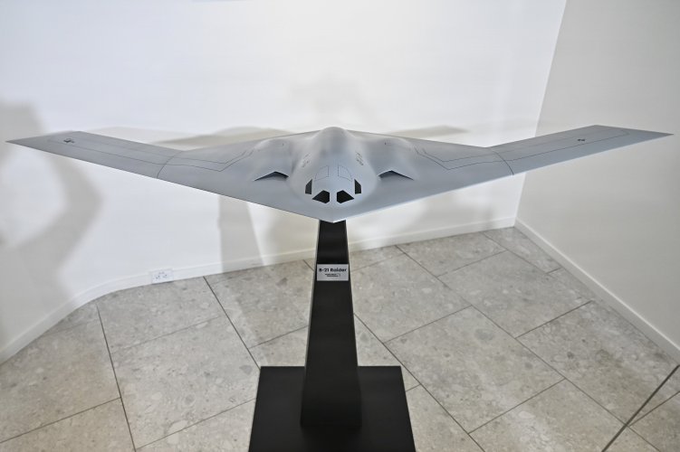
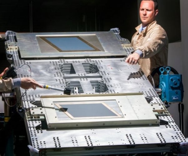
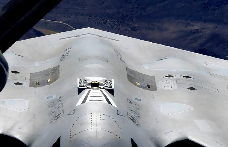
Also... What might be the purpose of the row of panels in front of the forward spar...? Since it probably does not have any leading edge control devices, what could be occupying that space...?
I deeply suspect that the answer is buried inside these pages.
Attachments
Last edited by a moderator:
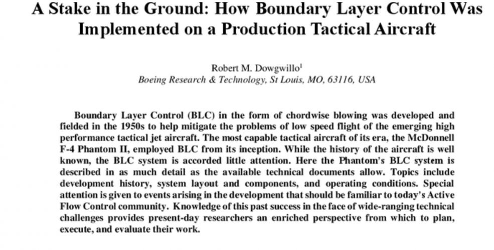
Too bad the paper is missing out on the Boundary Layer Control (BLC) system found on the Blackburn Buccaneer and MDD F-4 phantom II.
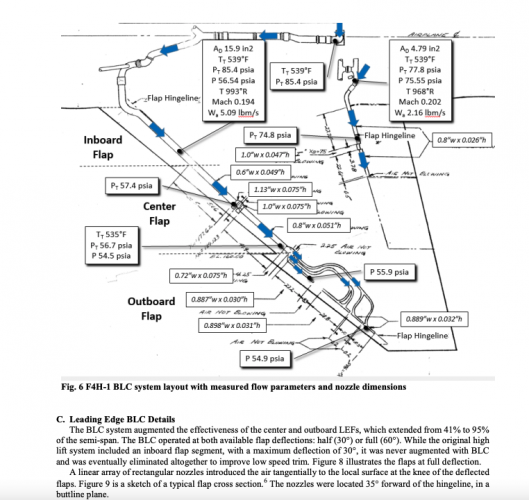
Progress of active flow control aircraft adopting rudderless flight control and STOL - Advances in Aerodynamics
Active flow control aircraft (AFCA) represent a significant development direction in next-generation aircraft design. Among them, rudderless flight control (RFC) and short takeoff and landing (STOL) are gaining widespread attentions and are gradually applied as disruptive technologies of...link.springer.com
Attachments
Last edited by a moderator:
TerraFirma
ACCESS: Restricted
- Joined
- 18 April 2026
- Messages
- 9
- Reaction score
- 17
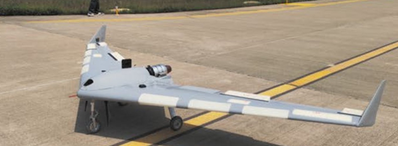
If the active flow system is as all-encompassing as I suspect it to be, then it makes perfect sense from an IR and RCS footprint angle. Take the X-47B for example and the reason why they had to do a 'last-minute fix' for the exhaust: The spillage simply heated the rear wing areas to unacceptable levels. By shrouding the jet efflux they solved a half-dozen problems in one stunningly hi-tech solution.
Attachments
TerraFirma
ACCESS: Restricted
- Joined
- 18 April 2026
- Messages
- 9
- Reaction score
- 17
B-21 don't have, doesn't need any of these.
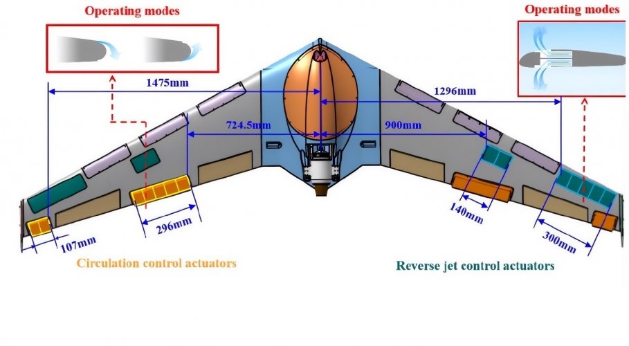
I truly have to say, with great respect and deference to your years of research, that in my opinion, I think that on this topic that you are mistaken. There are very obvious active flow regions to both upper and lower wing - and the entire upper and lower are heavily instrumented (see the rear tail of the B-21 behind the tanker) for just this reason.
Attachments
- Joined
- 1 April 2006
- Messages
- 12,034
- Reaction score
- 13,995
I've alrerady said to you at other place Smyhters that this is either [most likely] control surfaces position marks, or strain gauges. I don't see any 'active flow regions' anywhere on B-21 skin.I truly have to say, with great respect and deference to your years of research, that in my opinion, I think that on this topic that you are mistaken. There are very obvious active flow regions to both upper and lower wing - and the entire upper and lower are heavily instrumented (see the rear tail of the B-21 behind the tanker) for just this reason.
Here are a couple of reasons why I think this might not be the case:
I deeply suspect that the answer is buried inside these pages.
The X-65 demonstrator for high speed active flow control has not flown yet, which means integrating AFC would be a huge risk for the B-21 program. (Of course there is still the possibility that the technology has already been demonstrated in the black world though)
The AFC devices mentioned in the paper for trailing edge control are mostly circulation control devices, they would have to be on the very trailing edge in order to work. In contrast, the trailing edge panels on the B-21 do not extend to the end of the trailing edge.
The RCS benefits for active flow control might not be as obvious as it seems. Despite eliminating moving control surfaces (which the B-21 actually did not), AFC devices created gaps and slots on the otherwise continuous skin, which also has its own detrimental effects on RCS.
The panels in front of the forward spar being reverse jet actuators is definitely still possible, but I find it unlikely due to it creating gaps on an otherwise continuous skin surface, which would be suboptimal for stealth.
Last edited: