(also attached to this post)
In conjunction with the slight deceleration of Stage III, separation springs in the RV mechanical system pushed the RV away from the NS10 guidance set. From this point - 272 nautical miles downrange from the LF, and an altitude of 148 nautical miles - the Mk11 began its long ballistic toss through space.
...
Having only a slightly different velocity vector, Stage III and the guidance set followed the RV fairly closely throughout the long toss.
Those Minuteman IBs that were fitted with the Mk11A operated differently, having a spacer containing small rocket motors mounted atop the guidance set. Three to five seconds after electrical disconnect, a tumbler motor fired perpendicular to the Stage III centerline, imparting a rotation rate to the Stage III/NS10 assembly.
Following another programmed time interval, a retro motor was fired. This sequence generated an almost unpredictable change in the flight path and thus randomized the position of Stage III relative to the Mk11A, reducing the problem of the third stage serving as a radar beacon for the target's defenses.
The source for that is
Reentry Vehicle Development Leading to the Minuteman Avco Mark 5 and 1 – David K. Stumpf in the Fall 2017 Airpower History:
Winter 2017 – Volume 64, Number 4 Dirty Little Secret in the Land of a Million Elephants: Barrel Roll and the Lost War – William P. Head Building Air Force Intellectual Capacity: An Innovative Look […]

afhistory.org
(also attached to this post)
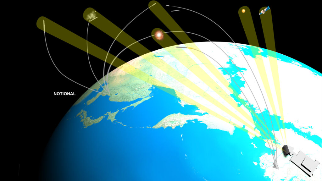
The Mark 11 series reentry vehicle had an operational requirement for a reduced radar cross section during the exoatmospheric portion of its trajectory
...
While the Mark 4 and 5 tumbled at first during reentry and thus provided a large radar return, the Mark 11 was spin stabilized so as to present a reduced radar return for as long as possible.
The Mark 11 deployed from the third stage with only a slight increase in velocity so the third stage served almost like a radar beacon for Soviet ABM systems.
...
For the Mark 11A and 11B, Avco developed a retro rocket spacer that had ten small thrusters which fired in pairs to provide a random velocity to the third stage. Before firing the retro rocket thrusters, a tumbler motor fired perpendicular to the centerline of the third stage to impart a rotation rate.
This combination randomized the third stage position relative to the reentry vehicle and thus reduced the problem of the third stage serving as a radar beacon.
RCS values for different RVs was, per SECRET/RD RAND R-1754-PR The U.S. ICBM Force: Current Issues and Future Options (October 1975):
Titan II Mk 6 Mod 3: 1.1 to 2.9m2 at 4300 to 153 MHz and 0-40° aspect.
MM2 Mk 11C: 0.0015 to 0.6m2 at 4300 to 153 MHz and 0-40° aspect.
MM3 Mk 12 Mod 3: 0.005 to 0.8m2 at 4300 to 153 MHz and 0-30° aspect.
Per various figures
Background The PARCS radar (AN/FPQ-16), located at Cavalier Air Force Station in Northern North Dakota (48.7˚ N, 97.9˚ W), was built as part of the Safeguard ballistic missile defense system, in wh…

mostlymissiledefense.com
AN/FPQ-16 PARCS (aka Safeguard PAR) is:
420-450 MHz (UHF)
14.3 MW Peak, 715 kW average powers
140 degree azimuth detection volume
24 cm (Basketball-sized) targets @ 2000 miles [3200 km] detection
Assuming the target is a sphere, a 12 cm (0.12m) radius sphere would have a rough RCS of 0.045m2.
Furthermore, a Minuteman III Post Boost Vehicle (PBV) is about 4.3 ft (1.31m) in diameter and about 1.1 ft high for the guidance section and 1.4 ft high for the propulsion section (2.5 ft / 0.762 m).
Simple RCS estimates for the PBV:
Head on PBV (0.7 x 0.7m Flat Plate @ 425 MHz): 6.07 m2
Side on PBV (Cylinder @ 425 MHz): 0.62m2
Extrapolating with the Radar Equation we get Safeguard PAR vs:
MM3 Post-Boost Vehicle (Head): 10900 km [6772 mi]
MM3 Post-Boost Vehicle (Side): 6100~ km [3790 mi]
Titan 2 Mk 6 (Head): 7100 km [4411 mi]
Titan 2 Mk 6 (Side): 9000 km [5592 mi]
Minuteman II Mk 11C (Head): 1300 km [807 mi]
Minuteman II Mk 11C (Side): 6100 km [3790 mi]
Minuteman III Mk 12 (Head): 1850 km [1149 mi]
Minuteman III Mk 12 (Side): 6570 km [4082 mi]
Some things that shake out from this thought experiment:
It clearly shows how ABM is a multiplicative effort -- if all you have is a single radar (PAR A) in South Dakota; low RCS MIRVs aimed directly at it won't be detected until 800~ miles out.
But if you have a second radar (PAR B) 500-700 miles away; that PAR gets the side view of the low-RCS MIRVs headed to PAR A; and can get 3000+ mile ranges on them, and in turn tell PAR A about this.
Furthermore, this shows how virtual attrition of an ABM system impacts enemy MIRV patterning.
MIRV systems have very low energies -- Minuteman III's was, per RAND R-1754-PR:
Shroud = 200 lb
3 x RVs = 1050 lbs
Chaff = 210 lbs
Bus Propellant: 257 lb
Bus Dry Mass: 348 lb
Total Bus Mass: 2065 lb
Post Boost Vehicle ΔV = 1250 ft/sec (381 m/s)
Post Boost ISP = 282 seconds
Post Boost Vehicle Burn Time = 440 sec (230 at max thrust)
Post Boost Vehicle Thrust (Axial): 316 lbf
Post Boost Vehicle Thrust (Pitch): 22.6 lbf
Post Boost Vehicle Thrust (Yaw): 22.6 lbf
Post Boost Vehicle Thrust (Roll): 18.6 lbf
Max MIRV footprint = 300 x 900 n.mi
Please note that this is for a hypergolic liquid fuelled PBV. Polaris/Poseidon/Trident SLBMs use solid propellant gas generators (SPGG); because the USN is deathly afraid of putting hypergols to sea; and as a result, they've got much lower ISPs.
Rubber banding the MM3 PBV down to 182-200 ISP (a reasonable guess for a SPGG system), USN Post Boost Vehicles are around 800-890 ft/sec (243.8 - 271.2 m/s) ΔV.
This has implications, particularly if the system requires post-release back-off manuvers following each MIRV release to keep accuracy high.
[If you don't do 'back off' manuvers, odds are high that you hit the released MIRVs (or other objects) with rocket exhaust from the PBV.]
In the absence of any ABM system:
1.) You can dispense with chaff to increase your delta-V and footprint size.
I strongly suspect chaff was gotten rid of anyway, because there's not enough time + delta V to achieve a significant separation distance from the MIRVs and avoid the enemy from using the chaff clouds as a radar target to volume search in a conical cylindrical pattern around the chaff to find the MIRVs.
Think about it -- you've made a 'modern' low-RCS MIRV (0.0015 m2 @ 0 deg) and now you're going to surround it with radar beacons? Stealth aircraft don't dump chaff everywhere to camouflage themselves...
2.) You can keep the MIRVs on the bus as long as possible to increase accuracy via star trackers + on board INS + gravity sensors.
3.) 100% of the Bus' Delta-V is available for footprinting, course correction, and 'back-off' manuvers.
If an ABM system exists...
1.) You now have to reserve a significant amount of Delta-V for disposal of the warhead bus; as it presents a significant radar target from which an enemy could use as the basis for a volume search based off estimated post-boost performance characteristics of the post-boost vehicle -- i.e. given 'x' amount of ΔV, what radius do we have to search to find the MIRVs?
2.) Target object debussing and deployment must occur before the target complex comes over the radar horizon for enemy ABM systems; because the enemy can use a radar (or other sensors) to track the post-boost vehicle -- heavy warheads and light decoys will have different post-boost vehicle precession (wobble) rates.
A.) MIRVs must now be released as soon as possible, and thus lose the advantage of mid-course corrections from the bus.
B.) The PBV has to thrust longer to impart the higher separation velocities to each target object (MIRV/Chaff Bundle/Decoy) so that the target complex positioning is locked in before it comes within range of ABM systems -- i.e. all the MIRVs and decoys are positioned so that no one interceptor can kill multiples.
All this means MIRV bus footprints will be much smaller in an area covered by ABM; less targets will be able to be covered, in turn needing more missiles to achieve the same target coverage (on top of shootdown losses, etc).
PS -- circling back to how ABM is a multiplicative effort -- if you have a line of ABM radars, you can get views of enemy objects' wake turbulence on the offset radars with side views:
Thirty years ago, we pointed the following radars in the Kiernan Re-Entry Measurement System (KREMS) complex at Kwajalein:
Altair (VHF-UHF)
Tradex (L to S)
Alcor (C)
MMW (Ka)
at the following targets:
25 May 1990: Learjet 36
15 June 1990: C-5A Galaxy
And got some very intersting data regarding tracking wakes (look at that PDF).
Now, given that a C-5 cruises at around 540 MPH (792 ft/sec)...what does this mean for enemy objects entering the atmosphere at 24,000+ ft/sec, some thirty times faster than said aircraft?
If you want moderately light 'heavy' decoys, the "cheapest" way of doing it is to stack them on top of small MIRVs dixie-cup style.
We tested the so-called Small Rigid Lightweight Replicas (SRLR) with RCT-1 (Radar Credible Target 1 back on Minuteman III Operational Test (OT) Mission GT-170GM which was way back in 1999 to test the GBR-P prototype.
For that mission, one of the three MIRV locations was set aside and was loaded with:
1 x SRV - Small Re-Entry Vehicle
2 x SRLR - Small Rigid Lightweight Replicas
The SRLRs were stacked on top of the SRV and were X-Band Signature matched to the SRV.
It flew a normal Minuteman III Operational Test trajectory with the following time hacks:
410 seconds after launch, the bus deploys the RCT-1 stack and backs away.
At 1050 seconds, the first SRLR is deployed from the RCT-1 stack at 1.7 m/s separation velocity
At 1200 seconds, the chaff package is deployed at 4 m/s sep velocity
At 1250 seconds, the second SRLR is released at 1.7 m/sec velocity
By 1450 seconds, there is now 340 meters separation between the targets.
At 1550 seconds, chaff release begins; using a standard aircraft chaff package (RR-170/AL) dispersing 3 million chaff pieces cut to L, C and X band lengths.
At 1700 seconds the SRV target impacts the target area.
With some crude guessing -- if everything has to be at 300+ meters separation by 300 seconds before impact, that puts it at about 1800 km [1100~ miles] from the target zone.
But the big issue is that the SRLRs are an open cone; meaning they're going to have a radar wake totally different than an actual RV with a closed cone....
Some more information on the RCT-1 stack:
Sandia target array helps test BMDO’s experimentalnational missile defense radar
www.sandia.gov
Sandia target array helps test BMDO’s experimental national missile defense radar
BY JOHN GERMAN
FRIDAY, FEBRUARY 9, 2001
Labs engineers, together with the US Army Space and Missile Defense Command, helped the Ballistic Missile Defense Organization (BMDO) test the limits of a national missile defense radar in September by dispersing into space an array of small objects that to the radar looked something like reentry vehicles (RVs) and deployment debris heading toward Earth.“Our role was to throw out a lot of interesting stuff for the radar to look at,” says Sandia mission project manager Dan Talbert of Targets Dept.15415.The Sept. 28 flight was the second in a series of RCT (Radar-Credible Targets) tests meant to examine the capabilities of the BMDO’s most advanced X-band radar, called the Ground-Based Radar Prototype (GBR-P). The GBR-P watched Sandia’s carefully orchestrated show from Kwajalein Atoll in the Pacific.
Making a scene
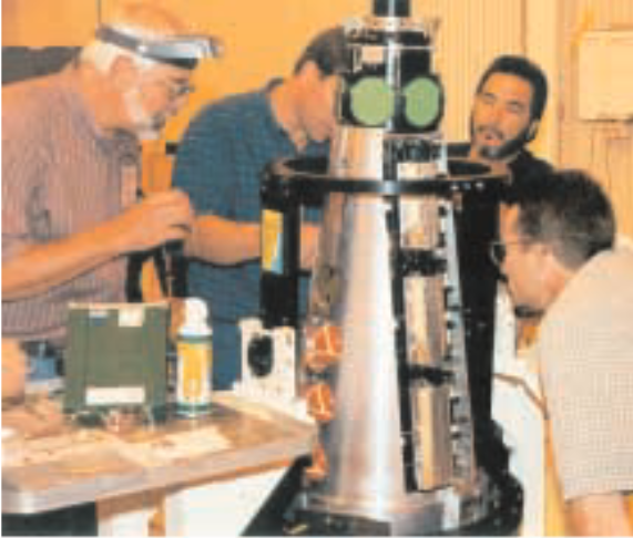
A Minuteman III missile launched from Vandenberg Air Force Base carried an RV-like plat-form, called a target deployment structure (TDS),that was specially created by Sandia to disperse a grouping of targets into the night sky. During the flight, six hockey-puck-shaped objects and six croquet-ball-like objects ejected from the TDS, along with six beach ball-sized balloons and one small rigid lightweight replica —essentially a five-foot-high cone that served as an RV surrogate for the mission. Many of the 20 objects mimicked the way areal RV might appear to the radar. The BMDO then used the GBR-P to assess the credibility of each target.“The RCT-2 target complex provided objects and spatial separations not heretofore available on [national missile defense] flight tests and hence an opportunity for testing GBR-P’s acquisition,wide-band tracking, and discrimination functions on a stressing target scene,”according to a BMDO test summary.“From a radar standpoint it was a totally successful mission,” says Dan.“Our customer was delighted.”
RCT-2 tests Sandia
To create the target scene the BMDO wanted, Labs propulsion experts built from scratch and tested a new type of solid-fuel thrust motor that spun the RV up to one rotation per second and then “de spun” it back to near zero, says Dan. “We went from pencil and paper to delivering a flight-certified spin system in eight months,” he says. “It was a small miracle we were able to develop and build the system on time and that it worked so well.”In fact, he says, everything Sandia put on the RV was developed specifically for the test except the rigid light replica. The pucks and balls had never been used before, and their ejection systems were newly designed and tested on the ground.
The balloon ejectors were also a new design for the RCT-2 mission. Sandia’s machine shops created the five-foot-tall TDS out of a solid chunk of aluminum that needed a lot of internal and external precision machining, Dan says. “We were able to go from the drawings straight to the shops,” he says. “We would not have been able to deliver without an in-house precision machining capability.”Core team members included lead technician Jimmy Aldaz (15413), lead mechanical engineer Robert Brown (15414), project engineer David Foral (15415), lead electrical engineer Martin Imbert (2663), lead mechanical designer Mel Krein (15415), mechanical designer Jacky Martinez (15415), electrical systems engineer C.R.N idever (ret.), mechanical technicians Brian Pardo (15413) and John Stanalonis (15417), electrical technician Doug Pastor (2663), and Dan.About 25 other people from Centers 2500,2600, 9100, 14100, and 15400 contributed.
PREPARING AN RV-like platform called a target deployment structure (TDS) prior to the RCT-2 test were (left to right) Mel Krein (15415), Brian Pardo,Jim Aldaz (both 15413), and Rob Brown (15414). Target objects that look like pucks (top of TDS), balls (left side of TDS), and cannisterized balloons (right side of TDS) are visible.