Intake design and general stealth discussions

There are important aspects you forget, if you are in a shadow still there is light, the concept of creeping wave is also related to power density, you are comparing an antena to the sun, the sun can fill the whole horizon, basically, no mountains will stop it can not compare, you are giving me an antena with very limited radiation power, remember light is also absorbed by the atmosphere, radar too, it weakens plus the human body is not homogeneous, is not perfectly smooth, there is plenty of diffraction around it, there are creeping waves in human body, creeping waves exist simply because the Huygens principle.


View attachment 620547

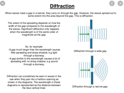
in Fig 4 you have a description of concentric circles for long waves and a narrow ray for microwave, however both have the same nature,


DSI intake can deal with creeping waves to an extent like i said to you because at 100 km the atmosphere has absorbed enough power density that it is very weak
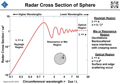
Firstly, there are light behind a mountain because light hitting others object, terrains behind the mountain will scattered back in a wide cone, so some of that will hit the mountain. If you go to the true shadow region, aka the side of the hemisphere not facing the sun, there is no light from the sun. This is particularly evident when planet near the sun have half of their hemisphere at 400-500 degree Celsius and the other half at -150 degree Celsius. If light/ radio wave can always fully curve a whole circle around the object regardless of their size then we would never have radar horizon limit, there will be no night time, and you will always see object around corner. As none of those are possible, we know that the diffraction angle/creeping potency is depending on the wavelength size and the object size. If the wave is too small compare to the object, the diffraction angle is narrow. If the wavelength approach the size of the object, then it start to curve around. There is very good reason, they divide RCS into 3 regions: Optical/Mie/Rayleigh and very low frequency radar are considered better against stealth aircraft.


The caret intake you still do not want to admit, is for higher speeds, so it can keep pressure recovery of 95% at Mach 2, DSI can not do that does not matter how much you want to argue about its smoothness, in aerodynamic terms it will not help you compared to caret variable geometry intakes.
I have never say caret inlet isn't for high speed so please don't strawman my argument.


The bump and sharp edges are diffraction sources, you still think the bump by being smooth is invisible to radar, it is not. in fact you have a contradiction F-22 has chines good for eliminating creeping wave, F-15 has round cross section no good for creeping wave, but you say the bump is good
The angular edge redirect creeping wave so that it less likely to come back to the source. The smooth curve eliminate surface wave scattering. Please distinguish between the surface wave scattering and the creeping wave return.
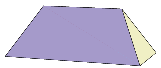
To mitigate both surface wave scattering and creeping wave return, you want a design that isn't circular or tube like but also doesn't have many sharp edges and discontinuities. Sort of an angular shape with blunt edge. That why F-22, F-35, B-2 doesn't have tube body like B-52, F-16 but they also doesn't have a full facet body like F-117. To further reduce the effect of edge diffraction, their wing leading and trailing edges are treated with RAM.
 
There are important aspects you forget, if you are in a shadow still there is light, the concept of creeping wave is also related to power density, you are comparing an antena to the sun, the sun can fill the whole horizon, basically, no mountains will stop it can not compare, you are giving me an antena with very limited radiation power, remember light is also absorbed by the atmosphere, radar too, it weakens plus the human body is not homogeneous, is not perfectly smooth, there is plenty of diffraction around it, there are creeping waves in human body, creeping waves exist simply because the Huygens principle.


View attachment 620547

in Fig 4 you have a description of concentric circles for long waves and a narrow ray for microwave, however both have the same nature,


DSI intake can deal with creeping waves to an extent like i said to you because at 100 km the atmosphere has absorbed enough power density that it is very weak
Firstly, there are light behind a mountain because light hitting others object, terrains behind the mountain will scattered back in a wide cone, so some of that will hit the mountain. If you go to the true shadow region, aka the side of the hemisphere not facing the sun, there is no light from the sun. This is particularly evident when planet near the sun have half of their hemisphere at 400-500 degree Celsius and the other half at -150 degree Celsius. If light/ radio wave can always fully curve a whole circle around the object regardless of their size then we would never have radar horizon limit, there will be no night time, and you will always see object around corner. As none of those are possible, we know that the diffraction angle/creeping potency is depending on the wavelength size and the object size. If the wave is too small compare to the object, the diffraction angle is narrow. If the wavelength approach the size of the object, then it start to curve around. There is very good reason, they divide RCS into 3 regions: Optical/Mie/Rayleigh and very low frequency radar are considered better against stealth aircraft.


I have never say caret inlet isn't for high speed so please don't strawman my argument.


The angular edge redirect creeping wave so that it less likely to come back to the source. The smooth curve eliminate surface wave scattering. Please distinguish between the surface wave scattering and the creeping wave return.
To mitigate both surface wave scattering and creeping wave return, you want a design that isn't circular or tube like but also doesn't have many sharp edges and discontinuities. Sort of an angular shape with blunt edge. That why F-22, F-35, B-2 doesn't have tube body like B-52, F-16 but they also doesn't have a full facet body like F-117. To further reduce the effect of edge diffraction, their wing leading and trailing edges are treated with RAM.
Ronny

DSI intakes as you already say it can not compete with a variable geometry intake for speeds beyond 0 km to Mach 2, in fact your average DSI has its best pressure recovery at Mach 1.7, a regular F-14 has an intake with its best pressure recovery at Mach 2.1, so definitively if you have a more complex one like SR-71 the pressure recovery can go to Mach 2.5 easily.
So there is no comparison regardless you say it is more stealth or not, a variable geometry caret will give you better performance but at higher price both in maintenance and stealth.


Now remember this
1571954740583.png
1571957144564.png

when an object is far away from a light source light rays are parallel, when it is close they are divergent, if you place a ball at 1 meter from a lamp the shadow side of the ball has enough light to be very visible, you can stay in the shadow side and it is pretty visible, as the light source is farther the shadow becomes darker, if you see that you will understand stealth, the amount of creeping wave is higher when the light source is closer, but when it is farther, less and less light enters the shadow, stealth is that so chines or trapezoidal shapes reduce radar waves creeping effect, but because it is darker and farther in few words the radar is farther away.

Now if you remember a leopard in Africa can hunt at night, why? remember for us our eyes are not so sensitive, but for a leopard his eyes allow it to hunt at night, in a very dark night that for us will not let us see, so even on earth it is not absolute darkness, so radars need to become as the eyes of a leopard more sensitive to lower power density and more powerful as emitters, but stealth does not mean not visible, it means less visible as the distance grows and such technologies just makes it harder as the distance grows.

remember the eyes of a leopard concentrate light so the beams become convergent, a parabola does the same thing that a retina does to our eyes


1571963061395.png

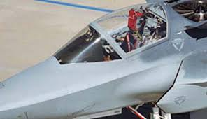
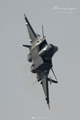
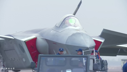
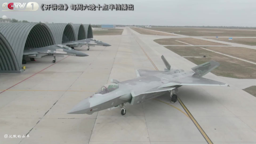
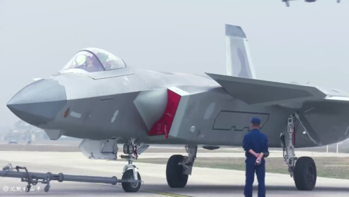
The DSI makes J-20 a hybrid of F-15 and F-22 to some extent since the flat chines of F-22 are better to deal with creeping waves, both caret and DSI have aerodynamic compromises the caret has a boundary layer diverter but DSI a bump that reminds us of the round cross section of F-15
 
Last edited:
Just remember stealth is not radar invisibility,

Yes, stealth is not invisibility. It is reducing detection range and probability to increase aircraft survivability. Instead of being able to engage you 10 miles away, they can't until you are right on top of them. That is the point.

is lower signature treatment, and improvements in radar technology render stealth useless, diffraction and power density output of radars make stealth useless

Stealth aircraft are already designed to account for diffraction. They have been for a long time, even before there were computational tools.
Modern stealth aircraft have been around for nearly 40 years, yet they are not yet "useless" in the face of improvements in radar technology, wether those improvements are increased power density, better signal processing and software, or bistatic radars.
 
But we have a few problems here. First, if the compression is being done by a normal shockwave, I don't think there's any possible capture here.

You still have the air moving at much higher speed through the same area upstream of a normal shock than downstream, leading to a substantial increase in density downstream. At a free stream Mach number of 2.0 compression is about a factor of 2.7, giving virtually sea level density at 30k feet altitude.

Which is presumably why in afterburner at high speeds, thrust can exceed the value at sea level, despite the thinner air it has to work with.
 
Ronny
DSI intakes as you already say it can not compete with a variable geometry intake for speeds beyond 0 km to Mach 2
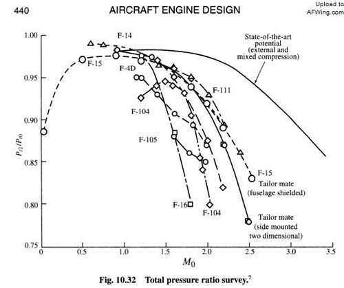
I think it depends, I think variable inlet can be optimized to wider range of speed so generally most of them are better than DSI at high Mach, but I don't think DSI is necessarily worse than all kinds of variable inlets. For example. according to this chart F-4D inlet isn't better than J-10 DSI.
TWUDq.jpg


Now remember this
View attachment 620597

when an object is far away from a light source light rays are parallel, when it is close they are divergent, if you place a ball at 1 meter from a lamp the shadow side of the ball has enough light to be very visible, you can stay in the shadow side and it is pretty visible, as the light source is farther the shadow becomes darker, if you see that you will understand stealth, the amount of creeping wave is higher when the light source is closer, but when it is farther, less and less light enters the shadow, stealth is that so chines or trapezoidal shapes reduce radar waves creeping effect, but because it is darker and farther in few words the radar is farther away.
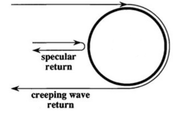
The fact that wave only curve a whole revolution around the object when they approach the size of the object has nothing to do with whether the source is powerful or not. If your wavelength is too small compare to the object, there will be no creeping wave return regardless of how powerful the source is. Case in point, in an anechoic chamber the emitter is only few meter away from the aircraft. Please don't confuse between creeping wave return and surface wave scattering. In your ball example, the shadow side of the ball could be visible due to backscatter from object behind the ball. If the wave truly creeping a whole circle around the ball, you will be able to see its shadow side from the light side.


Now if you remember a leopard in Africa can hunt at night, why? remember for us our eyes are not so sensitive, but for a leopard his eyes allow it to hunt at night, in a very dark night that for us will not let us see, so even on earth it is not absolute darkness, so radars need to become as the eyes of a leopard more sensitive to lower power density and more powerful as emitters, but stealth does not mean not visible, it means less visible as the distance grows and such technologies just makes it harder as the distance grows.

remember the eyes of a leopard concentrate light so the beams become convergent, a parabola does the same thing that a retina does to our eyes

Leopard can sometimes hunt at night because his eyes are sensitive enough to capture photons from the moon, the stars and not because sunlight curve around the earth. Secondly, no one here ever said stealth is invisible, it really pointless to argue against that.


The DSI makes J-20 a hybrid of F-15 and F-22 to some extent since the flat chines of F-22 are better to deal with creeping waves, both caret and DSI have aerodynamic compromises the caret has a boundary layer diverter but DSI a bump that reminds us of the round cross section of F-15
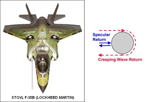
Creeping wave return are traveling wave that able to travel a whole circle around the object. As long as your object isn't a sphere or cylinder, the effect of creeping wave are already mitigated a lot. F-35 nose isn't a cylinder so it already reduce the effect of creeping wave return. The bumps here help reduce surface wave scattering. Why else do you think among all modern stealth aircraft F-22, F-35, B-2, X-47, RQ-170, MQ-25, none of them have as many sharp facets as the F-117 ?. Pretty much their only sharp edges are at trailing and leading edges but those are treated with RAM

1.PNG
 
But we have a few problems here. First, if the compression is being done by a normal shockwave, I don't think there's any possible capture here.

You still have the air moving at much higher speed through the same area upstream of a normal shock than downstream, leading to a substantial increase in density downstream. At a free stream Mach number of 2.0 compression is about a factor of 2.7, giving virtually sea level density at 30k feet altitude.

The issue is, what is compared to what?

This is basically a quantitative discussion. For instance, Mach 2.7 at 35k feet gives you roughly the same MFR as Mach .9 at sea level, assuming the inlet's pressure recovery is about the same at the different regimes. On the other hand, if you want to do Mach 1.2 at 35k feet with the same level of thrust as Mach .9 sea level, you'll need a larger inlet.

As an alternative, we could instead do a comparison between Mach .5 and Mach 2, which is a factor of 4 in terms of velocity. In this case, since air density drops by about 70% from sea level to altitude, you get a total factor of about 1.2x sea level at Mach .5.

So inlet area in fact becomes a tuning factor when it comes to engine performance, too small, bad performance at a variety of altitudes and speeds, too big, bad performance at low speeds.

====

This originally came up in discussing as to whether the J-20's different inlet could allow the J-20 to supercruise on Al-31. The answer was ultimately no, even with the best case inlet area calculations (which could very well be wrong), except that it could hit a pseudo-supercruise (dive or AB into supersonic) at 35k ft of Mach 1.2-1.4 if the best case inlet area calculations were used. So that's an important flight regime, i.e, MFR at Mach .9 and when breaking the Mach barrier, so that's a flight regime we should be concerned about.

===

And TBH Trident, I was more concerned about puncturing your claims regarding speed being able to unconditionally overcome air density issues at altitude. If you look at real thrust / altitude diagrams for engines, as with the one you showed me, it's hard to pinpoint MFR as the only factor limiting engine performance at altitude. Likely, there's also factors of total pressure recovery at different altitudes and speeds that limit the airframe. I'll point out that with your Al-31 chart, at quite a few altitudes the Al-31 thrust just flatlines despite increasing Mach. Another possible factor is that the charts we've seen discuss pressure recovery as a function of speed. But does pressure recovery also vary as a factor of freestream air density? That could be an interesting factor, but quite likely dynamic pressure overwhelms static pressure when it comes to inlet TPR, even if dynamic pressure is supposed to be near-constant if the inlet does it work correctly at the compressor.

===

I will also note that I'm very happy that we're having a serious conversation about inlets. This is, as overscan's book discussed, an oft-overlooked element of fighter design. Stuff like wing designs, wing loading, engine designs, and so on, these are all way sexier for enthusiasts than the inlet. I didn't quite manage to catch your insulting statement, so I'd like to point out I enjoy our conversation.
 
Last edited:
I think it depends, I think variable inlet can be optimized to wider range of speed so generally most of them are better than DSI at high Mach, but I don't think DSI is necessarily worse than all kinds of variable inlets. For example. according to this chart F-4D inlet isn't better than J-10 DSI.
View attachment 620603


Leopard can sometimes hunt at night because his eyes are sensitive enough to capture photons from the moon, the stars and not because sunlight curve around the earth. Secondly, no one here ever said stealth is invisible, it really pointless to argue against that.


[
Creeping wave return are traveling wave that able to travel a whole circle around the object. As long as your object isn't a sphere or cylinder, the effect of creeping wave are already mitigated a lot. F-35 nose isn't a cylinder so it already reduce the effect of creeping wave return. The bumps here help reduce surface wave scattering. Why else do you think among all modern stealth aircraft F-22, F-35, B-2, X-47, RQ-170, MQ-25, none of them have as many sharp facets as the F-117 ?. Pretty much their only sharp edges are at trailing and leading edges but those are treated with RAM

View attachment 620604
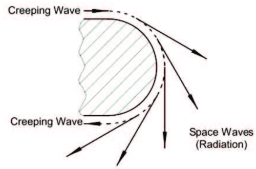
the drawing you have of the creeping wave is not accurate, in fact remember the title of the document i gave you

CREEPING-WAVE DIFFRACTION CONCEPT When a wave is incident upon an opaque object which is large compared to the wavelength, a shadow is formed. However, some radiation penetrates into the shadow region due to diffracted rays as shown


they say diffraction, in fact you have to see how they explain it
1571984992248.png
These rays are produced by incident rays which are tangent to the surface of the body. Each tangent ray splits at the point of tangency with one part continuing along the path of the incident ray and the other traveling along a geodesic on the surface of the body. At each following point, it splits again with one part traveling along the geodesic and the other reradiating along a tangent to the geodesic. rays are produced, one of which is reradiated at each point of the geodesic.


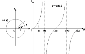
It basically due to the curvature of the leading edge, (it has tangents ) you just need to see a graph and you will see the fact a cylinder or sphere has many tangents


1571985274026.png

thus as you can see, a circle has no one, no 360 tangents, it has many thus as the title says CREEPING-WAVE DIFFRACTION CONCEPT is diffraction what causes the creeping wave


Any way you are free to believe diffraction is not the cause, the only thing i can tell you, is DSI intakes are visible, F-22 can be detected at ranges of at least 40-60km by radars on Su-35, at 120 km well it may not be detected.

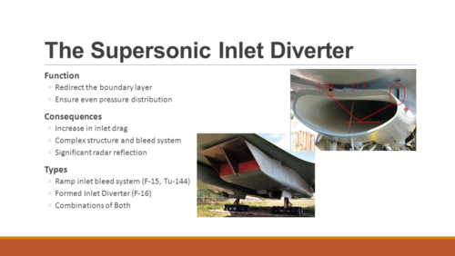
You insistence on DSI intake might have better performance is not real, as speed grows more boundary layer is ingested, thus you need bleeding mechanical systems

1571985720318.png

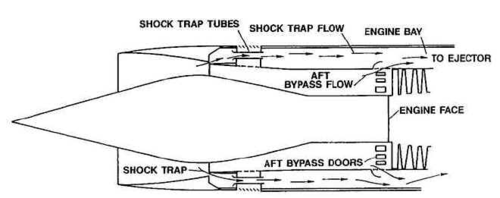
there you can see the bleeding system of an F-14, faster speeds also need bypass doors

1571985805920.png


The DSI of J-20 has no mechanical system, no bleeding system why? simple the speeds it manages, if it goes at higher speeds not only more boundary layer will ingest but it will have a mass flow of air that needs to be removed, so no, DSI intakes can not compete if you go from 0 km to more than Mach 2+ , the capture area, throat area and shock ramps are variable because of the speed and some times they need bypass flow.

1571986049201.png
the pointy cowl of X-35 is good for reflection, but not good for diffraction, stealth aircraft always send radar waves back to the radar emitter, but since power is low, well at 100 km the signal might be too weak for a radar to recognize it as a F-22, is like if we try to see details at 100 km, can you see the eye color of a person at 1 km from you? can you see if she has moles at 2000 meters? to do that you need convergent rays. or a parabola

The bump on DSI are not perfect circles they are half cones, by frontal cross section are half circles, good for diffraction but diagonally they are wedges, that are good for reflection away from the radar, on a head to head approach they reduce RCS, but not from the sides, chines and flat sidewalls are good for the sides, so they are good for reflection away from the radar

1571986992411.png

a wedge has several facets like F-117 to send energy away from the radar, by wedge i mean they have an acute shape a pointy parabola or, consider the DSI`s bump on 3 axis, X and Y axis are a semi circle but Z and Y axis are a parabola


1571987959841.png

so the parabola has an angle of reflection that sends energy away from the radar ahead of the aircraft due to this simple formula

The angle of reflection
aimg58.gif
of a ray or beam is the angle measured from the reflected ray to the surface normal. From the law of reflection,
aimg59.gif
, where
aimg56.gif
is the angle of incidence.
aimg58.gif
is measured between the ray and a line normal to the surface that intersects the surface at the same point as the ray.

http://140.177.205.24/physics/AngleofReflection.html
 
Last edited:
the drawing you have of the creeping wave is not accurate, in fact remember the title of the document i gave you
CREEPING-WAVE DIFFRACTION CONCEPT When a wave is incident upon an opaque object which is large compared to the wavelength, a shadow is formed. However, some radiation penetrates into the shadow region due to diffracted rays as shown
they say diffraction, in fact you have to see how they explain it
These rays are produced by incident rays which are tangent to the surface of the body. Each tangent ray splits at the point of tangency with one part continuing along the path of the incident ray and the other traveling along a geodesic on the surface of the body. At each following point, it splits again with one part traveling along the geodesic and the other reradiating along a tangent to the geodesic. rays are produced, one of which is reradiated at each point of the geodesic.
It basically due to the curvature of the leading edge, (it has tangents ) you just need to see a graph and you will see the fact a cylinder or sphere has many tangents
View attachment 620609
thus as you can see, a circle has no one, no 360 tangents, it has many thus as the title says CREEPING-WAVE DIFFRACTION CONCEPT is diffraction what causes the creeping wave
Any way you are free to believe diffraction is not the cause

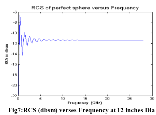
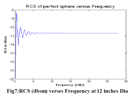
When did I ever say diffraction is not the cause for creeping wave? I only explain one thing and one thing only to you, how much wave can diffract into shadow region depend on its wavelength size compared to the object. If the wavelength is too small compared to the object, then the effect of diffraction is minimal and there is no creeping wave return. So just because creeping wave return is the result of diffraction doesn't mean all diffraction will generate creeping wave return. Why else do you think they have to divide RCS of an object into 3 separate regions to calculate: Optical/Mie/Rayleigh?. Why else do you think RCS of a sphere only fluctuated significantly when the wavelength approaches its radius?. Why else do you think the double-slit experiment is done with a slit instead of a large gap?. Why else do you think very low frequency radar is considered better against stealth aircraft?. All the question have the same answer. The amount of diffraction depending on the size of object versus the wavelength. To have creeping wave return effect, the illuminating wave must have wavelength similar to object size.
1.PNG RCS2.PNG

rcs.PNG


the only thing i can tell you, is DSI intakes are visible, F-22 can be detected at ranges of at least 40-60km by radars on Su-35
If that was possible there is no need for anti stealth radar. Any random AEW&C or SAM radar will detect stealth aircraft from 300-400 km because Su-35's radar even though strong, still pitifully weak compared to ground radar


You insistence on DSI intake might have better performance is not real, as speed grows more boundary layer is ingested, thus you need bleeding mechanical systems
there you can see the bleeding system of an F-14, faster speeds also need bypass doors
The DSI of J-20 has no mechanical system, no bleeding system why? simple the speeds it manages, if it goes at higher speeds not only more boundary layer will ingest but it will have a mass flow of air that needs to be removed, so no, DSI intakes can not compete if you go from 0 km to more than Mach 2+ , the capture area, throat area and shock ramps are variable because of the speed and some times they need bypass flow.
When did I ever say J-10 DSI is better than F-14 or SR-71 inlet at high speed?
I said it is better than F-4D based on the chart.


the pointy cowl of X-35 is good for reflection, but not good for diffraction, stealth aircraft always send radar waves back to the radar emitter, but since power is low, well at 100 km the signal might be too weak for a radar to recognize it as a F-22, is like if we try to see details at 100 km, can you see the eye color of a person at 1 km from you? can you see if she has moles at 2000 meters? to do that you need convergent rays. or a parabola
The bump on DSI are not perfect circles they are cones frontally by frontal cross section are half circles, good for diffraction but diagonally they are wedges, that are good for reflection, on a head to head approach they reduce RCS, but not from the sides, chines are good for the sides, so they are good for reflection away from the radar

a wedge has several facets like F-117 to send energy away from the radar, by wedge i mean they have an acute shape a pointy parabola or, consider 3 axis, X and Y axis are a semi circle but Z and Y axis are a parabola

so the have an angle of reflection that sends energy away from the radar ahead of the aircraft due to this simple formula
The angle of reflection
aimg58.gif
of a ray or beam is the angle measured from the reflected ray to the surface normal. From the law of reflection,
aimg59.gif
, where
aimg56.gif
is the angle of incidence.
aimg58.gif
is measured between the ray and a line normal to the surface that intersects the surface at the same point as the ray.

http://140.177.205.24/physics/AngleofReflection.html
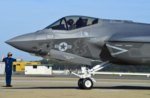
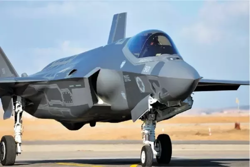
The DSI smooth cowl on F-35 has no gaps unlike a variable inlet, so DSI minimizes the amount of scattering from surface traveling wave. The curvature mean wave can curve/diffract around it easier. But the cowl is not a sphere, when the surface wave curve/diffract around it, the do not make a full circle back to the radar, they go into the inlet instead. The internal of the inlet will scatter the wave inside multiple time, with each bounce further reduce the wave strength when it hit the RAM surface
F35B STOVL.jpg
 
When did I ever say diffraction is not the cause for creeping wave? I only explain one thing and one thing only to you, how much wave can diffract into shadow region depend on its wavelength size compared to the object. If the wavelength is too small compared to the object, then the effect of diffraction is minimal and there is no creeping wave return. So just because creeping wave return is the result of diffraction doesn't mean all diffraction will generate creeping wave return. Why else do you think they have to divide RCS of an object into 3 separate regions to calculate: Optical/Mie/Rayleigh?. Why else do you think RCS of a sphere only fluctuated significantly when the wavelength approaches its radius?. Why else do you think the double-slit experiment is done with a slit instead of a large gap?. Why else do you think very low frequency radar is considered better against stealth aircraft?. All the question have the same answer. The amount of diffraction depending on the size of object versus the wavelength. To have creeping wave return effect, the illuminating wave must have wavelength similar to object size.


When did I ever say J-10 DSI is better than F-14 or SR-71 inlet at high speed?
I said it is better than F-4D based on the chart.


The DSI smooth cowl on F-35 has no gaps unlike a variable inlet, so DSI minimizes the amount of scattering from surface traveling wave. The curvature mean wave can curve/diffract around it easier. But the cowl is not a sphere, when the surface wave curve/diffract around it, the do not make a full circle back to the radar, they go into the inlet instead. The internal of the inlet will scatter the wave inside multiple time, with each bounce further reduce the wave strength when it hit the RAM surface
View attachment 620623
Ronny ask you self this


With light it is possible to see the intake bump, light is a shorter wave length than the wavelengths used by radar, your eyes can see the bump, you have no problem, now the problem with these theoretical graphs or concept you are using is you are not using more practical examples with light, the creeping wave exists simply because at each and every new tangent, light is diffracting, in fact splitting into new directions every time it moves from one tangent to the next tangent in the 180 degrees of shadow of a cylinder

1572010244646.png

Your analogy of wavelengths does not take into account, any electromagnetic wave will diffract, it will enter into the shadow zone, all this stealth concepts work only because power density is very low.

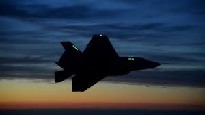
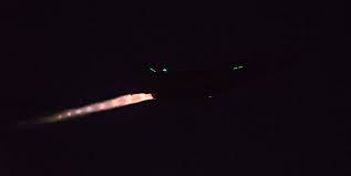
Now at night as you can see is very hard to see details, many details of F-35 have disappeared from our eyes

1572010840377.png

now see, you are seeing a F-35, the fuselage does not emit light but the engine does, you now can see why power density is important, the engine has high power density, emmits lots of light, the rest of the fuselage emits almost no light
1572011020476.png


Radar is the same, lots of light, you see the bump, easily you can see is round, no light it becomes invisible.


Stealth masking just use some basic laws to help low power density reflection to get more invisible

for a radar close to the F-35 the inlet is as visible as the next picture, far from it, it is like the F-35 at night
1572011369024.png
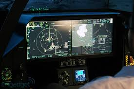
now at night the pilot has LCD screens with light but from the previous pictures you can not see the light they emit at night and from far away

1572012236013.png thus power density plays the biggest role in stealth
 
Last edited:
Why do some still insist on using analogies from the visual spectrum for radar behavior, considering the orders of magnitude difference in wavelength?

Because it is easier to illustrate and relate and MOST people will understand it a bit better that way.

Having two experts "vigorously discuss" (argue :) ) the mechanics while amusing to watch/listen to did not in fact enhance my knowledge any faster of the subject which also didn't help me pass the next test to move on in studying the subject :)

Randy
 
Agreed. Ronny or Pegasus's posts aren't helpful to the topic so I've split to a new topic. I'd missed Deino's post in a sea of irrelevancy.
 
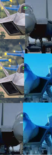
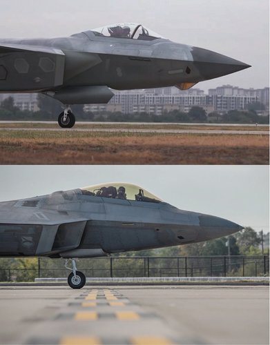
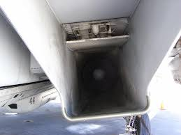
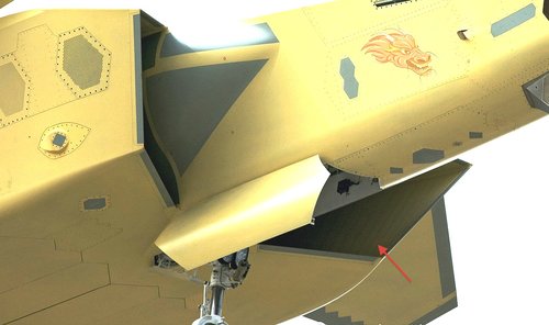
Looking inside that air intake, one can see rows of rivets or holes ? if these are holes , then the exit could be the hexagon shapes ?
And the first hexagon shape does not project in the inside, so if it's an inlet then the airflow must get out further back in the main intake or elsewhere.

Sans titre.jpg
 
I noticed that too, they look like rivets to me. A BL bleed inside the inlet would probably be on the fuselage side (i.e. the compression surface), as that's where the adverse pressure from the shocks would affect the boundary layer. Frequently the BL air removed by the bleed is ducted some distance away to a convenient location for an outlet, so the fact that there is nothing visible on the interior of the duct directly opposite the hexagons doesn't mean they aren't bleed openings. For example, on the Su-27 the BL bleed (slot + perforations) are on the ramps inside the roof of the intake while the outlets are on the exterior of the left and right side wall.
 
Fortunately big liz sent me to her second school of technical training, hence emboldened I shall try to enter the fray.....

Stealth-cautious and surreptitious action or movement.

The aim of stealth is, much the same as for camouflage.

In a perfect world camo will mean you, your tank, your aircraft will not be detected, while you complete your destructive mission.

In a less than perfect world, it will delay your detection, thus minimising the time for the enemy to respond. Increasing the probability of success, and survival.

A few comments on the points made.

Stealth can be detected with a big enough radar. True. Assuming we are in a shooting war, how long do you think your huge super doper radar is going to have before it eats a missile, either emission or gps guided, as huge radars don’t move much, except ship based. Alternatively I will simply knock out your super huge power station.

‘Passive radars’ this came up on another site, germans tracking f35 in peacetime. Upon looking at the radar companies website, it becomes apparent it needed tv, fm radio or similar transmitters operating, and mapped to the detector. Again in a hot war your enemy isn’t going to let you keep transmitting tv, it’s not a human right. The system doesn’t work from phone masts etc.

You can fly here, if your over my city we will see you, etc.

Any military flight, using a stealth aircraft, in a hostile- meaning peer or near peer, is going to be planned ‘to death’. It’s probably already planned. I’m not going to zoom in with my f35 until I have zapped as much of your radars, tv transmitters, power stations etc as I can.

Then I’m going to have stand off jamming, drones, etc, and my manned aircraft is only going to get close enough to launch its guided weapon.

Pretty unlikely I’m coming over your city, with my f35.

F22 can be detected by su35- at 40km. Uhu, which means f22 can detect the su35 ( because his radar is emitting) at maybe 160kms, so he changes course and avoids detection, thus completing his mission to destroy the su35 base fuel dump. I know which aircraft and force I would sign up to.

There’s my two peneth worth.
I agree with you totally, however the Su-35 and Su-57 are based upon speed and manoeuvrability.


the DSI intake is for lower speeds, speeds of Mach 1.7 while the Russian patent claims Su-57 has an intake for speeds up to Mach 3.


The six generation fighters are ought to have less aerodynamic controls, BVR missiles do not have a kill rate of 100% specially if the aircraft firing them can not recognize if the target is an authentic friend or foe.


What i mean is Su-57 is designed to supercruise very likely at high speeds up to Mach 1.8 and it has very likely top speeds of Mach 2.4, if materials allow it.

What are the chances F-22 will surprise a Su-57? in my opinion BVR missiles are limited in number on 5th generation aircraft, I think 6 BVR AAM will not hit 100% of the time and these aircraft will carry 2 short range AAM, in my opinion these aircraft either use speed and go back after firing their BVR missiles and go home just keeping the 2 short range in the case they need them.


So then is why the caret intake of Su-57 will allow better acceleration and faster speeds than using DSI


I agree with Ronny that at lower speeds the DSI has more practicality, simplicity, so for a lower speed aircraft like F-35 remain unseen will be more important than for Su-35 or Su-57, Stealth needs always speed, because the stealth aircraft needs to enter and exit the area where it can be detected quickly to minimize loses.


J-20 also must fly at around Mach 1.6, and the porous intake holes located in the intake cowl very likely are ways to bleed boundary layer and very likely increase pressure recovery and allow it higher speeds of Mach 1.8 or mach 2, but i do not think it will be as efficient as PAKFA aka Su-57, thus i think DSI suffer limitations in speed that force F-35 or J-20 to remain unseen longer than fighters like Su-57


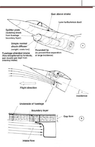
The diverterless supersonic inlet (DSI) of the Lockheed Martin joint strike fighter (JSF), which operates mostly at transonic speeds, has been designed taking whatever is mentioned above into enough account. Fundamental researches on this inlet configuration have been continued since the mid-1990s.
The inlet cowl lips are so designed as to allow most of boundary layer flow to spill out of the aft notch. The DSI structure complexity has been greatly reduced by the removal of moving parts, a boundary layer diverter and a bleed or bypass system thus decreasing the aircraft’s empty weight, production cost, and requirements of maintenance-supporting equipment[1-2].

the effects of the free stream Mach number on the mass flow coefficient and total pressure recovery when D = 0º and E = 0º. As the free stream Mach number increases, the mass flow coefficient decreases, and, after reaching the minimum at Mach number 1.000, it increases. Fig.7 also shows that the total pressure rises and remains constant when the free stream Mach number is up from 0.600 to 1.000, and, afterwards, drops sharply while the free stream Mach number approaches the supersonic.

4 Conclusions A wind-tunnel test of a ventral diverterless high offset S-shaped inlet has been carried out to investigate the aerodynamic characteristics at transonic speeds. Some conclusions can be drawn as follows: (1) There is a large region of low total pressure at the lower part of the inlet exit caused by the counter-rotating vortices formed at the second turn of the S-shaped duct. (2) The performances of the inlet reach almost the highest at Mach number 1.000. This renders the propulsion system able to work with high efficiency in terms of aerodynamics. (3) As the mass flow coefficient increases, the total pressure recovery decreases; the distortion increases at Ma0 = 0.850, but fluctuates at Ma0 = 1.000 and 1.534. (4) The total pressure recovery increases slowly first, and then remains unchanged as the Mach number rises from 0.600 to 1.000. (5) The performances of the inlet are generally insensitive to angles of attack from –4º to 9.4º and yaw angles from 0º to 8º at Mach number 0.850, and angles of attack from –2º to 6º and yaw angles from 0º to 5º at Mach number 1.534.

A Ventral Diverterless High Offset S-shaped Inlet at Transonic Speeds Xie Wenzhong*, Guo Rongwei College of Energy and Power Engineering, Nanjing University of Aeronautics and Astronautics, Nanjing 210016, China Received 13 September 2007; accepted 18 December 2007


Boundary-layer bleed in supersonic inlets is typically used to avoid boundary layer flow separation f_m adverse shock-wave/boundary-layer interactions and subsequent total pressure loss in the subsonic diffuser and to stabilize the normal shock


https://ntrs.nasa.gov/archive/nasa/casi.ntrs.nasa.gov/19950013353.pdf
 
Last edited:
I think pegasus's points on optimizing DSI for supersonic performance are highly relevant, however.

A big on-going mystery is the apparently lackluster nature of the J-20's maneuverability. Chinese fanboys usually claim that the PLAAF isn't going to give away the goods as to how agile the J-20 is, but we've been given a strip tease on the J-20's capabilities for years. Likewise, considering that the J-20 is scheduled to be re-engined, why not give enemies a false impression of the J-20's agility under the older Al-31 or WS-10 engines when the WS-15 is waiting in the wings?

Moreover, we know from the J-20's other characteristics than the J-20 SHOULD be relatively maneuverable; i.e, the wing loading is good and the T/W is around the same level as a F-35 at 60% fuel.

One possibility is that the DSI is just optimized for high speeds, i.e, the DSI bump is overly large and reduces air pressure at low subsonic speeds.

The VTech student analysis suggested that with 21.77 meters length and about 13.1 diameter (most accurate numbers are currently about 20.4m length with 12.9 meters wingspan) a shock probe forms at about Mach 2.1, and their estimate is that the J-20 is a Mach 2.1 to Mach 2.5 fighter.

Optimizing a DSI for middling Mach 2 regimes, on the other hand, implies slouch at subsonic speeds.

Something I've pointed out is that with moderate J-20 weight numbers, the J-20 could end up having absurd 1.45 to 1.6 T/W ratios at 60% fuel if WS-10s come to the 180kn range. That implies that the J-20 could simply rely on surplus power at subsonic speeds instead of focusing on high pressure recovery now.

If you're stuck working with poor engines in the 125kn-145kn range when you want a 180kn engine, you have two workarounds. First, you can optimize for low-speed maneuverability a la the Su-57, while sacrificing high-speed performance. When the upgraded engines come in, you now improve both in maneuverability and high-speed performance. Second, you can optimize for high-speed performance while sacrificing low-speed maneuverability.

The question then comes to, when you're running a modern stealth fighter in an arena where most competitors are running 4th generation aircraft, do you optimize for high-speed performance or do you optimize for low-speed performance? Remember, at the end of the day, the J-20 is currently slated to be equipped with only 6 missiles, two of them dogfight missiles. If you assume it'll take 2 missiles to knock down an enemy plane, would you prefer to dogfight or would you prefer BVR combat, where 5th generation aircraft excel in?
 
Ronny ask you self this
With light it is possible to see the intake bump, light is a shorter wave length than the wavelengths used by radar, your eyes can see the bump, you have no problem, now the problem with these theoretical graphs or concept you are using is you are not using more practical examples with light, the creeping wave exists simply because at each and every new tangent, light is diffracting, in fact splitting into new directions every time it moves from one tangent to the next tangent in the 180 degrees of shadow of a cylinder
If your theory is correct or in other words if wave can always diffracting a whole circle around the object regardless of the wavelength size compare to the object, then you will be able to see with your eye not just the DSI cowl but also what behind it. You will actually always able to see an object behind a corner. And when you cover the sun with a soccer ball 1 cm from your eye, you will still see the sun. None of that is possible.


any electromagnetic wave will diffract, it will enter into the shadow zone
[/QUOTE]
Yes but how much it can enter the shadow zone depend on the size of the wavelength versus the size of the object.
Seriously though, just think about all the questions I mentioned earlier
Why they have to divide RCS of an object into 3 separate regions to calculate: Optical/Mie/Rayleigh?.
Why the double-slit experiment is done with slits instead of a large gap?.
Why very low-frequency radar is considered better against stealth aircraft than high frequency radar?.

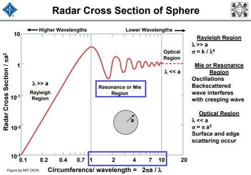
Look at this measured data why RCS of a sphere only fluctuated significantly when the wavelength approaches its radius?
156299-43555c4c8cd95f327ac2b37305877fcf.png
 
[
If your theory is correct or in other words if wave can always diffracting a whole circle around the object regardless of the wavelength size compare to the object, then you will be able to see with your eye not just the DSI cowl but also what behind it. You will actually always able to see an object behind a corner. And when you cover the sun with a soccer ball 1 cm from your eye, you will still see the sun. None of that is possible.


Yes but how much it can enter the shadow zone depend on the size of the wavelength versus the size of the object.
Seriously though, just think about all the questions I mentioned earlier
Why they have to divide RCS of an object into 3 separate regions to calculate: Optical/Mie/Rayleigh?.
Why the double-slit experiment is done with slits instead of a large gap?.
Why very low-frequency radar is considered better against stealth aircraft than high frequency radar?.

Look at this measured data why RCS of a sphere only fluctuated significantly when the wavelength approaches its radius?
Ronny you did not read well the nasa document? see what it says

CREEPING-WAVE DIFFRACTION CONCEPT When a wave is incident upon an opaque object which is large compared to the wavelength, a shadow is formed. However, some radiation penetrates into the shadow region due to diffracted rays as shown in figure 5. (See refs. 12 to 16.) These rays are produced by incident rays which are tangent to the surface of the body. Each tangent ray splits at the point of tangency with one part continuing along the path of the incident ray and the other traveling along a geodesic on the surface of the body. At each following point, it splits again with one part traveling along the geodesic and the other reradiating along a tangent to the geodesic. rays are produced, one of which is reradiated at each point of the geodesic. These waves traveling around the opaque body have been designated as creeping waves introduced first by Franz and Deppermann (ref. 12) for the interpretation of scalar diffraction by circular cylinders and spheres

The light as well radar frequencies and wavelength do fill those requirements

1572065063370.png

1572065178453.png
1572065478904.png
1572065510520.png
see what the Chinese document says about DSI intake like the one of J-10 but also applies to J-20:


the effects of the free stream Mach number on the mass flow coefficient and total pressure recovery when D = 0º and E = 0º. As the free stream Mach number increases, the mass flow coefficient decreases, and, after reaching the minimum at Mach number 1.000, it increases. Fig.7 also shows that the total pressure rises and remains constant when the free stream Mach number is up from 0.600 to 1.000, and, afterwards, drops sharply while the free stream Mach number approaches the supersonic

4 Conclusions A wind-tunnel test of a ventral diverterless high offset S-shaped inlet has been carried out to investigate the aerodynamic characteristics at transonic speeds. Some conclusions can be drawn as follows: (1) There is a large region of low total pressure at the lower part of the inlet exit caused by the counter-rotating vortices formed at the second turn of the S-shaped duct. (2) The performances of the inlet reach almost the highest at Mach number 1.000. This renders the propulsion system able to work with high efficiency in terms of aerodynamics. (3) As the mass flow coefficient increases, the total pressure recovery decreases; the distortion increases at Ma0 = 0.850, but fluctuates at Ma0 = 1.000 and 1.534. (4) The total pressure recovery increases slowly first, and then remains unchanged as the Mach number rises from 0.600 to 1.000. (5) The performances of the inlet are generally insensitive to angles of attack from –4º to 9.4º and yaw angles from 0º to 8º at Mach number 0.850, and angles of attack from –2º to 6º and yaw angles from 0º to 5º at Mach number 1.534.

A Ventral Diverterless High Offset S-shaped Inlet at Transonic Speeds Xie Wenzhong*, Guo Rongwei College of Energy and Power Engineering, Nanjing University of Aeronautics and Astronautics, Nanjing 210016, China Received 13 September 2007; accepted 18 December 2007


Boundary-layer bleed in supersonic inlets is typically used to avoid boundary layer flow separation f_m adverse shock-wave/boundary-layer interactions and subsequent total pressure loss in the subsonic diffuser and to stabilize the normal shock


1572066423605.png

1572067430955.png

https://ntrs.nasa.gov/archive/nasa/casi.ntrs.nasa.gov/19950013353.pdf

Basically the DSI intake loses pressure recovery, becoming less capable as the intake goes supersonic
 
Last edited:
radars by increasing the power density will see stealth aircraft well.

No, they will not. You can't change the laws of physics.
Double the power output and you get a less than 20% increase in detection range under ideal conditions.

RCS is the most important variable in the radar range equation. The aircraft always has the advantage.
 
No, they will not. You can't change the laws of physics.
Double the power output and you get a less than 20% increase in detection range under ideal conditions.

RCS is the most important variable in the radar range equation. The aircraft always has the advantage.
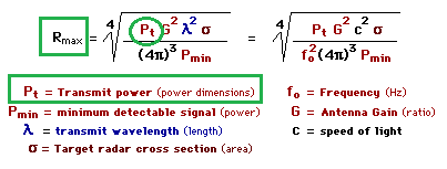
1572082746337.png


The equation does not say that exactly because as any equation everything depends in the values you input on it

it says


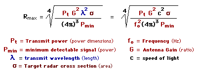
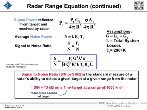
1572083115138.png

Radar range equation for search (S/N = signal to noise ratio) • S/N of target can be enhanced by – Higher transmitted power Pav – Lower system losses L – Minimize system temperature T The design of radar transmitter/receiver affects these three parameters directly Pav = average power Αe = antenna area ts = scan time for Ω Pav = average power σ = radar cross section Ω = solid angle searched R = target range Ts = system temperature L = system loss
 
Last edited:
I think pegasus's points on optimizing DSI for supersonic performance are highly relevant, however.

A big on-going mystery is the apparently lackluster nature of the J-20's maneuverability. Chinese fanboys usually claim that the PLAAF isn't going to give away the goods as to how agile the J-20 is, but we've been given a strip tease on the J-20's capabilities for years. Likewise, considering that the J-20 is scheduled to be re-engined, why not give enemies a false impression of the J-20's agility under the older Al-31 or WS-10 engines when the WS-15 is waiting in the wings?

Moreover, we know from the J-20's other characteristics than the J-20 SHOULD be relatively maneuverable; i.e, the wing loading is good and the T/W is around the same level as a F-35 at 60% fuel.

One possibility is that the DSI is just optimized for high speeds, i.e, the DSI bump is overly large and reduces air pressure at low subsonic speeds.

The VTech student analysis suggested that with 21.77 meters length and about 13.1 diameter (most accurate numbers are currently about 20.4m length with 12.9 meters wingspan) a shock probe forms at about Mach 2.1, and their estimate is that the J-20 is a Mach 2.1 to Mach 2.5 fighter.

Optimizing a DSI for middling Mach 2 regimes, on the other hand, implies slouch at subsonic speeds.

Something I've pointed out is that with moderate J-20 weight numbers, the J-20 could end up having absurd 1.45 to 1.6 T/W ratios at 60% fuel if WS-10s come to the 180kn range. That implies that the J-20 could simply rely on surplus power at subsonic speeds instead of focusing on high pressure recovery now.

If you're stuck working with poor engines in the 125kn-145kn range when you want a 180kn engine, you have two workarounds. First, you can optimize for low-speed maneuverability a la the Su-57, while sacrificing high-speed performance. When the upgraded engines come in, you now improve both in maneuverability and high-speed performance. Second, you can optimize for high-speed performance while sacrificing low-speed maneuverability.

The question then comes to, when you're running a modern stealth fighter in an arena where most competitors are running 4th generation aircraft, do you optimize for high-speed performance or do you optimize for low-speed performance? Remember, at the end of the day, the J-20 is currently slated to be equipped with only 6 missiles, two of them dogfight missiles. If you assume it'll take 2 missiles to knock down an enemy plane, would you prefer to dogfight or would you prefer BVR combat, where 5th generation aircraft excel in?

Do we currently have any reliable up-to-date sources re: the J-20’s current maneuverability and subsonic (and/or supersonic) performance?
If we do then such conjecture around the role of the DSI in those performance parameters may be warranted.
If not then this conjecture appears somewhat premature, with a lot of “...and if...” accumulating.
 
No disrespect but some contributors comments are still coming across as Russian-fan-boy ideas but now dressed up with extensive and somewhat pseudoscientific trappings. This may not be any intended or recognised by these contributors.
Why does everything seem to come back to the allegedly weakness of “stealth” versus “more powerful” radars, and the alleged superiority of variable inlets over DSI (and an alleged major flaws of DSIs)?
All of which nicely and conveniently tallies back to and with current Russian approaches versus everyone else’s (US, China etc.)
No offence is intended; I‘d be equally questioning of such conveniences if a contributor was doing the same re: US, UK etc.
(Other contributors can attest I have done do.)
 
It is a very narrow discussion, as I was trying to point out, theoretical super radars won’t last long. You go to war with what you have. I’m doubtful intake design will have a major impact upon the outcome of future conflicts, I’m also of the opinion that us, Russia, China, nato are all too powerful to have a conflict, it will all be proxy, flip flop enemies, or religious strife, where one persons stealth aircraft will be used as safe bomb trucks.
 
No disrespect but some contributors comments are still coming across as Russian-fan-boy ideas but now dressed up with extensive and somewhat pseudoscientific trappings. This may not be any intended or recognised by these contributors.
Why does everything seem to come back to the allegedly weakness of “stealth” versus “more powerful” radars, and the alleged superiority of variable inlets over DSI (and an alleged major flaws of DSIs)?
All of which nicely and conveniently tallies back to and with current Russian approaches versus everyone else’s (US, China etc.)
No offence is intended; I‘d be equally questioning of such conveniences if a contributor was doing the same re: US, UK etc.
(Other contributors can attest I have done do.)
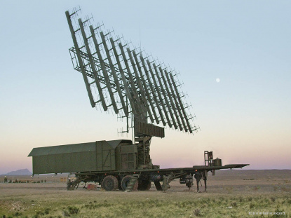
Rezonans-NE
Stealth air target early warning radar
Mission
The Rezonans-NE very high frequency counter-stealth early warning phased-array radar is designed to effectively detect a wide range of current and future air targets, including low-observable cruise and ballistic missiles, hypersonic aerial vehicles, as well as stealthy ones, in severe electronic countermeasures (ECM) and clutter environment.
Tasks
  • detect and track a wide range of air targets at long ranges, including small and stealthy ones;
  • automatically determine the location and motion parameters of air targets as well as classify them;
  • automatically provide designations to weapon systems;
  • generate and send information about the tracked targets for taking operational decisions;
  • analyze the ECM situation and automatically adjust to the actual ECM conditions.
http://roe.ru/eng/catalog/air-defen...uipment-for-air-target-detection/rezonans-ne/
 
It is a very narrow discussion, as I was trying to point out, theoretical super radars won’t last long. You go to war with what you have. I’m doubtful intake design will have a major impact upon the outcome of future conflicts, I’m also of the opinion that us, Russia, China, nato are all too powerful to have a conflict, it will all be proxy, flip flop enemies, or religious strife, where one persons stealth aircraft will be used as safe bomb trucks.

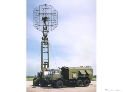
Nebo-SVU
Surveillance radar surface surveillance standby conditions 2D Radar
The Nebo-SVU radar is designed for use in Air Defence forces and provides:
  • automatic detection, positioning, and tracking of a wide range of current air targets, including ballistic and low-signature stealthy targets;
  • identification friend-or-foe interrogation;
  • location of active jammers;
  • target identification when operating as part of both advanced automated Air Defence command and control systems and non-automated control systems.
Radar design features:
  • an active electronically scanned array (AESA) with analog-to-digital data signal conversion in each array row;
Fighter-type target detection range (RCS=2,5 km²), at the flight altitude of, not less than, km:
500 m 60
10000 m 270
20000 m 360
 
No disrespect but some contributors comments are still coming across as Russian-fan-boy ideas but now dressed up with extensive and somewhat pseudoscientific trappings. This may not be any intended or recognised by these contributors.
Why does everything seem to come back to the allegedly weakness of “stealth” versus “more powerful” radars, and the alleged superiority of variable inlets over DSI (and an alleged major flaws of DSIs)?
All of which nicely and conveniently tallies back to and with current Russian approaches versus everyone else’s (US, China etc.)
No offence is intended; I‘d be equally questioning of such conveniences if a contributor was doing the same re: US, UK etc.
(Other contributors can attest I have done do.)
Rezonans-NE
Stealth air target early warning radar
Mission
The Rezonans-NE very high frequency counter-stealth early warning phased-array radar is designed to effectively detect a wide range of current and future air targets, including low-observable cruise and ballistic missiles, hypersonic aerial vehicles, as well as stealthy ones, in severe electronic countermeasures (ECM) and clutter environment.
Tasks
  • detect and track a wide range of air targets at long ranges, including small and stealthy ones;
  • automatically determine the location and motion parameters of air targets as well as classify them;
  • automatically provide designations to weapon systems;
  • generate and send information about the tracked targets for taking operational decisions;
  • analyze the ECM situation and automatically adjust to the actual ECM conditions.
http://roe.ru/eng/catalog/air-defen...uipment-for-air-target-detection/rezonans-ne/
Fixed site, 100m square. Unique visible layout. Gone in first 24 hours, simply because it has to be gone, so i’ll Send 20 tomahawks in, one will make it.

Next.
 
Ronny you did not read well the nasa document? see what it says
CREEPING-WAVE DIFFRACTION CONCEPT When a wave is incident upon an opaque object which is large compared to the wavelength, a shadow is formed.
The light as well radar frequencies and wavelength do fill those requirements
Yes I read it well and carefully.
If you actually paying attention, you will see that many time when I talked about creeping wave return and Mie region, I always said the wavelength size approach the size of object. Rather than the wave being bigger than the object. This was illustrated very clearly in the diagram I posted previously, specular return interfered with creeping wave return in Mie region, that what cause the RCS fluctuation
RCS2.PNG

On the otherhand if the wavelength size is bigger than the object, then the object will be in Rayleigh region, in that region there is little phase variation of the incident wave over the spatial extent of the scattering body, so each part of the target encounter the same incident field at each moment of time.You don't have a shadow region in that case. The situation is similar to a static field problem, with the exception that the incident field is changing in time. This quasi-static field builds up opposite charges at the ends of the body of the target.When the wavelength is much greater than the object circumference, in Rayleighregion, its cross section is proportional to 1.PNG where 2.PNG is the wavenumber. Consequently, although the radar cross section is small, it increases as the fourth power of frequency and sixth power of radius. The most notable characteristic of Rayleigh scattering is that cross section is proportional to the fourth power of the frequency

No, they will not. You can't change the laws of physics.
Double the power output and you get a less than 20% increase in detection range under ideal conditions.
RCS is the most important variable in the radar range equation. The aircraft always has the advantage.
The equation does not say that exactly because as any equation everything depends in the values you input on it
it says
Radar range equation for search (S/N = signal to noise ratio) • S/N of target can be enhanced by – Higher transmitted power Pav – Lower system losses L – Minimize system temperature T The design of radar transmitter/receiver affects these three parameters directly Pav = average power Αe = antenna area ts = scan time for Ω Pav = average power σ = radar cross section Ω = solid angle searched R = target range Ts = system temperature L = system loss
Actually, the equation say exactly what quellish said
1572082746337.png
From the equation we can see that detection range is proportional to fourth root of transmitting power.
if we double the power value, the fourth root of it is only 1.18 still, so with all other factors remain the same, double the power will give you 18% longer detection range.


see what the Chinese document says about DSI intake like the one of J-10 but also applies to J-20:
Basically the DSI intake loses pressure recovery, becoming less capable as the intake goes supersonic
I honestly don't see how all that are relevant to my comment about J-10 DSI vs F-4 variable inlet.
 
Last edited:
Fighter-type target detection range (RCS=2,5 km²), at the flight altitude of, not less than, km:
500 m 60
10000 m 270
20000 m 360
Detection range of only 60 km versus target at flight altitude of 500 meters is quite short. It will be very vulnerable to cruise missile such as Tomahawk,KEPD350, LRASM, JSM
 
Detection range of only 60 km versus target at flight altitude of 500 meters is quite short. It will be very vulnerable to cruise missile such as Tomahawk,KEPD350, LRASM, JSM
There are different radars for work against low flying targets, including 96L6-1 and 9S36. There is no win-all radar, different systems are meant for different work.
 
Ronny you did not read well the nasa document? see what it says
CREEPING-WAVE DIFFRACTION CONCEPT When a wave is incident upon an opaque object which is large compared to the wavelength, a shadow is formed.
The light as well radar frequencies and wavelength do fill those requirements
Yes I read it well and carefully.
If you actually paying attention, you will see that many time when I talked about creeping wave return and Mie region, I always said the wavelength size approach the size of object. Rather than the wave being bigger than the object. This was illustrated very clearly in the diagram I posted previously, specular return interfered with creeping wave return in Mie region, that what cause the RCS fluctuation
View attachment 620731

On the otherhand if the wavelength size is bigger than the object, then the object will be in Rayleigh region, in that region there is little phase variation of the incident wave over the spatial extent of the scattering body, so each part of the target encounter the same incident field at each moment of time.You don't have a shadow region in that case. The situation is similar to a static field problem, with the exception that the incident field is changing in time. This quasi-static field builds up opposite charges at the ends of the body of the target.When the wavelength is much greater than the object circumference, in Rayleighregion, its cross section is proportional to View attachment 620729 where View attachment 620730 is the wavenumber. Consequently, although the radar cross section is small, it increases as the fourth power of frequency and sixth power of radius. The most notable characteristic of Rayleigh scattering is that cross section is proportional to the fourth power of the frequency


Actually, the equation say exactly what quellish said
View attachment 620732
From the equation we can see that detection range is proportional to fourth root of transmitting power.
if we double the power value, the fourth root of it is only 1.18 still, so with all other factors remain the same, double the power will give you 18% longer detection range.


I honestly don't see how all that are relevant to my comment about J-10 DSI vs F-4 variable inlet.
Do you see that Pt can be any number? the equation does not say Stealth aircraft can not be detected, it simply says Pt is any number, give it any number the results change, you said light can not have creeping wave, the document says bigger object than the wavelength, F-16 is much much bigger than the wavelength of light or radar both are okay for creeping wave.


You can not see it is relevant simply because it says pressure recovery goes down and Mass flow goes up, do you see the trend? in order to stabilize the flow you need mechanic devices, when you lose pressure recovery you lose thrust, you lose thrust you lose acceleration, you lose more fuel simple like that, so it means a caret variable intake is better if you are going to fly faster than Mach 2
 
Last edited:
Detection range of only 60 km versus target at flight altitude of 500 meters is quite short. It will be very vulnerable to cruise missile such as Tomahawk,KEPD350, LRASM, JSM
1572121593117.png


1572121665036.png


it seems they work well especially since there are multiple sensors and types of radar
 
Last edited:
Fixed site, 100m square. Unique visible layout. Gone in first 24 hours, simply because it has to be gone, so i’ll Send 20 tomahawks in, one will make it.

Next.

1572122269112.png
1572123711109.png


the system is not fixed it works with other radars they are called radar netwoks it is like an onion multi layered

1572122728881.png


basically you will spend 100 missiles if you are lucky, because there are things called submarines and aircraft interceptors so a multilayered defence system will stop most of your attacks and mobile system will make even for stealth aircraft hard to enter.


You system only works if you attack a single radar without a network

1572122865146.png
 
Last edited:
Fixed site, 100m square. Unique visible layout. Gone in first 24 hours, simply because it has to be gone, so i’ll Send 20 tomahawks in, one will make it.

Next.

View attachment 620736
View attachment 620739


the system is not fixed it works with other radars they are called radar netwoks it is like an onion multi layered

View attachment 620737


basically you will spend 100 missiles if you are lucky, because there are things called submarines and aircraft interceptors so a multilayered defence system will stop most of your attacks and mobile system will make even for stealth aircraft hard to enter.


You system only works if you attack a single radar without a network

View attachment 620738
The radar consisting of the four modules controls the 360-degree sector and occupies a 100 x 100 m area.

Clearly states it’s fixed site, the picture on their site shows a fixed radar system, not the truck mounted one you have pictured.
Your onion will be peeled, seriously these claims may work with the chief buyer for Syrian Air Force, not so much for me.

100 missiles, I don’t think, west didnt spend this many on Iraq.
First you are avoiding the question can stealth aircraft be detected? answer yes; it is not who played better its assets like in Serbia, Irak or Yugoslavia.


It says you can detect stealth aircraft, in fact i will put it better, like Israel did in 1967, you can destroy aircraft in their bases just to render stealth aircraft useless.

Remember each new type recently are built in lower numbers.


Now the topic is not who is going to beat who, but rather if stealth is good enough to detect Stealth Intakes such as Caret or DSI types.

All the formulas i have given do not say stealth aircraft can not be detected.

Furthermore we are discussing if DSI is worthed at high speeds, the aerodynamic answer is no, the design number of an intake after 600 km/h requires some type of boundary layer bleed or diverter. design number of an intake limits the range of speeds it will be used, design speed of an intake means you can not have an intake type good for all speeds but rather just to some speed ranges.

Therefore there are intake types with variable geometry to control mass flow to the engine


The equations say given the right numbers you will detect any aircraft.

The limitation is how much electricity can generate an aircraft and the radar constraigns of temperature and loses.


So yes, some aircraft have weak radars, Stealth aircraft can fly far from aircraft with radars with low power density and are not going to be detected.

However today we have smarter aircraft that share information, so does not matter, F-35 will detect J-20 or Su-57 simply because the interconnectivity of the sensors, the plane that will survive will be the one that can avoid being hit, to do that you need stealth, speed and good avionics.

remember DSI intakes have stealth and performance constraigns too.
 
Last edited:

Similar threads

Back
Top Bottom