overscan (PaulMM)

Administrator
Staff member
Joined
27 December 2005
Messages
16,279
Reaction score
18,445
A-12 press pack, courtesy of flateric
 

Attachments

  • A-12text.jpg
    A-12text.jpg
    186.3 KB · Views: 3,873
  • A-12a.jpg
    A-12a.jpg
    94.4 KB · Views: 3,567
  • A-12b.jpg
    A-12b.jpg
    97.3 KB · Views: 3,168
  • A-12c.jpg
    A-12c.jpg
    68.9 KB · Views: 3,529
A-12 display model courtesy of Ian Maddock
 

Attachments

  • A-12_1a.jpg
    A-12_1a.jpg
    18.3 KB · Views: 695
  • A-12_1b.jpg
    A-12_1b.jpg
    21.1 KB · Views: 773
  • A-12_1c.jpg
    A-12_1c.jpg
    15.9 KB · Views: 736
  • A-12_1d.jpg
    A-12_1d.jpg
    13.7 KB · Views: 682
A good A-12 website, JIC anyone didn't know about it. It has alot of pics of the full scale mockup, which has the proper canopy shape (As opposed to the models incorrect canopy shape) and you can see the inlet vanes/baffles behind the plexiglas, for good airflow control and to shield the engine faces.
 
I should add also that the first model pics that Overscan posted are in-house MDC/GD model from ca.1990, second pics series is a limited run model made for A-12 government litigation team using first model as a base - as well as set of contractor's declassified drawings.

As Sundog correctly mentioned, many models' details are not quite complify to the artist's renditions and to 'ultimate' desktop model - I mean full-size A-12 mock-up, which I'm considering 'source code' for any modelling effort.

BTW, do anyone knows current state of A-12 full-size mock-up?

Also, if someone do have this AWST issue ca.1990(91) with a beefy several-page article with first A-12 renditions published, I'll be happy if you can share it. I've just found out what our State Scientific&Techniclal Library does with magazine backissues....after 10 years...they throw it away...idiots...
 
Good work dear overscan,

I have also an artistic picture to the rival proposal to A-12,
it was twin engined two seat canard aircraft project,and
the wing was look like Douglas F4D wing.
 
Hesham, please can you post it? My first impression was that you are speaking about what-if drawing from Stealth Warplanes, but after checking I realised, that it is not a canard.
 
Hesham,

On Skunk Works, the first 50 years there are some designs of its AF/X proposals:

Lockheed/Boeing
Grumman/Lockheed
Rockwell/Lockheed

Grumman/Lockheed has canards, but I can't see the wing plan...

Are you talking about this?
 
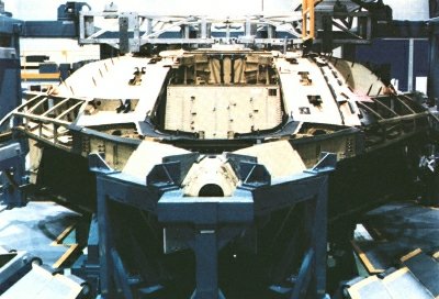
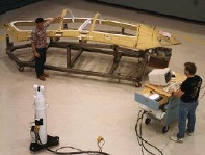
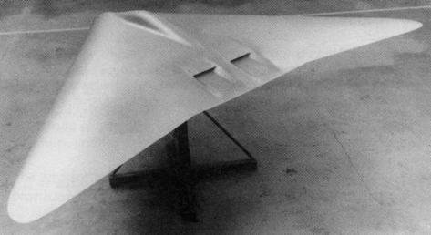
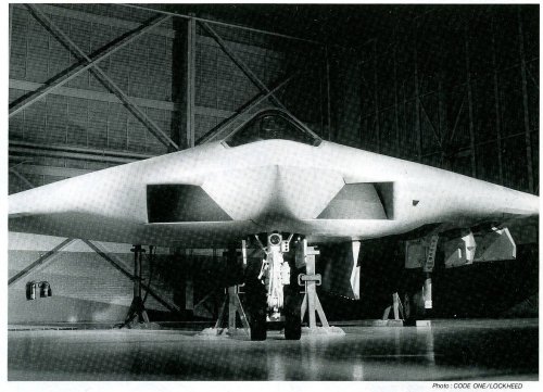
The full scale Mock-Up, I think, is in a museum in Texas.

Also, if anyone has the book, Billion Dollar Blunder, their is a pic of the model of the Northrop design for the ATA program. It looks like a smaller version of the B-2 (The planform is more like the original B-2 layout, with a smaller aspect ratio) and the wingtips would bend up vertically for greater stability when the gear was extended.

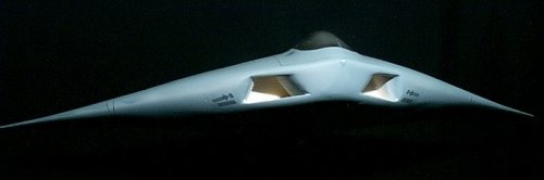
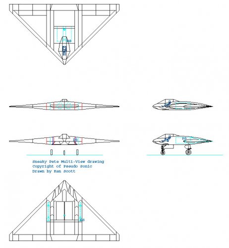
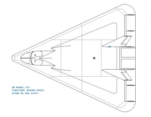
I would love to 3D model this plane, but it has so many subtle curves, without good cross section drawings it would be about impossible to get it right.

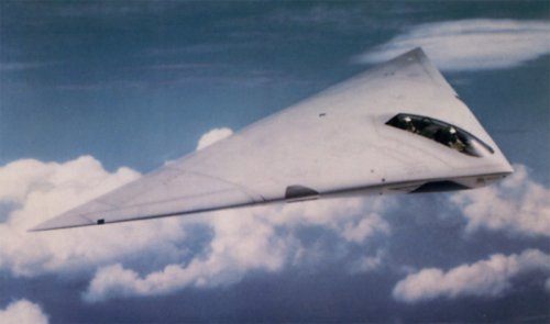
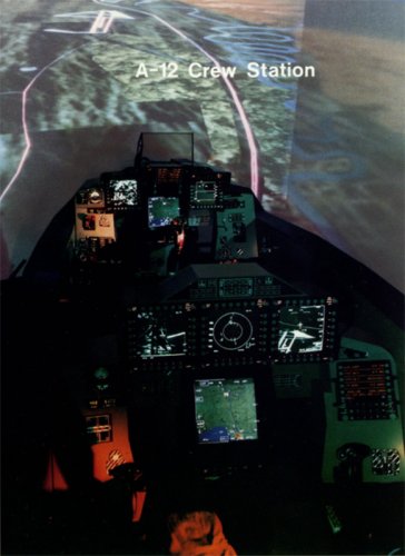
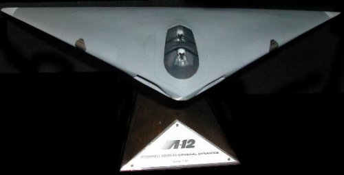
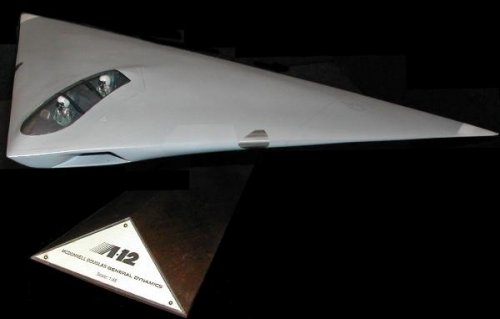
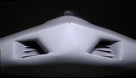
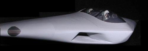
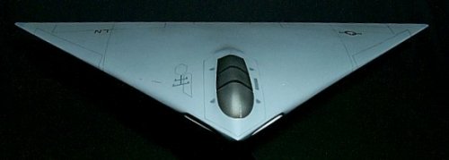
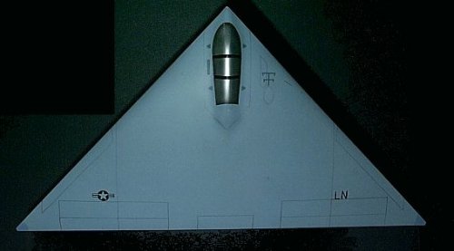
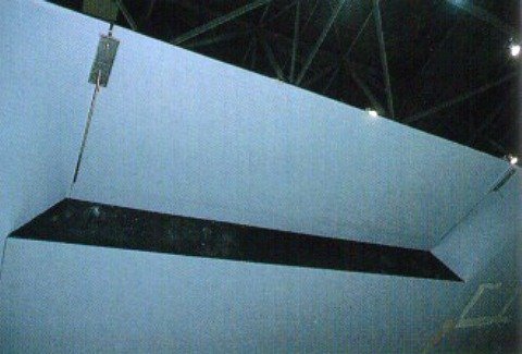
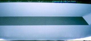
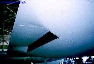
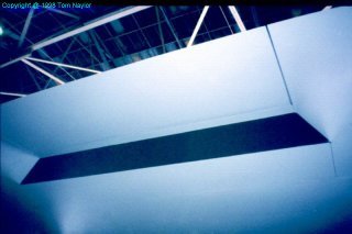
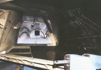
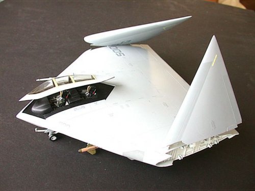
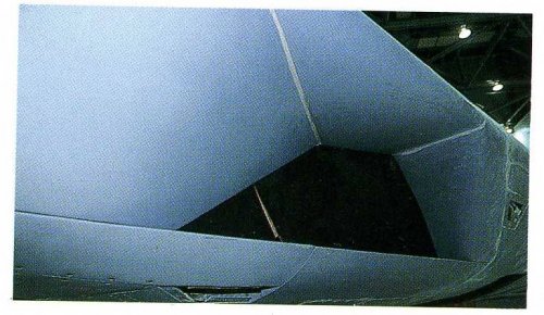
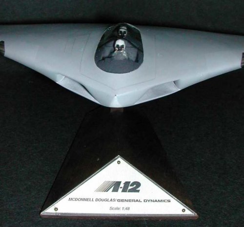
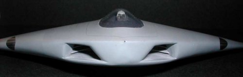
BTW, Overscan, that first "official" model for GD-McDD that has the cockpit modeled, is there any chance you can get a pic of the lower back exhaust area? I'm just curious if what is on that model is what is also shown on the full scale mock-up, because it's always been my understanding that it is still classified.

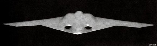
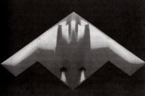
Also, an interesting side note, the Air Force version was to have the exhaust above the wing, not below. If you recall the Navy was supposed to get a version of the ATF and the Air Force a version of the ATA. The Air Force told the Navy that with stealth they wouldn't need to penetrate below the RADAR OTD the way A-6's did, so they could put the exhaust on the top so it was shielded from below. But the Navy felt they needed to perform low level penetration so they kept them on the bottom to shield them from above. At least that's what was said. I think it actually had more to do with the exhaust sytem.

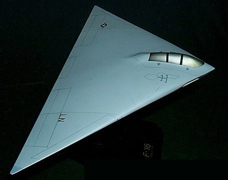
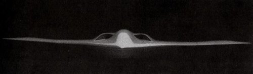
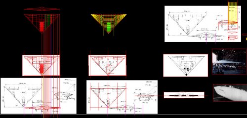
In one of my old AIAA Aerospace America magazines they had a CFD image of a "Delta Shaped Flying Wing" that looked remarkably like the A-12 in planform and in the CFD pic, the exhaust (Also in the same location as on the A-12) is shown vectored down and forward about 30 degrees and slightly angled out from centerline, hitting the ground/deck and bouncing back up under the wing as if to act as a "thrust cushion." I've often wondered if that was a feature the A-12 had to reduce the impact forces at landing and was why the noxzze(s) were classified.
 
Sundog, to my sorrow, we don't have pics of official model exaust...but look, Habu2 site have at least four photos of full-size mock-up exaust area.
 

Attachments

  • a12_c05.jpg
    a12_c05.jpg
    39.9 KB · Views: 461
  • 003_23.jpg
    003_23.jpg
    6.7 KB · Views: 455
  • 003_16.jpg
    003_16.jpg
    11.1 KB · Views: 513
  • 003_14.jpg
    003_14.jpg
    12.9 KB · Views: 640
Sundog said:
Also, if anyone has the book, Billion Dollar Blunder, their is a pic of the model of the Northrop design for the ATA program. It looks like a smaller version of the B-2 (The planform is more like the original B-2 layout, with a smaller aspect ratio) and the wingtips would bend up vertically for greater stability when the gear was extended.

Here's Northrop ATA proposal from the great James P. Stevenson's 'The $5 Billion Misunderstanding: The Collapse of the Navy’s A-12 Stealth Bomber Program'.
 

Attachments

  • northrop_ata_front1.jpg
    northrop_ata_front1.jpg
    11.8 KB · Views: 976
  • northrop_ata_rear1.jpg
    northrop_ata_rear1.jpg
    12.7 KB · Views: 1,010
  • northrop_ata_top1.jpg
    northrop_ata_top1.jpg
    41.7 KB · Views: 1,167
Some rare A-12 production photos (not sure of this is real a/c or mock-up)
 

Attachments

  • rightintake.jpg
    rightintake.jpg
    64.2 KB · Views: 1,563
  • rfwd.jpg
    rfwd.jpg
    116.8 KB · Views: 1,471
  • pl383.jpg
    pl383.jpg
    11.8 KB · Views: 1,673
Regarding the other ATA contenders I only have these two pictures ... the first from the FLUG Revue (issue ??) saying it shows a Boeing/Rockwell design and another one without any source !

PS ... + a wonderful build Model in 1/48 scale ....

Deino
 

Attachments

  • ATA maybe.JPG
    ATA maybe.JPG
    56 KB · Views: 1,843
  • ATA maybe 2.jpg
    ATA maybe 2.jpg
    51 KB · Views: 1,879
  • ATA A-12 Avenger 1-48 kit - 14.jpg
    ATA A-12 Avenger 1-48 kit - 14.jpg
    38.9 KB · Views: 1,357
My dears,

first sorry, I have not scanner now,second I mean the
Grumman/Northrop team first proposal,and I don't know
if Lockheed joint them later or not,but if dear Pometablava
have a drawing to Grumman/Lockheed please send it,and
I will tell you if it is like my picture or not.
 
I think pometablava meant this:

http://www.hitechweb.genezis.eu/stealth4.files/AFX1.jpg

There was not Grumman/Northrop consortium in AF/X program. I collected nearly all designs and they are here:

http://www.hitechweb.genezis.eu/stealth4.htm

Hesham, you can take a look and probably there is the picture that you are reffering to.
 
Deino, thanks for the pictures. The first of them shows something similar that I have from forum member elider. The original drawing was lost, but he did a handmade drawing. But there are some differencies:

Bigger, more rounded nose similar to the aircraft Northrop aircraft used to
validate the B-2s stealth.

Side-by-side crew compartment and a different windscreen--similar to the A3 Navy aircraft or somewhat like a commercial airliner.

No bulge or sensor below the radome.

The long sensor housing on the lower body side is longer, thicker and
further back ( not as big as the E8 lower bulge but similar in shape)..

Intakes identical to Boeings TFX proposal.

Only one vertical tail and it had a shape like the B-29 (seriously).

Horizontal tails had B-29 contours as well, and did not have any downward
curve--they were flat.

Main wing was straight ( flat) for some distance from the main body, then
it turned downward at an ever increasing rate until the wingtips were
nearly pointing straight down.
 

Attachments

  • image006.jpg
    image006.jpg
    6.8 KB · Views: 694
dear pometablava,

where is the drawing of Grumman/Lockheed for AF/X.
 
Hello all
I don't know if this is the right place to ask: But I am searching for hi-res images of the A-12 avenger2 blueprints.
I know about the Habu-A12 site, but they are not exactly hi-res images...
Those are way too small..
I had contact with the museumowner(?) a few years ago, they have/had the blueprints of it. But they couldn't scan them, because of too much work involved and because of their size... I read in a thread here on this forum ( Yes, I did do a search for the A-12) that the museum is closed already...
Does someone know of another source for the blueprints?

cheers
 
I'm very sceptic about possibility to get them because many things were and stay classified of Flying Dorito. News that museum stuff ever had them is a breakthrough for me - you should have been using this rare chance if you still have his contacts.
 
Hey Gregory

Unfortunately, I lost the email-adress a few years ago...
Strange that a decent 3view didn't end up in some book..
 
Seems strange, yes, but so far it goes. All I've seen is a crap official 3-view. Koku-Fan had some nice cutaway drawings ca 1992 made from placards shown to magazine staff in FW.
 
Yes, these plus several other more detailied blocks with sizing.
 
BAROBA said:
Hello all
I don't know if this is the right place to ask: But I am searching for hi-res images of the A-12 avenger2 blueprints.
I know about the Habu-A12 site, but they are not exactly hi-res images...
Those are way too small..
I had contact with the museumowner(?) a few years ago, they have/had the blueprints of it. But they couldn't scan them, because of too much work involved and because of their size... I read in a thread here on this forum ( Yes, I did do a search for the A-12) that the museum is closed already...
Does someone know of another source for the blueprints?

More like the museum never got things completely together and never got built, let alone opened. The last B-36 is now elsewhere and I've been told that the A-12 mockup is now in the "storage area" at the north end of the plant here in Fort Worth. Most of the stories I've heard say that the exact 50/50 work sharing was a big mistake in that no one could make final decisions and lots of time and money got wasted on meetings to decide way too many things and too many things weren't coordinated until it was too late.
 
When one was talking about FW USAF Plant No.4 with a phrases like 'far north end' I had an impression we're talking about something a size of Darth Wader's Death Star or imperial battlecruiser - before I googled it...

I wonder why they just didn't pass/lease/sell mockup to USAF Museum.
 
Well, it's not quite that big, though the main assembly area is a mile long. The "dump" as at the extreme north end of the facility, up against the edge of Lake Worth. I suppose that if someone made them a decent offer, they'd likely be willing to give it over, but the offer has to be made. I suspect asking either the USAF Museum or the Museum of Naval Aviation would be worth trying. I suspect they'd be willing to give it over if the recipient would just handle the shipping.
 
Thanks Matej :)
The only part I needed is not on the image...
The exact shape of the inlet is a mystery, I can get it almost right, but never good.
Thanks for posting anyways :)

The A-12 mock-up just stands there and rots away? :s
Or is it protected against the weather?
 
You might want to check out the book, The $5 Billion Misunderstanding. because it has a pic of a "clear" model of the A-12 and you can sort of see the path and width of the intakes in top view. You know where the engine face is as well, and from the pics available you can see where the intakes are and put together a good enough model of it. BTW, pay close attention to the intake pic at the A-12 site where you see the plexiglass over it, as right behind that you can see the intake vanes/baffles that help hide the intake face.

The only thing I was wondering about the inlet is whether or not the lower lip "droops" for high alpha flight or to increase capture area at low speeds. Or if that piece is just a separate piece that wasn't blended well on the mockup.

I had started modeling the A-12 for FS9, but then went over to modeling the GD Model 100 single seat flying wing that supposedly flew. Although, I actually have seen drawings of another design called the GD Model 100. That other being a highly swept delta wing with all three apex's rounded, side by side seating, twin side by side engines, with a dorsal inlet behind the cockpit and twin canted tails (like on the F-35) with nozzles like on the YF-23. It looks to be an F-111 class aircraft in terms of size, but that's just based on what I've been able to put together based on different articles. I was working on a model of it for FS9 as well, but really haven't had the time to work on them.
 
Sundog said:
I had started modeling the A-12 for FS9, but then went over to modeling the GD Model 100 single seat flying wing that supposedly flew. Although, I actually have seen drawings of another design called the GD Model 100. That other being a highly swept delta wing with all three apex's rounded, side by side seating, twin side by side engines, with a dorsal inlet behind the cockpit and twin canted tails (like on the F-35) with nozzles like on the YF-23. It looks to be an F-111 class aircraft in terms of size, but that's just based on what I've been able to put together based on different articles. I was working on a model of it for FS9 as well, but really haven't had the time to work on them.
 

Attachments

  • image020.jpg
    image020.jpg
    13.5 KB · Views: 1,305
The A-12 mockup WAS at one time kept in a hanger Lockheed was letting a museum group use until they built a permanent facility. The mockup, along with a B-36 and a few other aircraft they had stored were suppose to go into their museum, which never happened. Lockheed took the hanger back a few years ago for the JSF program, and the Air Force took the B-36 and I'm not exactly sure what happened to the other aircraft.

I wish I'd gotten more pictures of the scale model they also built, It was pretty detailed as well. The museum usually brought that out at the local airshows. Too bad I don't live there locally, otherwise I might be able to find out something. :(
 
As of 08/06/2007 - "This aricraft <B-36> has been moved to the Pima Aerospace Museum, Tucson Arizona, but is not yet on display.
More info on Southwest Aerospace Museum rise and death http://aeroweb.brooklyn.cuny.edu/museums/tx/sam.htm

Here goes some shots og full-scale mockup and official GD desktop model that can give an idea of A-12 intake shapes (missing radar blockers seen at fully restored mockup at habu2 site). Note that their crosssections are definitely changing along the trakt with outer walls being vertical in a front view - l__\ _ /__l. Nose lower part reminds boat nose, so inner walls are V-shaped. Along the intake trakt, both walls become incrinated, forming /-\-shape.

Also goes my teenage attempt to draw A-12 in AutoCAD using KokuFan cutaways and all the sources available as references.
And, don't forget to share your attempts to draw it;)

Desktop model pics courtesy by Ian Maddock.
 

Attachments

  • 001.jpg
    001.jpg
    78.4 KB · Views: 1,119
  • MDC GD A-12 Avenger II Model (1).pdf
    22.5 KB · Views: 142
  • P0000296.jpg
    P0000296.jpg
    86.8 KB · Views: 509
  • Dscn0450.jpg
    Dscn0450.jpg
    37 KB · Views: 486
  • Dscn0430.jpg
    Dscn0430.jpg
    18.7 KB · Views: 964
  • a-12_tandem3.jpg
    a-12_tandem3.jpg
    15.9 KB · Views: 1,043
  • 002.jpg
    002.jpg
    323.8 KB · Views: 1,211
I'll have to make ACAD drawings I was doing into Jpegs to show how I was doing.

Matej, the plane you show above was the precursor to the flying wing version of the model 100 I have seen. Wasn't "pigeon" part of the code name of the plane you're showing? (It's in my books in the basement, I'm not running down to look it up now ;) )

The version with the rounded Apexes I'm talking about is a Delta Wing, not a flying wing and much larger.

Although I believe you did have at your website the top view of the wing variant I was going to model. The only pic available is a top view of it in Viet Nam era camouflage (Sneaky Pete) and the faceted canopy. There's also an artists rendering of that variant shown with a wing way too thin to be of any use. The artist should have at least looked up the diameter of the engines likely to be used in it and made the wing thick enough to house them. The artist also made the mistake of showing the exhaust on top and bottom of the wing. Since the model shows it on top, it wouldn't be on the bottom.

In fact, along those lines, the main difference between the USN A-12 and the USAF A-12 was that the USAF variant would have had the exhaust on the top surface of the wing, not the bottom.
 
OK,
Here are my drawings which are my copyright. The first is my rendition of Sneaky Pete. In some articles I have seen this design referenced as the GD Model 100.

The second pic is a larger F-111 sized aircraft that I have also heard referenced as the GD Model 100. It's only the top view because I haven't finished the other views yet.

The last is just a pic of the A-12 I was working on. I stopped, because I think you really do need good cross section drawings to get the "flat area" on the lower leading edge of the wing where the intakes are correct.

All of these are AutoCAD pics.
 

Attachments

  • SP-1.jpg
    SP-1.jpg
    57.7 KB · Views: 1,093
  • Model-100-2.jpg
    Model-100-2.jpg
    45.1 KB · Views: 1,068
  • A12-ref.jpg
    A12-ref.jpg
    151 KB · Views: 1,085

Similar threads

Back
Top Bottom