
You are using an out of date browser. It may not display this or other websites correctly.
You should upgrade or use an alternative browser.
You should upgrade or use an alternative browser.
Merriman's Submarine Modelling Masterclass
- Thread starter merriman
- Start date


- Joined
- 18 March 2013
- Messages
- 978
- Reaction score
- 2,857
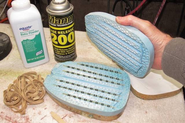
DISNEY NAUTILUS SPEED INDICATOR
That strange looking rotating spiral thingamabob tucked within an open section of the forward, lower keel of Nemo's NAUTILUS. Ever wonder what it's function was? 'Jake, when he first saw the movie at age 12 thought the thingamabob was some sort of auxiliary propulsion device.
Me? When I was a kid, and saw the movie with my parents, thought it was some kind of rock/coral crusher.
The thing is in fact an 'Archimedes Screw' and such things can either be a propulsive device – a propeller, imparting motion to a fluid to thrust its way through that fluid. Or, it can be a force generator – a turbine, set in motion to do work by a fluid running through it.
In fact, what we youngsters failed to grasp, was that the little Archimedes screw beneath nautilus was a turbine, its job to produce a torque who's force was proportionate to the speed of the submarine through the water; a speedometer. Analogous to today's, speed-log used by modern ships and submarines to accurately measure the speed of the vessel through water.
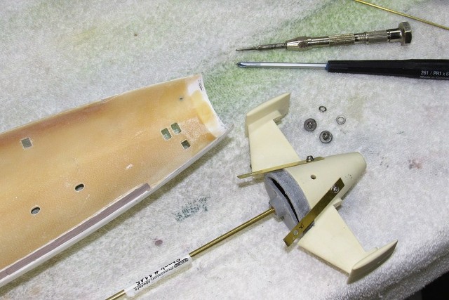
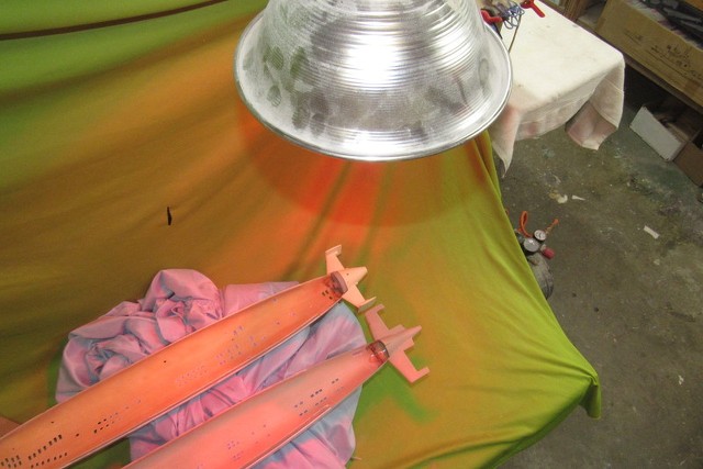
Decades ago, Ray Mason produced beautiful GRP and resin kits of the Disney NAUTILUS. I got one of them. But after years of procrastination, I gave it to my buddy, David 'Jake' Jacobson, a fellow retired Torpedoman's Mate. However, nearing completion of the kits assembly found that either I or he had lost the kits Archimedes screw part. So, needing one to complete the model, Jake came to me for some help to scratch build a replacement part.
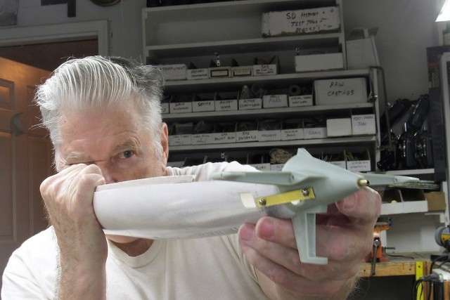
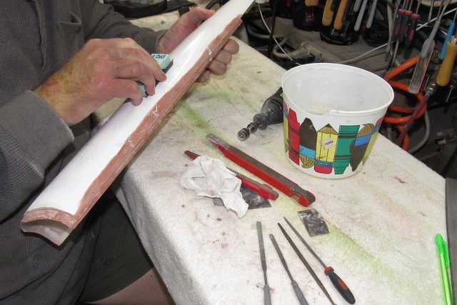
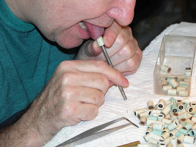
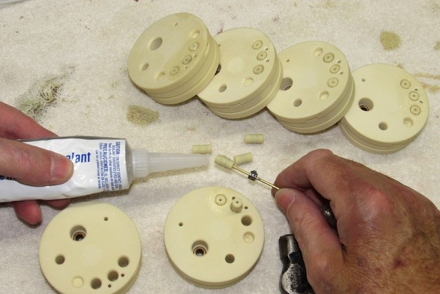
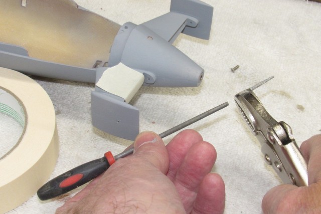
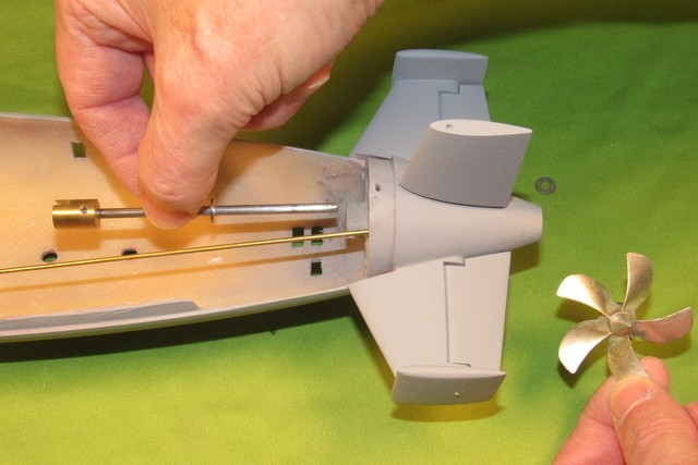
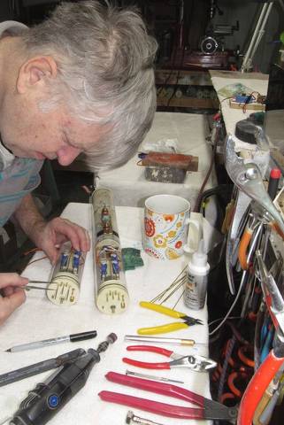
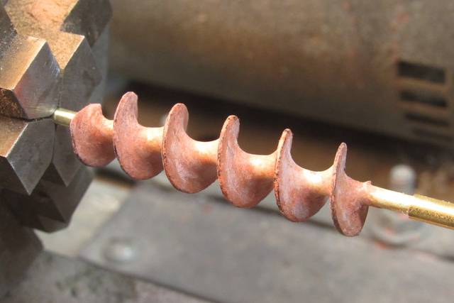
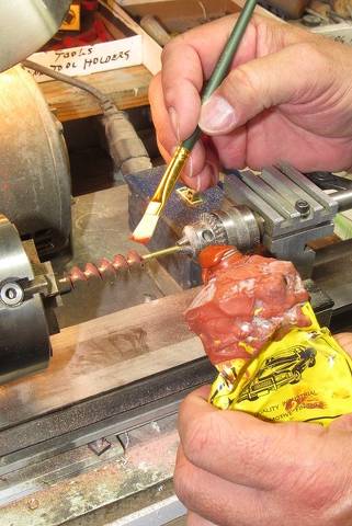
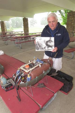
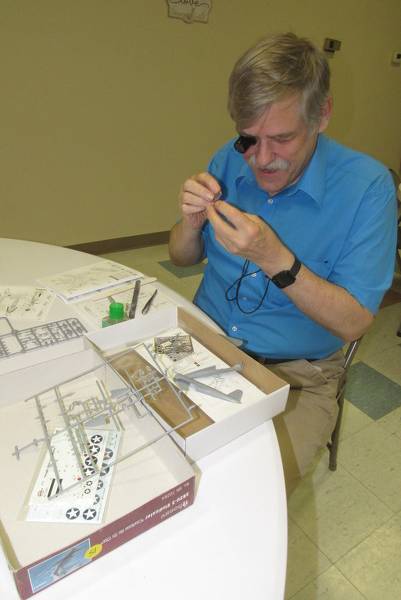
When it comes to kit assembly or scratch-building Jake is no slouch. However, creation of this tightly wound helical 'cork-screw' baffled him. So, he came over and we spent the better part of a day making one. I put tank-boy (he's a mover-shaker in the combat r/c tank world) to work producing the missing part. Notice his eager enthusiasm!... the idiot thought I was going to do all the work.
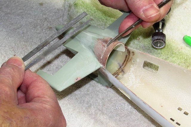
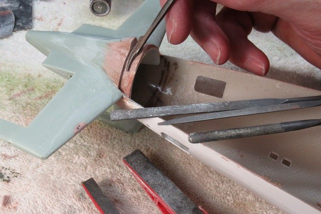
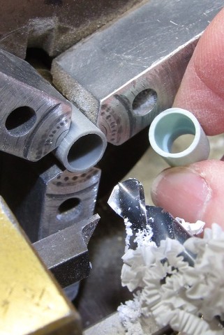
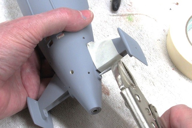
We used the lathe chuck and tail-stock only to hold the work steady as we used a round file to cute the channels between each 'blade' of the helical screw. The machine was NEVER turned on. By rotating the chuck by hand this 'rotary holding jig' permitted us to file away one portion, rotate the work as required, and continue with the filing till the job was completed.

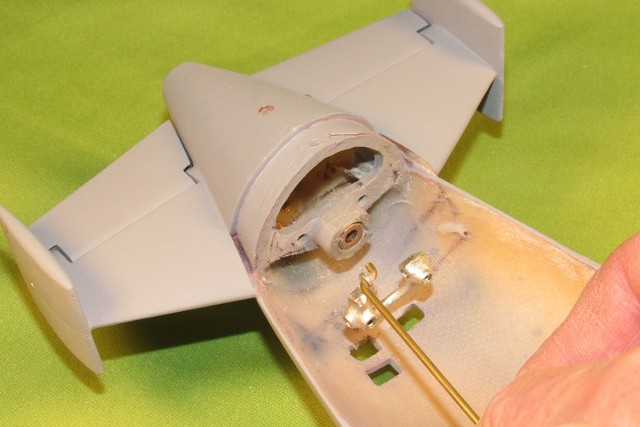
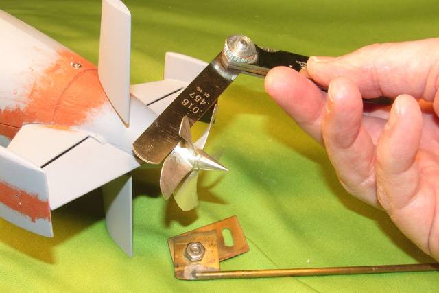
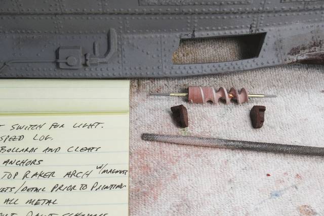
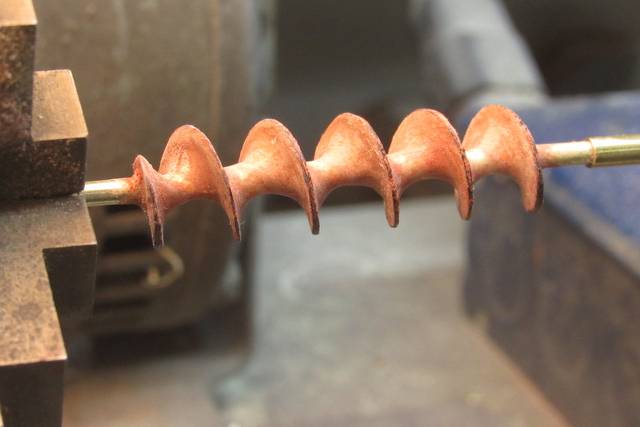
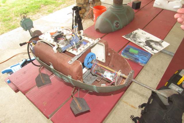
The half-way completed turbine seen below. Beneath the screw, at either end are the kit provided bearing foundations which suspend the screw within the trapezoidal opening within the NAUTILUS forward keel.
Jake, like me, makes it a shop practice to keep lists and notes of what has to be done, problems encountered, and consumables that have to be gathered to see the project through. You see some of his scratchings to the left.
Model building, particularly scale model building, is an exacting, structured activity, supported by the Craftsman's ability to engage in problem solving and mastery of techniques of manufacture.
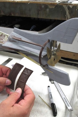
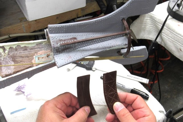
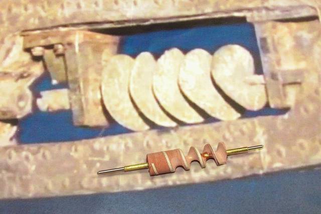
Sitting atop a photograph -- taken by the kit producer, Ray Mason, of the actual 'hero' effects miniature during its display at one of the Disneyland parks way back in the day – is the half-way completed helical screw piece Jake and I made to replace the missing kit part.
I can't help but note what an impractical arrangement this is – putting this cork-screw turbine behind all those flow restricting items: the keel itself, and the forward and after bearing foundation.
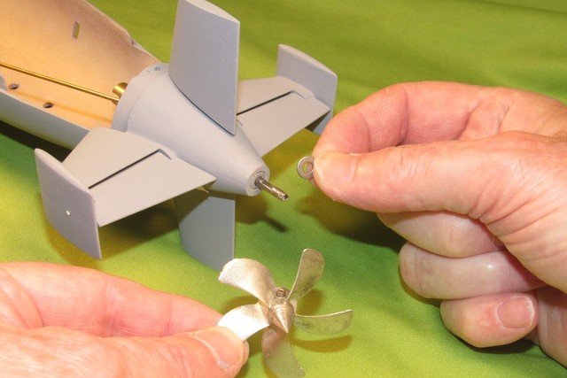
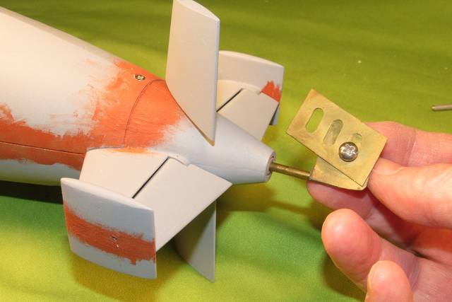
Obviously, to be a practical spinning item, the turbine was linked to a gear reduced motor within the eleven-foot long miniature to give the illusion of a working helical speed log. You can make out the drive coupler to the left, missing is the connecting shaft between turbine and hull. The detail the Disney model-builders invested on this thing is simply amazing!
The half-completed Archimedes screw sits atop the picture of the hero miniature NAUTILUS.
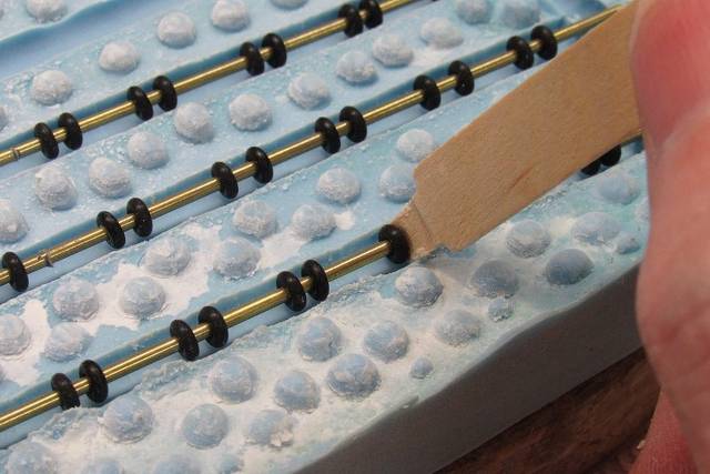
Note that the process of manufacture starts with a spiral-wrapping of a narrow piece of masking tape around a turned RenShape cylinder. The diameter of the cylinder equates to the diameter of the eventual screw. The spacing between the screws 'blades' represents the pitch of the screw. A hole down its center into which a length of brass tube was CA'ed in place. To further strengthen the structure against the forces that would be applied during screw cutting, a temporary length of steel rod was inserted in the hollow brass tube. The brass-steel core was secured at one end into a four-jaw chuck, the other end supported by the lathes tail-stock chuck – this permitted easy rotation BY HAND of the work as the material between the blades was ground away with a round-file.
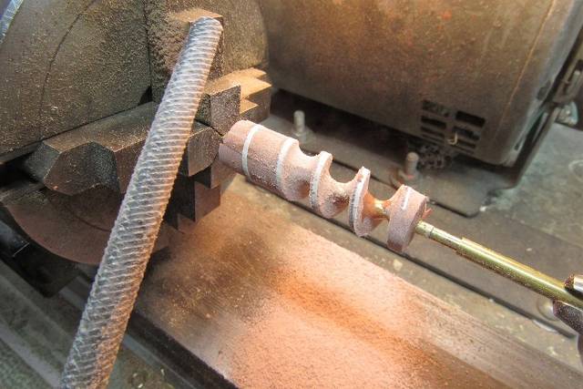
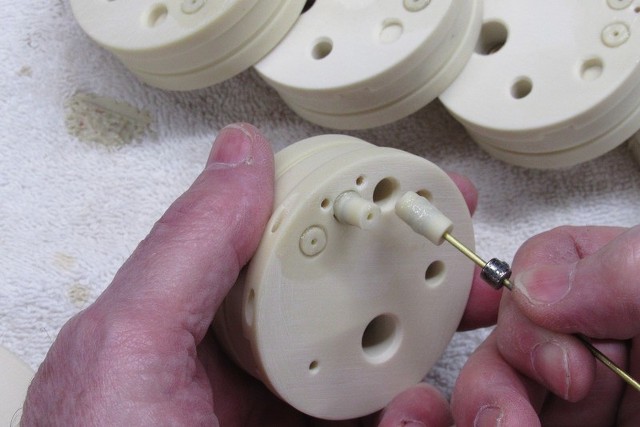
With the initial cut completed the spiral-wound length of narrow masking tape was removed – revealing a rather wide edge of the helical 'blades'.

Blackening the tips of the 'blades' with a Sharpie pen guided Jake as he cut one side of the helix with the round file to bring the entire screw to a sharp edged configuration. By this point Jake was getting pretty good at this, so the work went surprisingly quick. The boys a quick study!

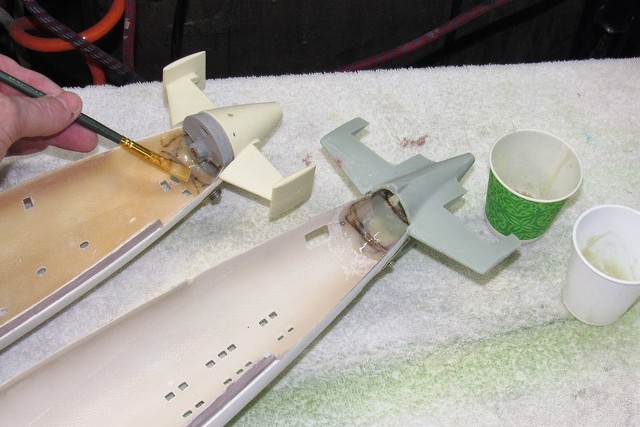
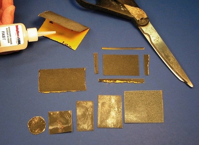
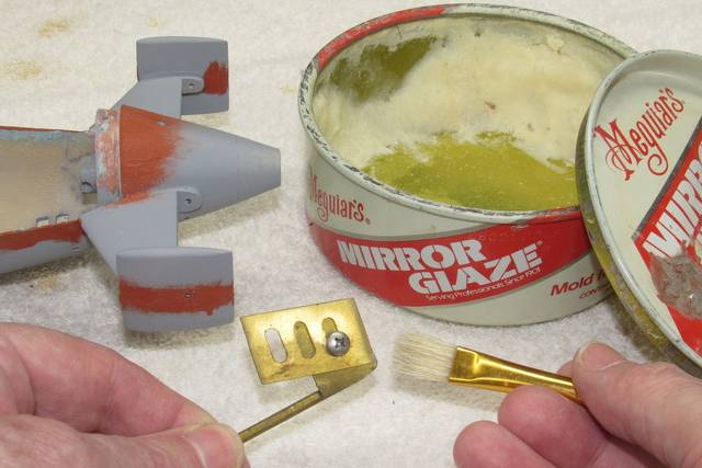
Forty-pound-per-cubic-foot RenShape is pretty stout stuff, but when cut to such thin section – particularly at the tip of the 'blades' – the stuff has little resistance to shear forces. So, after getting the helix to shape, Jake slathered on thin formula CA, quickly wiping the excess off with paper towels as he went. The adhesive quickly filled the microscopic open cells of the medium and greatly strengthened the entire structure. The fixtures ability to rotate BY HAND permitted even distribution and wiping of the work which negated any possibility of CA pooling where we didn't want it.

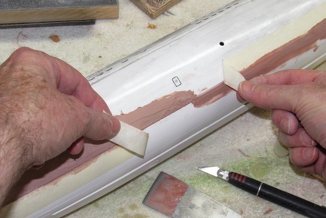
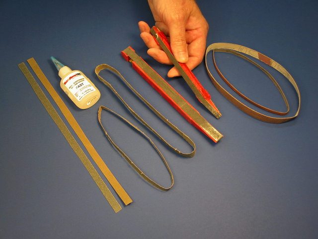
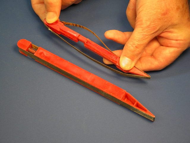
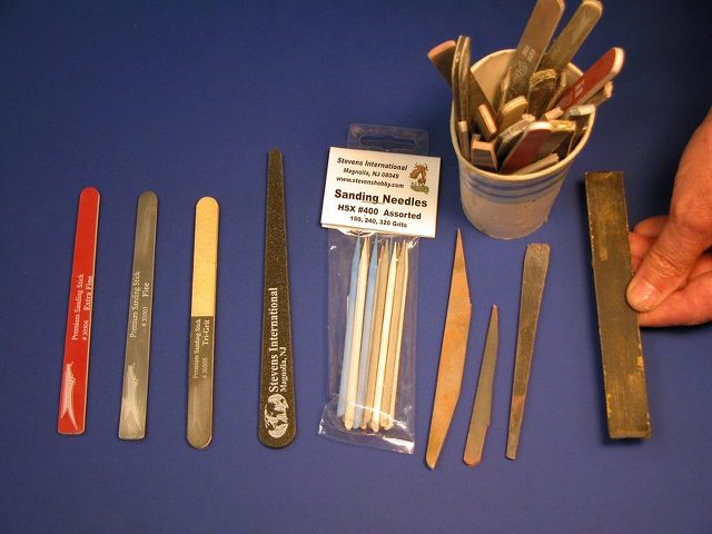
The cured CA not only permeated the cell structure of the substrate, it also left a nice – though bumpy – glaze on the parts surface. The rough surface was smoothed out using 'twists' of varying grades of sandpaper. Useful tools when working fillets and semi-round surfaces like that of this Archimedes screw.
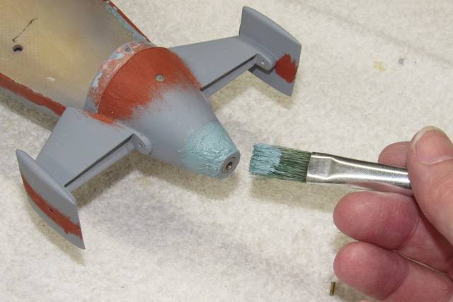
Good old air-dry Nitro-Stan touch-up putty was brushed on and later sanded smooth.
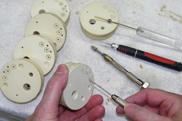
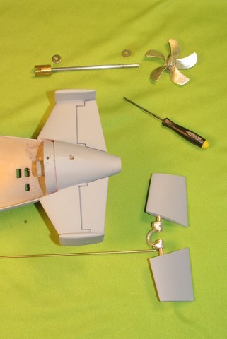
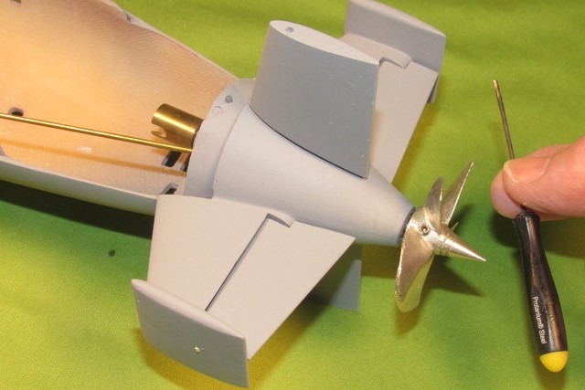
The completed Archimedes screw. After removing it from the lathe/holding fixture I left it to Jake the job of cutting the screw to correct length and mounting it within the open well of the NAUTILUS keel.
- Joined
- 18 March 2013
- Messages
- 978
- Reaction score
- 2,857
SUBEX 23 REGATTA REPORT
At my age I've trimmed down the number of major model boat regattas I attend. It's now down to three per year: The SUBEX event, chronicled in some detail here, is an all submarine dedicated weekend of submarine running, mixed in with a smattering of surface craft (AKA, targets), held at the Groton submarine base, in Groton Connecticut.
Ken Druze put together an excellent video of a past SUBEX event:
Here's a quick look at the other two regattas I attend:
SubFest A three-day all submarine regatta held in July (but open to those wishing to risk surface craft in such shark infested waters). Held at the Red Clay Resort swimming basin in Cohutta, Georgia.
The below shot, taken last year, is of my 1/60 ALBACORE model slinking around in the crystal clear swimming pool. This clearly illustrates the visibility of the water at this site. Unrestricted visibility all the way from the shallows to the deep end. Exceptional!

SubFest, hosted by The Nautilus Drydocks, organized and helmed by the world famous r/c submariner, Bob Martin. SubFest features fun-runs as well as structured events such as a course run; speed run; and judging and awards for craftsmanship, conning skills, and innovation. And for those who are nigh-owls, two nights of fun-runs.
The resort has all the facilities you need: camp-ground, grill, bathrooms, pavilions outfitted with broad work-tables where the models are staged and worked on as required, and plenty of parking only feet from the tables.
A beautiful place to run boats! For me, it's well worth the twelve-hour drive!
Located in the north-west portion of Georgia the SubFest regatta is ideal for those driving in from the east and mid-west. I've made two of these events and simply must attend these functions in the future.
Here's an informative video of the 2022 SubFest event:


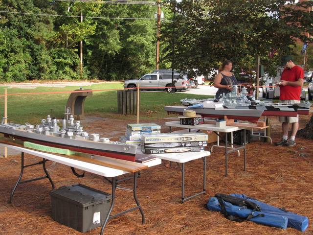
1/96 Fleet-Run A weekend model ship and submarine regatta open only to models of 1/96 or 1/100 scale. Electric or sail only. No gas, nitro, or hydro racers. Sponsored by the N.C. Model Ship Builders club, the event is held at City Lake, Rocky Mount, NC. A feature of this event is the never ending parade of like-scale warships, often conducting coordinated fleet maneuvers – a most impressive sight!
It's a bring-your-own table sort of affair, and personal tents are also a good idea if you can't find a tree shaded spot near the waters edge. Parking is plentiful and immediately adjacent to the waters edge.
Geographically the event is pretty much an east-coast sort of affair, and I like it as the event is only a two-hour drive from my home in Virginia Beach. As I'm usually the only guy running submarines at this event I have a free hand to lone-wolf it and in so doing making life miserable for the other Captain's trying to maintain fleet order as a pesky periscope tears in and out of a battle-groups carefully rehearsed formation. To most of them its all about the majesty of coordinated turns and other regimented group maneuvers. To sneaky guys like me... it's a turkey shoot!
City Lake is very well maintained and a paved walkway running the circumference of the lake permits easy and enjoyable circumnavigation of the lake.
Here's some fleet-run video:

SUBEX 23 The first r/c submarine regatta of the season for me.
Attendance was preceded by many hours of preparation – getting five submarine models checked out, repaired, adjusted, and organizing a complete field kit. SUBEX is a two-day all submarine regatta (but surface craft do participate, providing target services) held at the submarine base, Groton Connecticut.
A long tradition to this annual r/c submarine regatta. It all started back in the early 90's, the first full fledged annual r/c submarine regattas in America – a tradition that came to a grinding halt after the 9-11 terror attacks. However two dedicated guys, Ray Mason and Joe Oliver, working with the base authorities, have re-established the regatta and we're back running our submarines at North Lake. Just like old times, but with far fewer participants. But the numbers grow with each new year.

Preparation is everything in this game of r/c model submarining. Only r/c helicopters – because of their complexity – demand this kind of attention from the participant. Real helicopters have close to a 1:4 fly/maintenance ratio!
I worked it out once: on average for each hour of in-water operation a model submarine will undergo two-hours of post and pre-mission checks.
To operate consistently, long-term, the r/c submarine must undergo stringent checks and procedures: pre-mission – getting the hull and WTC out of storage, integrating them, and get the system into working order; mission – those tasks at the lake or pool required to keep the submarine in working order; and post-mission – those tasks performed when the model is back home where the problems encountered at the lake are addressed, after which the hull and WTC are put into a state of preservation and stowed in a safe place.
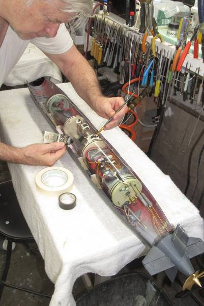
Post-mission operations are personified by this shot. Here I'm replacing a bum servo within my 1/60 ALBACORE WTC/SubDriver – a problem that occurred during a previous run, recorded on paper so I wouldn't forget, and that task added to the other chores performed back home during the post-mission phase. Note the 'to do' list lower-right.
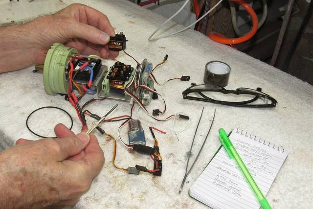
Under the North Lake pavilion you see my work station, adjacent the base golf course. Tools and consumable at hand and ready for use. Mission checks and operations quickly become a pain if you have to dig to the bottom of a tool chest to get the things you need, it's best to have your gear set up and ready for surgery if (and when) the time comes for on-site adjustment or repair. A place for everything, and everything in its place!
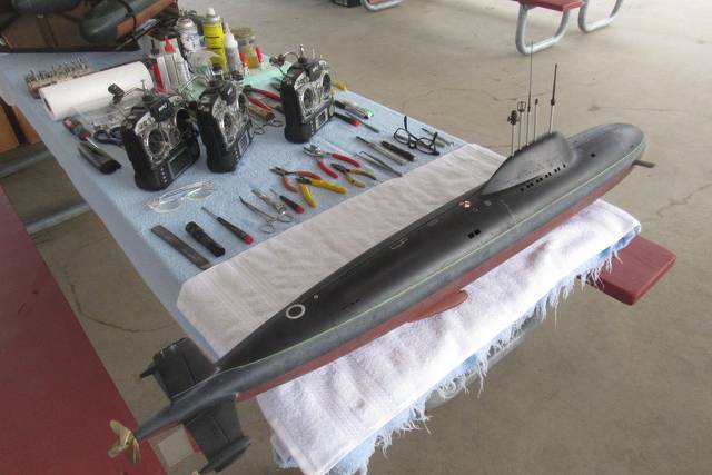
(Today I have about twenty-five fully operational r/c model submarines. Different subjects, different scales, and various sizes. The smaller models are reserved for restricted bodies of water, such as pools and medium sized ponds. The larger models are for lakes, large ponds, and coves).
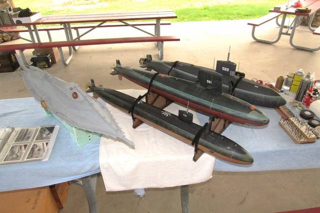
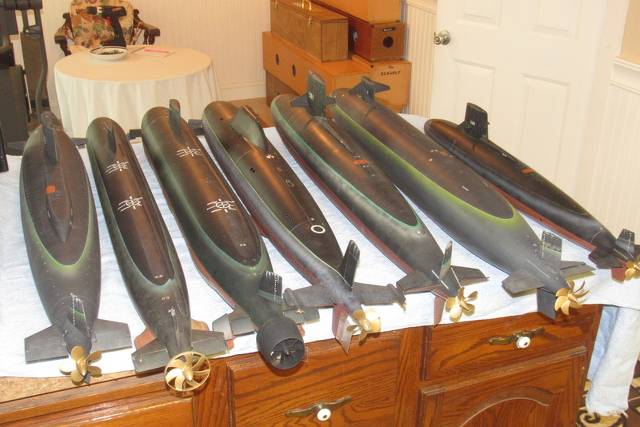
For the Groton run this year I selected two of the longer 1/96 boats, the flight-2 LA class, and the SEAWOLF; the 1/72 SKIPJACK and 1/72 ALFA (not pictured here); and the trusty 1/60 phase-2 ALBACORE. All big enough to have 'presence' on and under the water, but not big enough to hurt this old mans back.
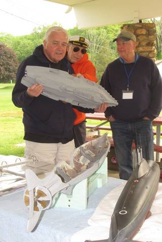
At some events table space is at a premium (not so at the Groton events – today number of participants is much smaller than in the good old days before 9-11), so I built this 'stacked' boat display stand to hold and display the boats not in immediate service. Velcro straps holds each model securely upon the stand.

I have an identical stand, sized to hold smaller diameter boats.
To the left you see an almost completed Disney NAUTILUS, still in primer gray. Assembled from a kit Ray Mason produced over thirty year ago by David Jacobs 'Jake' is a big-time r/c model tank buff and should be done with his NAUTILUS and have it running in time for the big SubFest regatta coming up this July.
In my capacity as 'teacher' I've started to bring along binders to these events containing pictures of our work over the decades. Rich in illustrations dealing with scratch-building, vacuforming, acid-etching, glass lay-up, painting, master making, tool making, masking, weathering, WTC's, etc.
The only way we're going to keep this hobby of ours alive is to pass on our 'institutional knowledge' to the youngsters. Publish or perish, so the saying goes among the learned.

There's a reason I dominate r/c submarine regattas here in the States: I come prepared. I don't come to play. I come to kick ass and take names.
I arrive with the tools and consumables to not only adjust, but to make significantly involved repairs, on site, if required. R/c model submarines belong on/under the water, not stuck sitting on a boat-stand under a pavilion roof. SUBEX 23 was typical: Out of some 25 participants, a quarter of them managed to get their model r/c submarine to work credibly underwater this year.
Clearly, a lot of guys are not doing enough maintenance at home.
Dammit!... don't bring broken toys to a toy show!

My partner in crime, Kevin Rimrodt. Here he's playing... err... studiously and exhibiting stunning professionalism, trimming out my 1/96 flight-3 LA class model. I brought five boats to Groton this year... five WORKING boats!
The two of us shared the driving chores up from Virginia. In spite of working in a three-hour buffer between the time we planned to arrive and the traditional 5PM meeting at the Groton Townhouse restaurant, Connecticut rush-hour traffic stepped in and slowed us to the point where we arrived at the eatery with only ten-minutes to spare! I simply hate that span of I-95 between New York and New London!
Saturday, the first day of the two-day event, was raining cats and dogs. However, Kevin … looking a lot like Gabby Hayes here... and I did get in some check-out drive-time between rain squalls!
However, the Saturday showers meant little to most of the attendees as the majority of them had signed onto a tour aboard a VIRGINIA class submarine tied up at the waterfront. (Meanwhile, with tables left unattended, Kevin and I got to rummaging through unattended coolers and lunch pails).
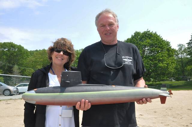
One of the two spark-plugs of SUBEX events – the guys who coordinate with the base for the use of the North Lake – is Joe Oliver. Here, with his wife, 'Jimmie'. We are all indebted to Joe and Ray Mason for all the hours of work required to make things run smoothly at this very security strict regatta site.
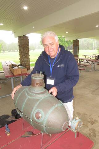
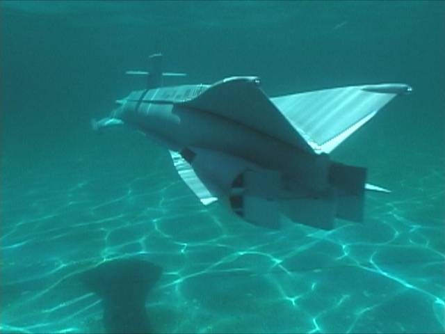
That neat looking hydrofoil has been a long-term project of Joe's and he's finally just about got it dialed in. Based on a 32nd Parallel kit, this speed-demon has been decked out as some kind of Nazi marine vunderveapon. Nice.

The other 'wheel' that makes the SUBEX events reality is Ray Mason. This guy was there at the beginning of the SubCommittee sponsored North Lake regattas back in the early 90's. He and Joe put the ball in play again at the base after the 9-11 shut-down. The reason we all now have access to the submarine base North Lake is because of the hard (and sometimes frustrating) work of Joe Oliver and Ray Mason.
Ray is a fantastic model-builder. SEAVIEW, SWORD, the Disney NAUTILUS, are all scratch-built models created by him – and he did that work decades ago.
Ray's the first guy in America to operate a credible looking and handling SEAVIEW – in fact that same model, now in the capable hands of Frank Salerno has undergone an extensive expansion and was on-site this year and actually made it into the water for its initial post-yard period sea trials.
And know that most the pictures here were taken by Ray and used with his kind permission.
Frank Ricucci standing behind some of his outstanding model work. From the left is a gray German E-Boat of rather large scale; next is a 1/24 Anfora kit of the Spanish steam-powered ICTINEO ll; and to the right is what appears to be a 1/6 scale Cottage Industry Models, TURTLE. Frank's not only a skilled kit assembler, he's also one heck of a practical engineer. His work is so crisp!
Ask Frank how one finger-checks a stamping machine (but do work out a quick escape plan before asking that question).


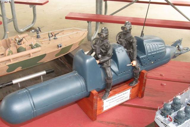
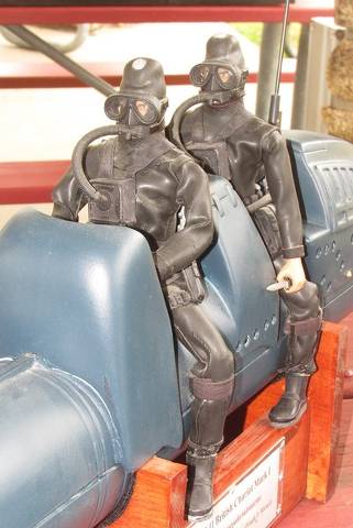
Frank fashioned the Diver suits from rubber gloves. Simply perfect!
(if I was the guy driving I would beforehand made sure the guy in back knew I owed him money... look at his eyes!)
Ken Druze and his first-mate, Carol, showing off his very well trimmed out and running Moebius Models 1/72 SKIPJACK. Ken also brought along his SubTech 1/35 MARLIN, another well running model submarine that kept everyone watching entertained Sunday.
An exceptional scratch-builder, Ken's favored subjects being party/charter boats, subjects he lavishes with obvious and hidden detailing that screams 'museum quality' to even the most casual observer. However, it seems that whenever this guy and me have a boat in the water at the same time things can't help but turn into a knife-fight! We do swap paint on occasion.
Jerry Pavano's long suffering Disney NAUTILUS. He's been bringing this beast to just about every North Lake event I can remember. Finally!... he's got the thing working in surface mode. I got him to promise that next year the boat will actually operate submerged. The guy just won't quiet.

- Joined
- 18 March 2013
- Messages
- 978
- Reaction score
- 2,857
PART-2
After years of work, Frank Salerno got his big SEAVIEW into the water for some surface running. What a sight! Beautiful. Originally built by Ray Mason. After Frank took custody of the model he lengthened the hull, gutted the interior and turned the insides into a Plumbers nightmare... and I mean that in the nicest sense; the thing now has bells-and-whistles on top of bells-and-whistles. For example, for servicing the interior the superstructure is lifted clear of the hull through two internal pneumatic jacks. Well, that alone was enough for me!... Frank is definitely Certifiable.
North lake has a sandy bottom, and that sand extends well onto the surrounding property. That sand presents a hazard should a wet-hull type model submarine ground as the sand will get inside and could tear up pushrod and shaft bearings as well as get into the tight spaces between the leading edge of control surfaces and trailing edge of supporting stabilizers, effectively rendering them inoperable.

Frank worked as an industrial model-maker at the Grumman company, and his expertise gained from that experience is showcased in everything he puts together. He's a practical mechanic if I ever met one.

]
The surface runs revealed poor propulsion efficiency. I suggested to Frank to not rely solely on the scale 'shark gill' intakes, and to open up huge auxiliary inlets into the bottoms of the propulsion tubes, ahead of the gills. We'll see if that helps come next years SUBEX.


Sunday was clear and turned into a perfect day.
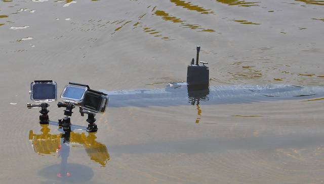
Fred Freketic. Long time r/c submarine nut, customer, and friend. Here operating his 1/72 THRESHER. This guy is a first-class photographer, both video and still. When not driving toy submarines he can be found airborne in a WW-2 era bomber taking fantastic video. If you're into that sort of thing you likely saw some of Fred's work on YouTube and other outlets.

When it comes to documenting the activity, Fred does not fool around. Here is a rather exotic looking camera mount supporting no less than three go-pro type video cameras. The boat passing by is Ken's MARLIN.
North Lake is basically a fresh water holding pond that has been turned into a base swimming hole for members of the military through the addition of a Chlorine pump-house with a filtration system; bathroom and changing facilities; lawn furniture; and atop a sizable bluff, a long roofed pavilion to provide shade or shelter, depending on the weather; and within the pavilion, pick-nick tables, overhead lighting, and electrical outlets.
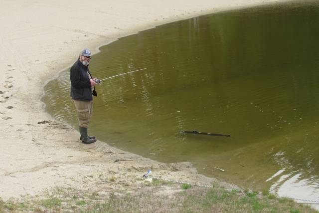
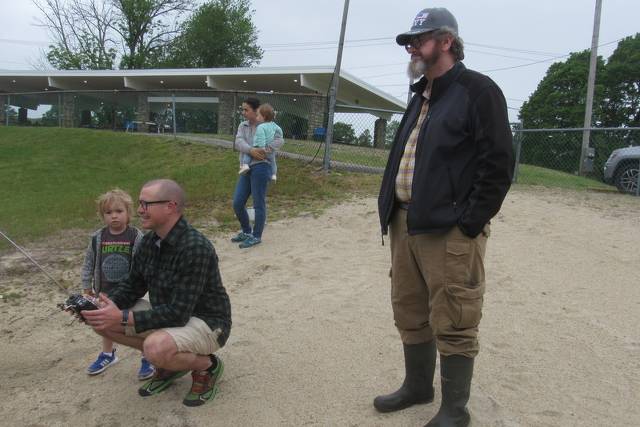
But, I want to emphasize that this photo shows more than just a body of water, it paints for us what I hope will be the future: A father and wife with their children discovering this hobby – locals who heard about the event and drove over to see what it was all about.
Kevin has given Dad the transmitter and in only a few moments of indoctrination the man is running the boat submerged and obviously enjoying the experience.
Yes! We got our hook into this one.
Here, Brian Wright has handed off his transmitter to an interested sailor. They are atop the bluff overlooking the lake. A great vantage point from which to drive r/c watercraft.
To the future belongs the young and young of heart. And may that future contain people who still creatively use their hands and minds.
(If we can only get the corrosive phones and 'game-boys' out of their hands and brains).

Our drive back to Virginia was uneventful and almost pleasant. Dropping Kevin off at his digs I continued south another fifty-miles, pulled up my drive and proceeded to stage the boxed models through the shop and into the dining area. Thus began the long, and somewhat tedious post-mission tasks.
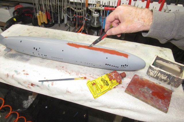
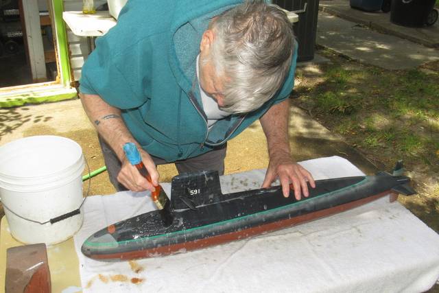
The models were unboxed and the WTC's pulled and set aside on one of the shop benches. The model hulls had collected North Lake sand through their bottom flood-drain holes, and dried duck poop and water-spots clashed with my paint and weathering. I addressed the hulls first.
Dunking a hull into the outside 'test-tank' filled it with water. Before all the water could drain back out I tipped and rocked the hull back in forth. This worked to dislodge internal sand and muck which drained back into the test tank. About three cycles and the interior was clean enough.

Each hull got the once-over with a soapy water filled soft paint-brush. I took care to use a mild detergent so as not to bleach out the paint, clear coat or any touch-up acrylic paint applied to hid collision and handling dings collected over the years.
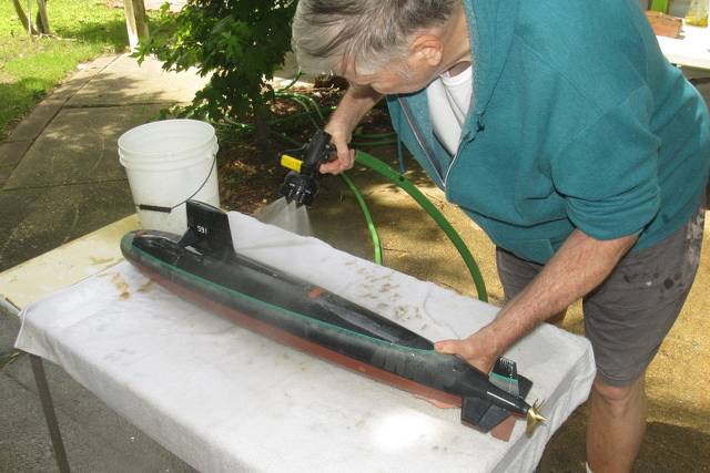
The soapy scrub was followed by a thorough rinsing with the garden hose. At which point the hull was marched back into the shop and toweled down. From there it went back into the dining room where it was left to dry overnight.
The water tight cylinders get the most post-mission attention as they are the heart, brains, and brawn of an r/c model submarine. All of my submarines are of the 'wet hull' type, i.e., the hull proper is not a watertight structure. In fact the hull serves only as an attractive streamlined vessel containing the WTC and supporting the control surfaces and propulsor. The WTC is divided into three spaces by four bulkheads. The forward dry space contains the battery, the center compartment functions as a ballasts tank, and the after dry compartment houses the control and propulsion devices.
As the hulls dried out in the dining room I started my inspection and testing of the WTC's by turning each on and driving its functions with the appropriate transmitter. Any servo chatter or out of specifications response was noted and addressed.

Though I encountered no obvious water intrusion into any of the WTC, is remained a MANDITORY requirement to stow each WTC with the forward and after bulkheads unseated to insure that any moisture in the form of hard to detect condensation will have the opportunity to evaporate away during storage.
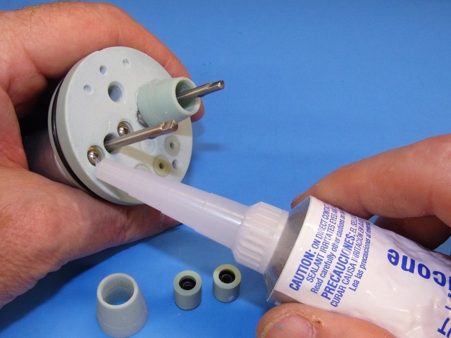
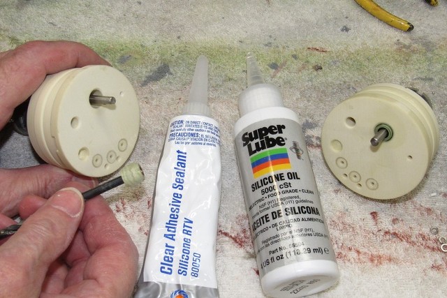
Here I'm oiling up the inboard side of the servo pushrod seals as well as the propulsor shaft with silicon oil.

Long ago I switched to Lithium-polymer batteries for propulsion and hotel services aboard the WTC's. The exceptionally high power density (more Amperes per unit of weight) of these sometimes temperamental chemical hand-grenades makes them a near perfect source of energy within the tight confines of an r/c model submarine.
Here I'm checking end-of-mission voltages, and charging the batteries after my arrival back home from the Groton SUBEX 23 event. Once they're all banged up they are placed in safe storage... OUSIDE OF MY HOUSE!!!!
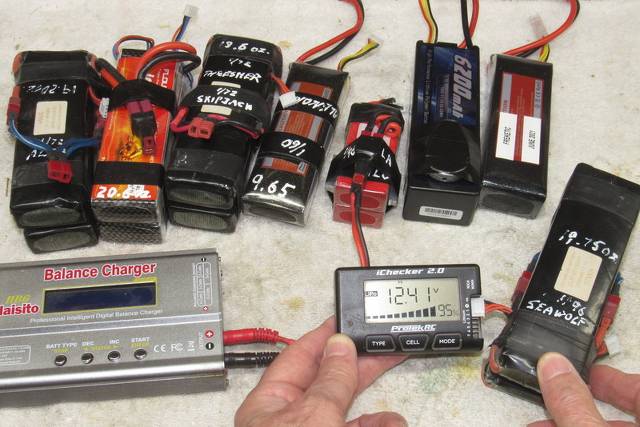
The charged batteries are placed into a water-proof ammo-box and placed outside. Note the white duct tape. I've pulled it away to reveal a hole I punched into the side of the ammo box. That hole and tape is a 'blow-out plug' used to vent the box if a battery fire erupts (and these little fuckers WILL burst into flames sometimes!), the holes function is to vent the box, preventing it from exploding do to a sudden internal over-pressure should things get nasty within. It won't save the batteries, and the box will become a molten pool of goo, but it will serve to keep shrapnel out of my neighbors fanny and prevent my house from burning down.
Ah... chemistry! Got to love it.

And this, boy's and girl's, is how you insure safe storage of Lithium-polymer batteries: outside the house, on a cement slab. In watertight, explosion proof boxes. Well distanced from the house.

Post-missions completed, each hull is placed into its shipping-stowage box, awaiting the next regatta.
If done right, r/c model submarining is not a 'casual' activity. It requires planning, adherence to established procedures, and your full, undivided attention. The reward for all this? A fun, successful day at the lake or pool.
Works for me.
- Joined
- 18 March 2013
- Messages
- 978
- Reaction score
- 2,857
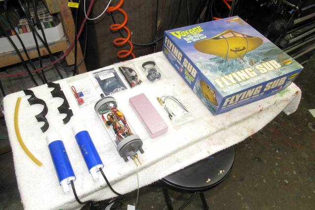
new toy!!!!!!
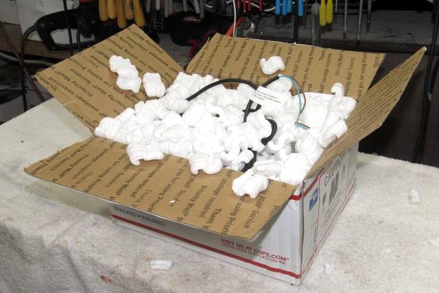
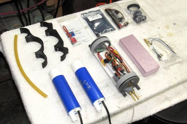
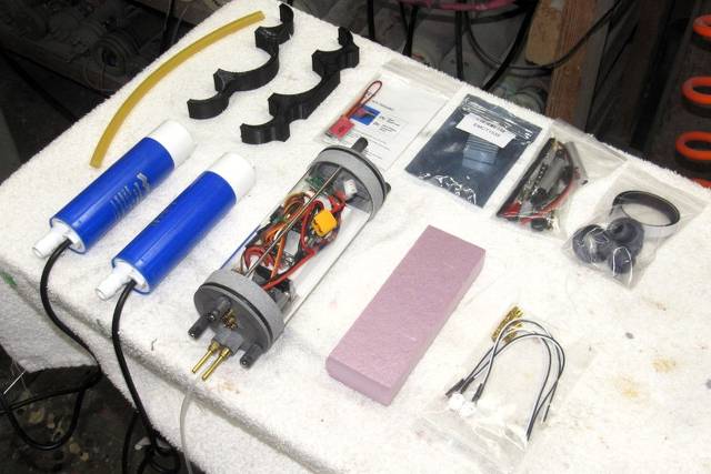
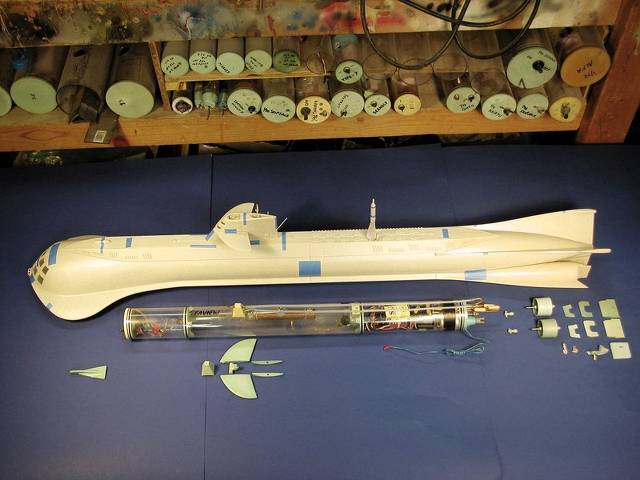
Just arrive about twenty-minutes ago. The Nautilus Drydocks FLYING SUBMARINE conversion kit!
Like I don't have enough unfinished projects on my shop tables and hanging off the wall?!....
Damn you, Nautilus Drydocks!
Already my mind is in over-drive thinking about the addition of pump-diverters to enhance yaw rate; differential nozzle control to achieve banking turns (no more healing out of the turn), and other Bizarro stuff too horrible to announce in a public forum.
To be continued...
David
Squealing with Glee like a little girl on a Pony
- Joined
- 18 March 2013
- Messages
- 978
- Reaction score
- 2,857
REPAIRING A LEAKING MOTOR-BULKHEAD
But first, a little background.
Many moons ago Gary Kerr, who worked as lead-man on several Moebius Models kits, designed the definitive SEAVIEW model kit. That effort first centered around the 'TV version' of the submarine; a later release was of the 'movie' version.
Though these injection formed polystyrene plastic kits are intended for static display only, I and others have converted them for r/c operation.

The Caswell company, during a ten year span, employed D&E Miniatures (our business) to head development and production of items for the r/c submarine market. One such effort was a SubDriver (proprietary name given to a removable water tight cylinder) and 'fittings kit', to convert the Moebius plastic model kit into a practical, well running r/c model submarine.
The SEAVIEW SubDriver (SD) – unique in that it featured an exceptionally large ballast tank – had to float the surfaced fictional submarine at a ridiculously high freeboard; and housed two motors to drive pump-jets fixed within the propulsion tubes at the models stern.
In support of the SD and fittings kits we authored articles and videos which described how to convert the Moebius kit, through the incorporation of our products as well as how to gain easy access to the hulls interior by making the superstructure removable.
The SD was suitable for both the TV and movie versions of the SEAVIEW. However, as there are significant differences between the bow and sail of the two versions of this science fiction submarine, we were compelled to produce two versions of the fittings kit.
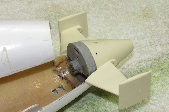
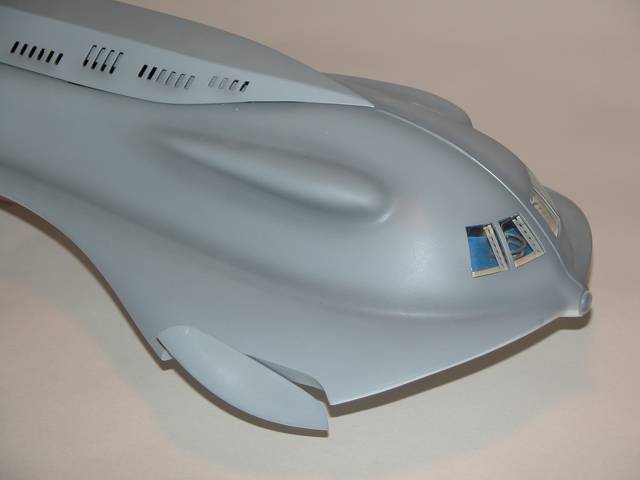
Demonstrating this: the picture below shows the movie SEAVIEW SD and fittings kit. This fittings kit has no provision to make the bow planes practical. On the other hand, the movie version fittings kit contained conversion parts to make the bow planes practical. (you can see what an ugly arrangement practical bow planes were below, and the two pictures that conclude this article).
Practical bow planes on this submarine look terrible and were found to be of limited utility in the water. As these control surfaces were so tightly nested into the tips of the SEAVIEW's strakes they become subject to turbulence that blanketed them from rational water flow, reducing those control surfaces effectiveness. And once they deflect in operation... THEY LOOK AWFUL!

We placed an emphasis on providing functional control surfaces, and efficient pump-jet propulsors – and to render those items to scale with the SEAVIEW; no over-sized control surfaces or out-of-place running gear. The last thing we wanted to do was corrupt Gary Kerr's excellent work of capturing the 'look' of Admiral Nelson's iconic submarine.
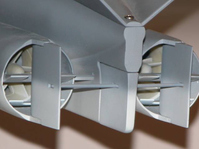
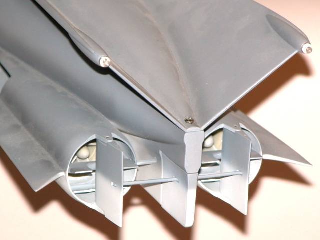
However, and these were necessities of function, departures from scale included opening up the pump-jet intakes in the propulsion tubes ahead of the internally mounted pump-jets; punching flood-drain holes either side of the central keel; and inclusion of a set of guide-vanes within the propulsion tube nozzles.
Those well hidden guide-vanes produce a pitch-up moment to the submerged submarine when thrusting ahead, needed to counter-act the pitch-down moment produced by the shovel shaped bow.


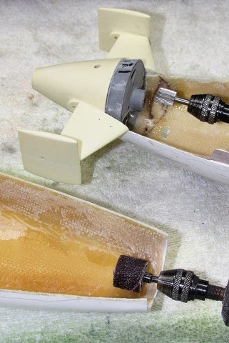
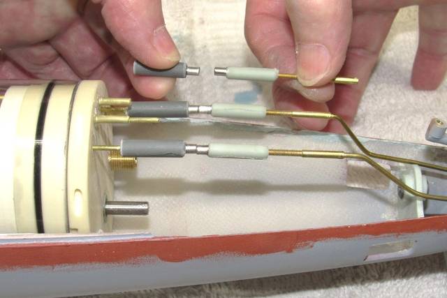
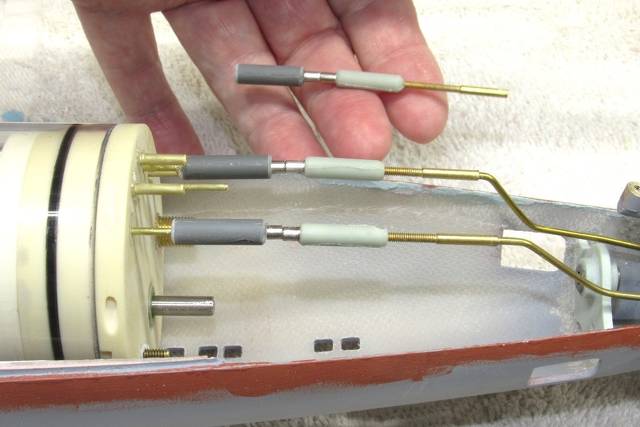
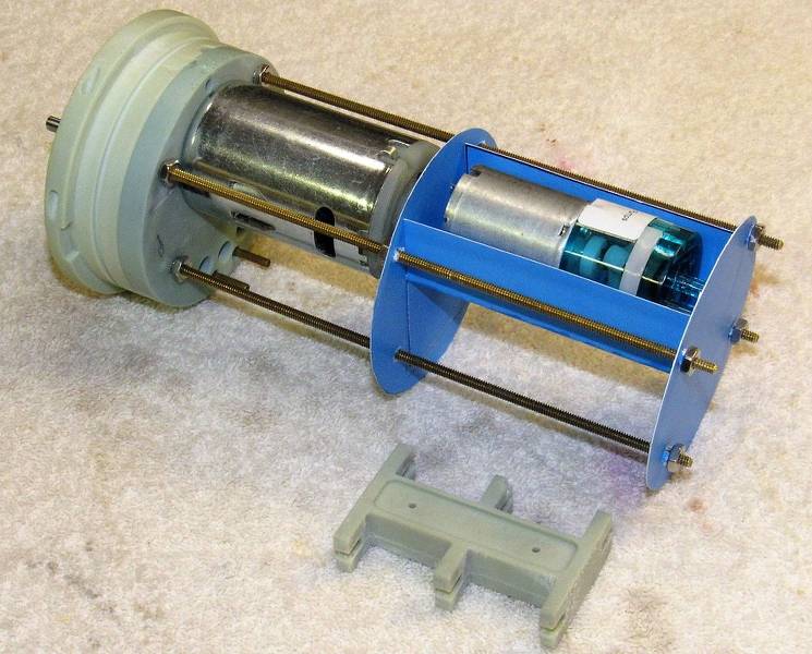
As the pump-jets are fixed within the narrow confines of the propulsion tubes, a means of easily making up the intermediate drive shafts that inter-connect the SubDriver motor shaft to the rotor-shaft of a pump-jet and are inaccessible to fat fingers. The solution took the form of spring-loaded, telescoping intermediate drive shafts.
Note that there is very little room near the stern, and the long reach the intermediate drive shafts have to make to reach the rotor shafts within the pump-jet duct.
Once seated onto the lower hull indexing pin the SD and motor coupler can not be moved to engage the 'dog bone' at the forward end of each intermediate drive shaft. The spring loaded intermediate drive shaft itself moves axially slightly to permit engagement of its dog-bone to the SD's coupler.
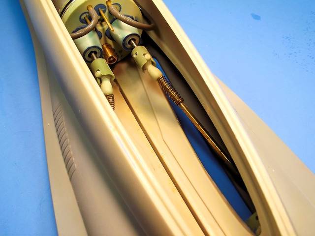
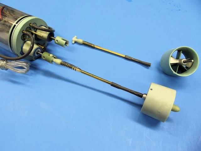
A SEAVIEW intermediate drive shaft is a unique affair, comprises two lengths of square brass tube, of varied diameter, one sliding within the other. Square to prevent rotation of one tube within the other. A compression spring, compressed against the after end of the dog-bone, its after end soldered to the after length of square tube. When the forward square tube is pushed into the after square tube – in ordere to insert its dog-bone into the motor coupler -- the spring is compressed and exerts the force needed to return the intermediate drive shaft to its correct length with the dog-bone nestled tightly within the coupler. Residual spring tension keeps the dog-bone engaged.
A length of flexible tube serves as a poor-mans universal joint between intermediate drive shaft and pump-jet rotor shaft.
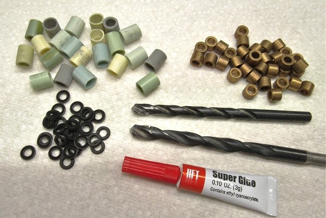
One of my boating recently observed that his SEAVIEW motor-bulkhead was leaking and would I give him a hand with it.
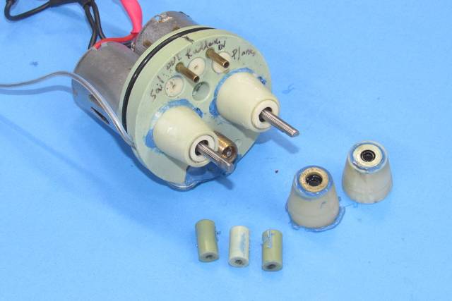
When it arrived I dunked it into the test tank and ascertained that two of the pushrod seals and one of the two motor drive shaft seals were indeed leaking. The fix was simple: replace the bad seals with new. The cause of the leaks was time, and possibly the use of hydrocarbon based lubricants (natural buna rubber degrades with that class of oil). Silicon grease/oil is recommended for those type rubber elements.
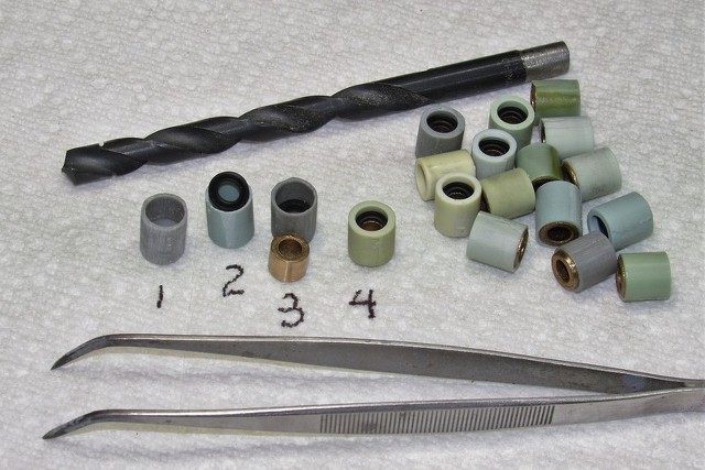
Look closely at the six pushrod seals at the bottom of the picture. The dark green ones – just liberated from the motor-bulkhead – are original, and of the single O-ring type. The tan pushrod seals vary in that they have encapsulated within two O-rings. If you look closely you can just make out the dark O-rings through the semi-transparent tan resin.
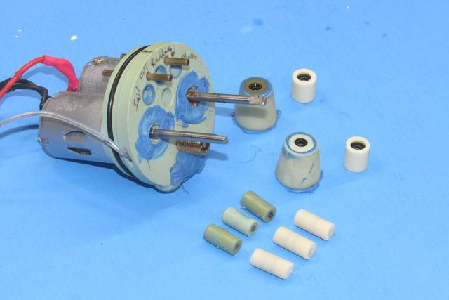
The shaft seals are proper cup type rubber seals. The original pushrod seals employ a cylindrical cast resin body within which is encapsulated a single O-ring. Now I produce those seals with two O-rings, which greatly increases their longevity.
The picture below shows pushrod seals for both 1/8” and 1/16” diameter pushrods. In cut-away you can see how the O-ring projects slightly into the bore of the seal body to effect a watertight seal between the pushrod and seal body.
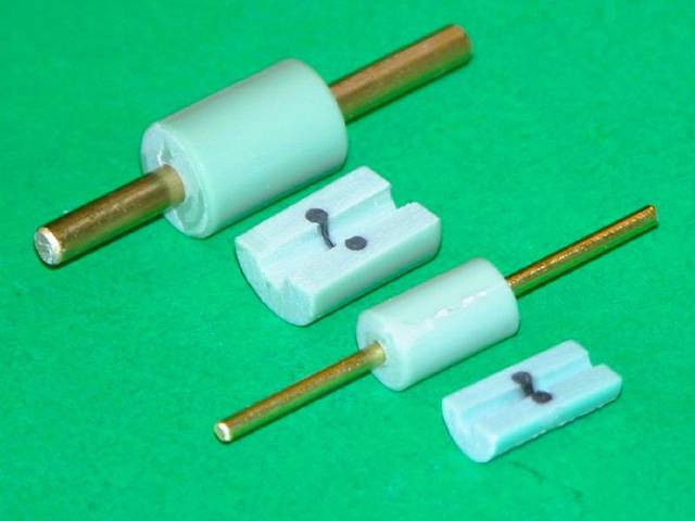
A couple of years ago, responding to complaints of leaking around our pushrod seals (I was observing the same problems with my own boats), I improved the tooling used to create these seals – increasing the number of O-rings from one to two.
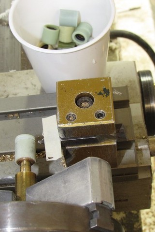
The O-rings, each girdling a central brass rod mandrel, form the sealing rubber element within the cast resin body – here I gang as many as ten seals on a single length of cast resin rod.
The brass mandrel is pull out and the individual seal bodies liberated on the band saw.
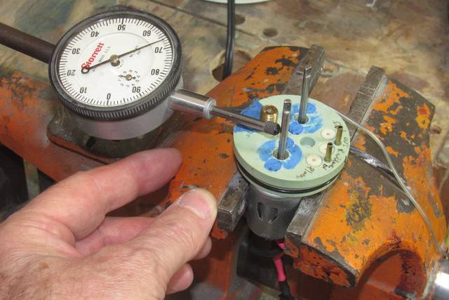
Before making up the new motor-shaft seals I ran the motors to make sure they were working fine. They were, but I found one of the shafts to be off-center. Way... way too much 'wobble'. That had to be fixed first.
Securing the motor-bulkhead in the table-vice (very softly, taking care not to crush the motor cans) I check the degree of 'wobble' of each shaft with the dial-indicator. I've gotten pretty good at bending the shaft back into near perfect alignment with a tug here and a tug there with my fingers alone.
Once things were spinning reasonable true it came time to make up the new motor seals, and get this sucker out of the shop.
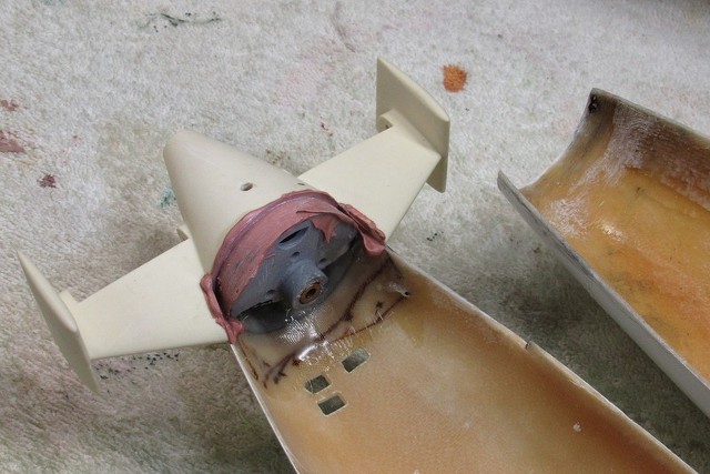
Note the three new-and-improved pushrod seals already RTV'ed within the motor-bulkheads body, sitting flush with the after face of the bulkhead.
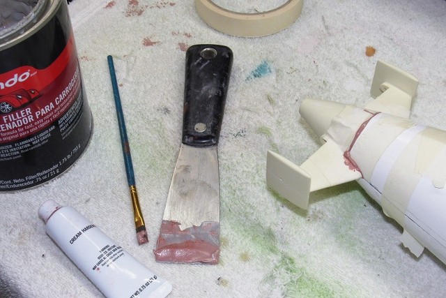
The new motor bulkheads, and their conical support foundations were RTV'ed in place and presto-change o!... … fix y-poo!
The Good, The Bad and the Ugly!
A dunking in the test tank to check for leaks. None! And off to my pal went his repaired and tested SEAVIEW SubDriver motor-bulkhead. Now, with his mighty SEAVIEW back in commission he can rejoin the task of ridding his nearby lake or pool of those nasty Aqua-men, ghosts, aliens, blazing Van Allen belts, evil world-take-over cabals, mad-scientists, and Lobster-men.
You're Welcome!


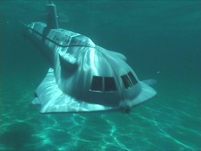
Some bonus material for you: One of my assembled Moebius SEAVIEW kits in the water, as well as video footage taken from inside the bow, looking through the 'glass' windows.
David
- Joined
- 13 August 2007
- Messages
- 7,149
- Reaction score
- 6,522
i subscribe to your YouTube cannel
that Seaview sub with inside camera is splendid
that Seaview sub with inside camera is splendid
- Joined
- 18 March 2013
- Messages
- 978
- Reaction score
- 2,857
Thank you sir. If I ever find the time, I want to build a scale looking facade to cover the clear plastic 'window' retainers we see in that footage. So much to do... so little time.i subscribe to your YouTube cannel
that Seaview sub with inside camera is splendid
David
- Joined
- 18 March 2013
- Messages
- 978
- Reaction score
- 2,857
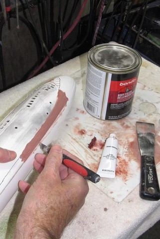
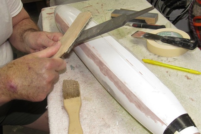
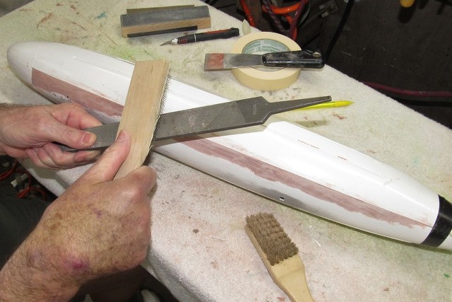
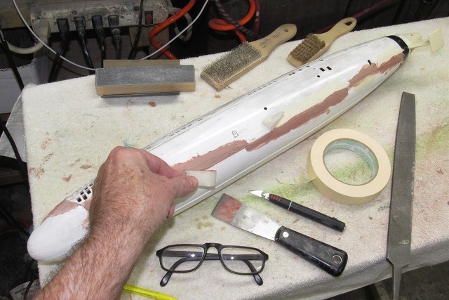
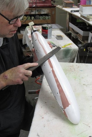
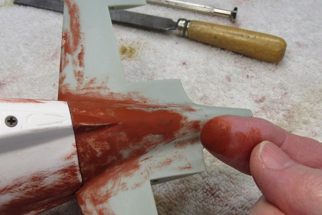
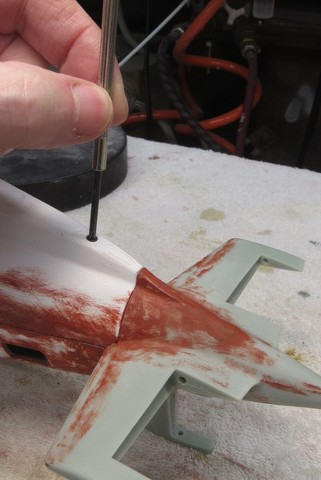
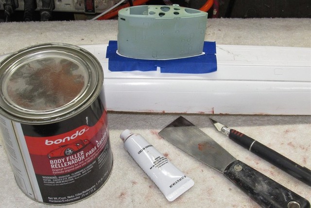
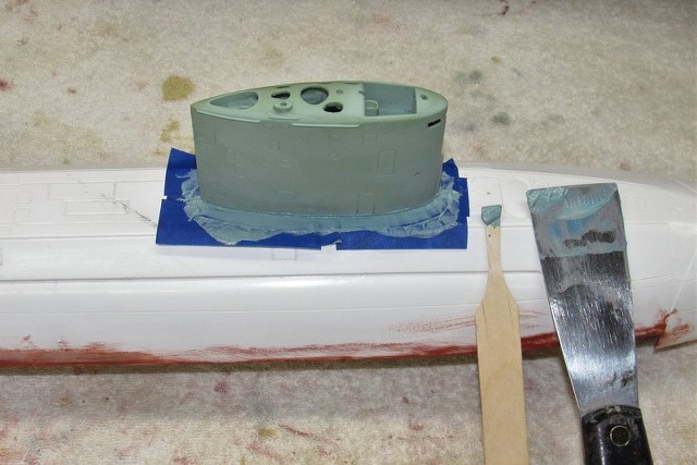
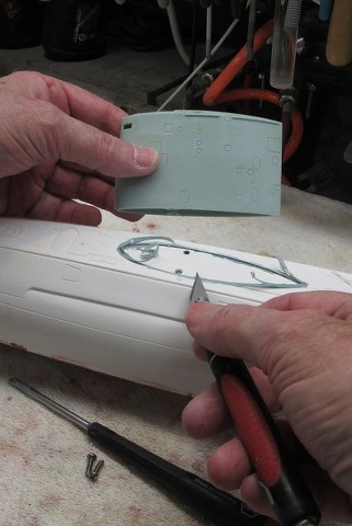
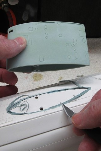
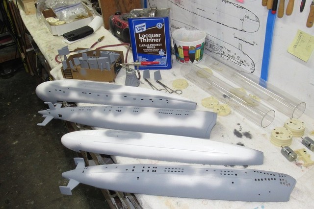
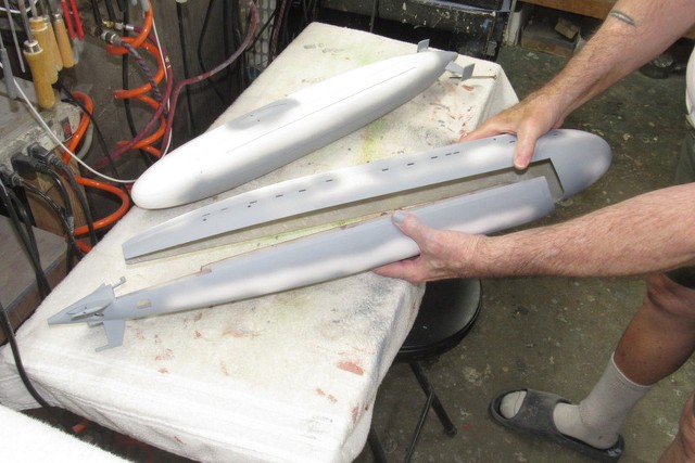
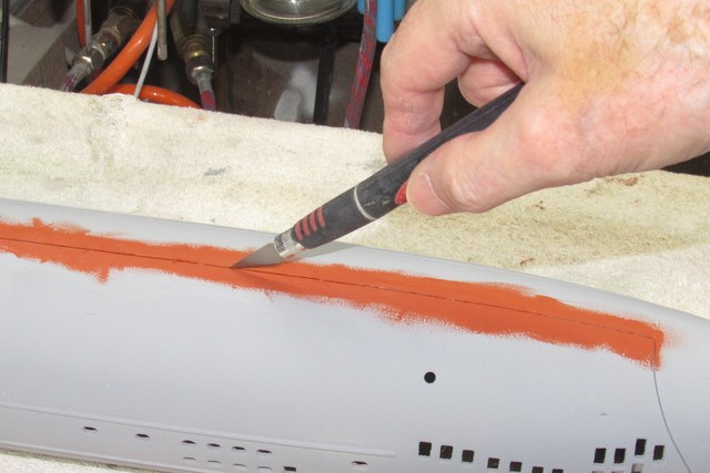
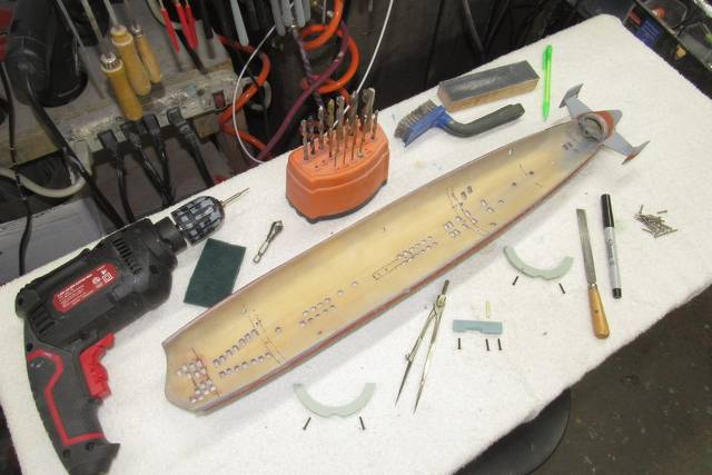
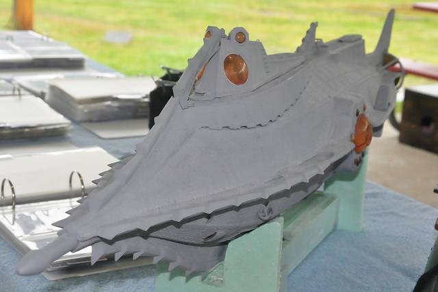
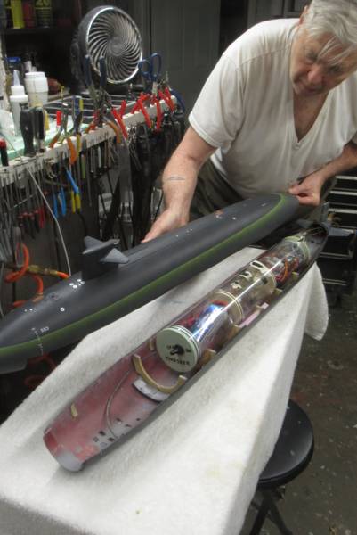
David Jakobs (Jake) is all but done with the assembly of one of those very rare and beautiful Ray Mason Disney NAUTILUS'. Here it is in primer gray. This weekend we trim it out in my test tank and get it operational, then finally a proper paintjob. But first... a few missing details.
.


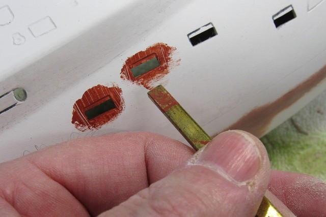
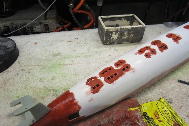
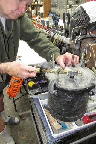
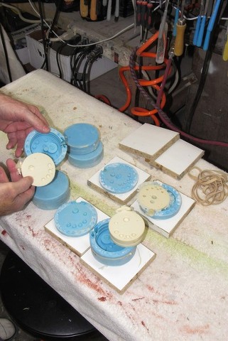
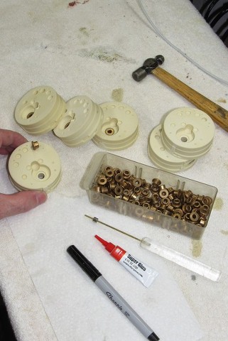
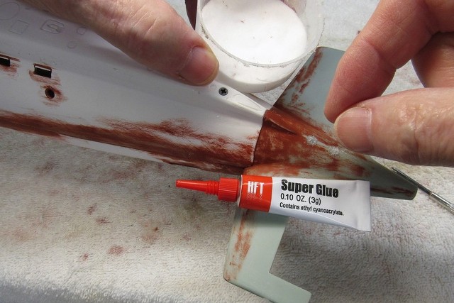
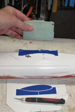
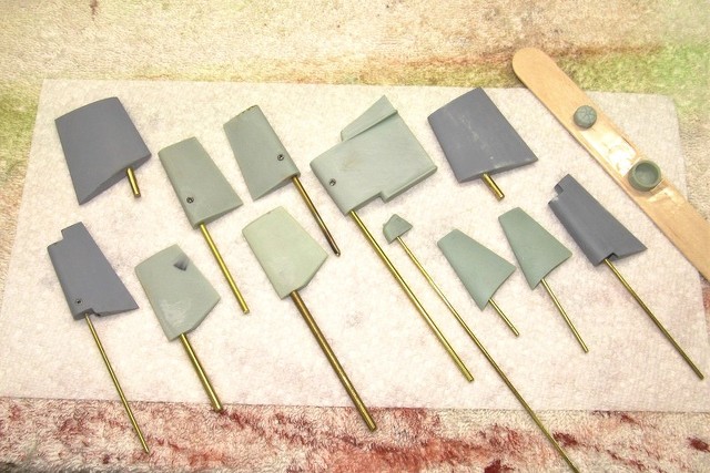
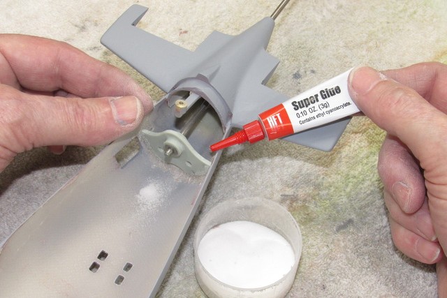
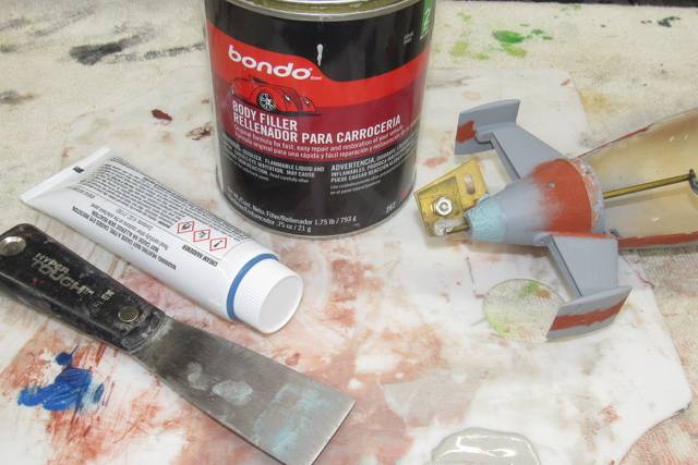
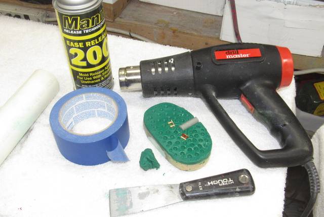
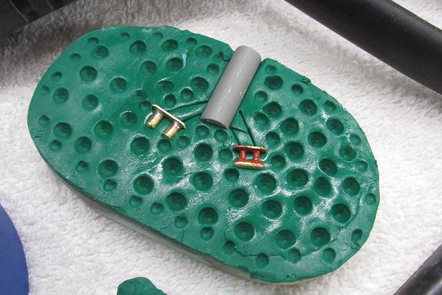
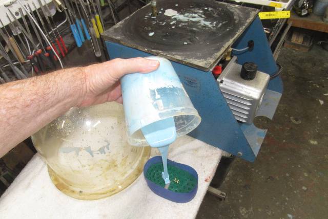
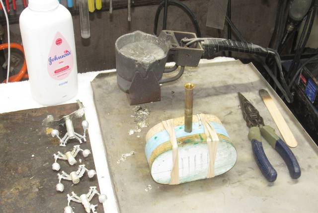
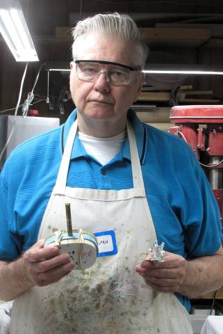
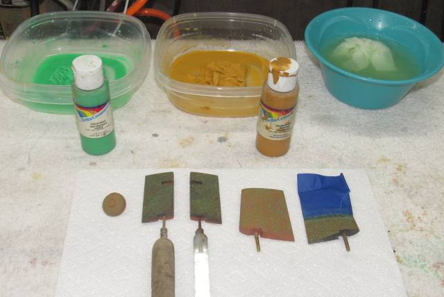
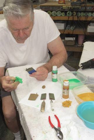
Missing were several closed-chocks and bollard pairs; deck items used to fairlead and tie up to a pier or to make fast small boats and fenders alongside. Since these were needed in some quantity Jake enlisted my aid: I would make a rubber casting tool from his little brass bollard and closed-chock masters, then cast up the required quantity of each from white metal.
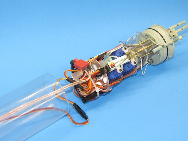
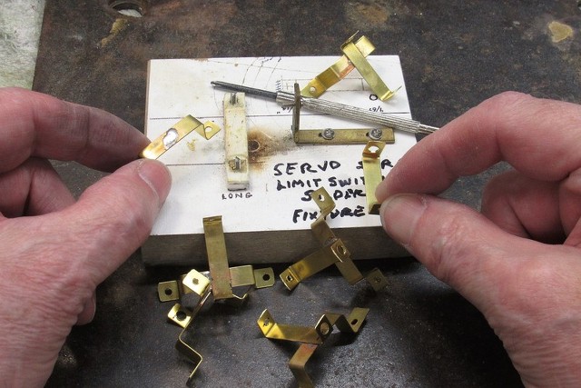
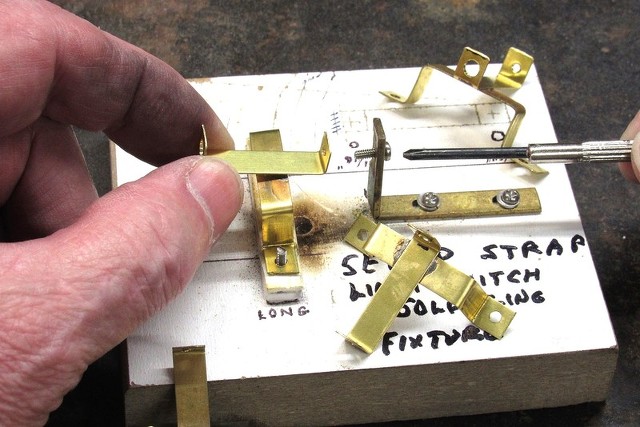
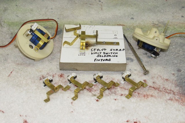
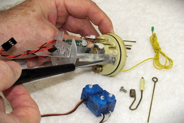
From the last Groton SUBEX 23 regatta I took back a friends two old WTC's we produced years back -- one had a cracked Lexan cylinder that was leaking water into a dry space; and another WTC that had servo, ballast, and motor problems. Just fixed them both up and working to get them back to their owner in time for upcoming summer boat runs. The 2.5" diameter WTC runs his 1/144 SEAWOLF, and the smaller 2" diameter WTC works his 1/144 KILO. Both fixed and ready to be shipped.
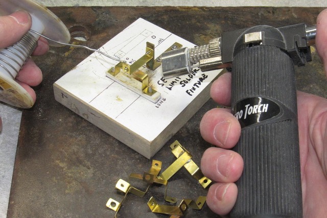
One of the three ganged-together micro servos had gone sour, so that compelled me to break the three servos apart (I glued them together) and install a new servo to replace the broken one. That one task required removing all the devices and linkage elements. What a chore! While I was at it I replaced the original pushrod seals with the 'new-and-improved' pushrod seals I developed recently. I also replaced the bum Lipo-Guard battery protection device; and re-set the ESC. And the low pressure blower electronic switch had burned out, that was replaced as well.
The 2.5" diameter WTC got a replacement clear Lexan cylinder to replace the original, which had cracks in it. Here I've finished a 24-hour annealing in the kitchen oven.
I populated the new, annealed cylinder with all the original goodies from the old cylinder. Leak checked it, and it's good to go.
Did some more work on the below waterline weathering of my long suffering 1/72 THRESHER. Will this beast ever be done?!???!!!!....
.
Missing were several closed-chocks and bollard pairs; deck items used to fairlead and tie up to a pier or to make fast small boats and fenders alongside. Since these were needed in some quantity Jake enlisted my aid: I would make a rubber casting tool from his little brass bollard and closed-chock masters, then cast up the required quantity of each from white metal.

From the last Groton SUBEX 23 regatta I took back a friends two old WTC's we produced years back -- one had a cracked Lexan cylinder that was leaking water into a dry space; and another WTC that had servo, ballast, and motor problems. Just fixed them both up and working to get them back to their owner in time for upcoming summer boat runs. The 2.5" diameter WTC runs his 1/144 SEAWOLF, and the smaller 2" diameter WTC works his 1/144 KILO. Both fixed and ready to be shipped.


One of the three ganged-together micro servos had gone sour, so that compelled me to break the three servos apart (I glued them together) and install a new servo to replace the broken one. That one task required removing all the devices and linkage elements. What a chore! While I was at it I replaced the original pushrod seals with the 'new-and-improved' pushrod seals I developed recently. I also replaced the bum Lipo-Guard battery protection device; and re-set the ESC. And the low pressure blower electronic switch had burned out, that was replaced as well.

The 2.5" diameter WTC got a replacement clear Lexan cylinder to replace the original, which had cracks in it. Here I've finished a 24-hour annealing in the kitchen oven.
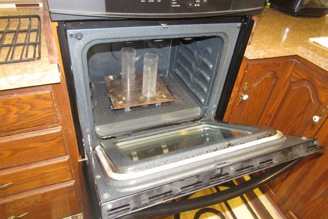
I populated the new, annealed cylinder with all the original goodies from the old cylinder. Leak checked it, and it's good to go.

Did some more work on the below waterline weathering of my long suffering 1/72 THRESHER. Will this beast ever be done?!???!!!!....


Scott Kenny
ACCESS: Above Top Secret
- Joined
- 15 May 2023
- Messages
- 5,999
- Reaction score
- 4,856
Such gorgeous work!
But trust a TM to not make time to get his flotilla into drydock for a hull scrub!
- YN2(SS)
But trust a TM to not make time to get his flotilla into drydock for a hull scrub!
- YN2(SS)
- Joined
- 18 March 2013
- Messages
- 978
- Reaction score
- 2,857
Gotta do something to liven up the display ... bird-poop and marine growth to the rescue!Such gorgeous work!
But trust a TM to not make time to get his flotilla into drydock for a hull scrub!
- YN2(SS)
Nothing beats the Mark I eyeball
- Joined
- 18 March 2013
- Messages
- 978
- Reaction score
- 2,857
When I was a kid you attended school; after-which you did your homework, then sat down in your room or Dad's work-shop and assembled model kits or actually built models, and only broke away when Mom called you to dinner. Fed and the dishes done, you hustled back to the model work, and maybe – just before bed-time, if it was a Friday night – you caught an episode of Sea-Hunt, Twilight Zone, or The Jackie Gleason Show. And when you slept, you dreamed of machines, girls, shop-class, and... girls.
But soon, at the doorstep of manhood, things around you started to jump the rails, as a few of the 'more enlightened' adults who guided my generation began to celebrate failure by looking at our past through the lens of 'today' and promoted socialism as the cure.
And hand-in-hand with this new-think, it became 'acceptable' for young men to either Serve or run off to Canada.
Those same 'enlightened' types eventually came back to the States to remind us of what horrible people we are for believing in, 'the American way'. And... here we are.
Oh, yeah. I remember!
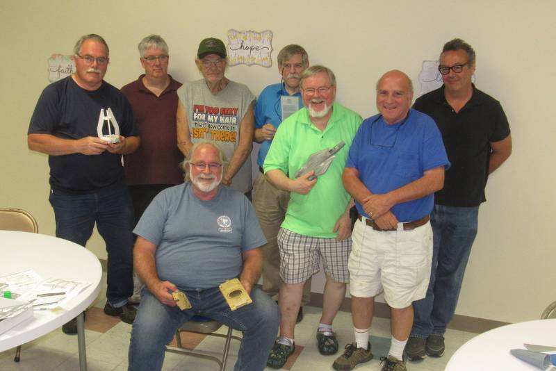
And here's a look at some of the guy's who attended our Virginia Beach Chapter of the International Plastic Model Society (IPMS) monthly meeting last week. Though most retired now, they once held useful jobs. Some former military.
Though most of these bums are in the Twilight of life, we still glue pieces of polystyrene together – it's in their blood. Like the plastic model kits of old, we all are eventually going to go into the same sized box once we assume room-temperature.
For the local clubs 'build-night' I brought along the Trumpeter 1/144 model kit of the Chinese PLAN's Type-092 (XIA class) ballistic missile submarine. I'm in the process of converting this static display piece to run as a proper r/c model submarine.
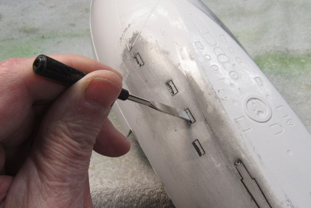
This early Chinese SSBN featured many round vent holes along the surfaces of the fair-water planes and missile hatch fairings. I spent most of the meeting time working to deepen those holes so they would cast realistic looking shadows within. Simple, but tedious work that required the minimum of tools and set-up. Perfect for a build-night away from the well equipped confines of my home shop.
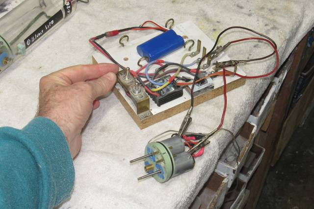
For those who showed an interest in the project I also brought along the SubDriver (SD) used to power, control, and move the model along, the actual hull of the model being of the free-flooding type, serving only as an attractive fairing – all the stuff that needs to be kept dry is within the watertight Lexan cylinder of the SD.
My generation was the last to live, work, fight, and grow under the old standards of American culture. In my time, as a youngster, one's sex was fixed at birth; you were subject to the Draft; public schools steered male students towards 'shop-class'; nearly every boy was assembling static or flying model kits and/or fixing and souping up junked cars; and fist-fights in the school-yard and competitive contact sports were an accepted means of establishing ones 'place' in the group.
Strong, prevailing cultures are built of such foundation blocks.
And back then local hobby shops (remember those?), business break-rooms, churches, and retail stores were most willing to host model club meetings. At no cost.
Today, now that the activity of model kit assembly and model building is on the wain, our now much diminished IPMS membership has secured a once-a-month 'meeting room' at this Unitarian church – for a fee! If the sleeping vagrants don't block the doors.
When I was a boy model-builder clubs were everywhere and each had a huge members list. Model building was encouraged and sponsored by corporate America (Plymouth, Fisher Body, etc.) as well as the local and Federal governments (use of National Guard Armories and Naval Air Stations come to mind).
Yet, today you will see few if any youngsters attending at the few model-building clubs that exist. Just us old farts still living the dream.
These are some of my local peers. See any kids in this group photo?
… and the Craft dies with us.
By time I, and my peers (seen here) had reached mid-life, many of our fellow American's dropped the ball; they changed what we are as a people – transitioning from intelligent, aggressive warriors, and machine-makers into uninformed, sexually confused, entitled, self-hating degenerate slackers wanting nothing more of life than to do as they pleased as their lips suckled on the Government tit.
I've known most of the above guys for nearly a half-century!
This particular meeting was a, 'build-night'. For some odd reason, long ago, it was decided to do, at a meeting, what could be better done in the comfort and easy reach of tools within the home work-space. But, I kinda get the point: it's nice to tinker away at a project while spouting the same old stories among ourselves we've been spouting for decades. Nice to get out of the house once in a while I suppose.
You know you're old when you need a loupe to see what you're doing!
Back home.
My long time modeling buddy, Fred Freketic, needed some work done on his 1/72 THRESHER models SubDriver. Specifically, replacement of the severely cracked clear Lexan cylinder, it had started to leak water. Bad ju-ju!
This involved a lot of work, as I not only had to transfer devices between the bad and good cylinders, I also had to cast new internal bulkheads as there was a significant difference in diameters. Though the old and new cylinders both are listed as 3.5” o.d., and both had internal diameters within industry tolerance, the variance between them forced me to cast up two new internal bulkheads.
Here I'm accessing the free flooding hull to fit the replacement, fully populated and tested SubDriver.
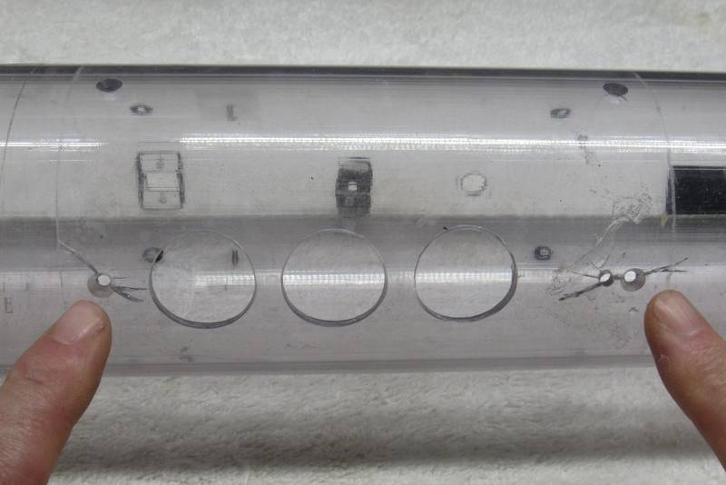
This is the original Lexan cylinder, showing off the massive cracking radiating from the holes that pass machine screws that secured the two internal watertight bulkheads.
Seems the manufacturers of Lexan tube are either skipping or abbreviating the vital annealing process that (should) follow extrusion of the Lexan tube. The consequence is sale of stressed extrusions of tube, which makes them susceptible to cracking after machining. They (the producers of this product) save some pennies. I get hosed by having to work with sub-standard product. Cracks lead to flooding of the SubDriver.
I now anneal each and every SubDriver cylinder I cut to length. Just another pain-in-the-ass courtesy of the Bean-Counters. Be they Chinese or American bean-counters.
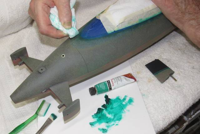
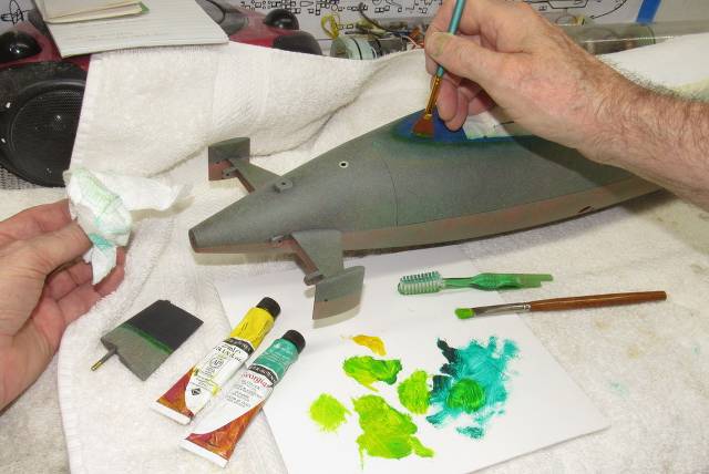
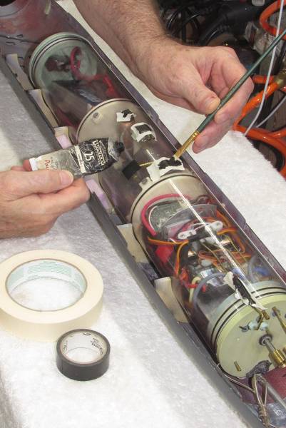
The new cylinder, now equipped with all the transferred devices from the old, cracked cylinder, was placed in the lower hull. However, as I attempted to secure the upper hull in place, something atop the new cylinder was hitting the flotation foam in the upper hull. To find where I first placed masking tape over every projection (manifolds, tire-valve stems, etc.) and slathered atop that tape black artist' oil paint.
Lightly placing the upper hull over the lower hull, the SD's high-spots were indicated on the upper hull foam by black smears. It was a simple and very localized process of slightly digging out the foam so I could once again secure the two hull halves together without any problems.
The black smeared masking tape was pull off the cylinder and discarded.
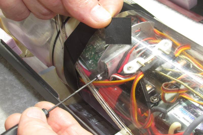
A hole drilled into the side of the Lexan cylinder permits quick adjustment of the angle-keeping device within. That hole is also the Achilles-heel of the SubDriver: should one forget to replace the Electrician's tape closure after making the adjustments, flooding results.
Guess how I know that!?...
As this 1/72 THRESHER model is kinda 'mid-sized', it experiences higher control surface resistance when traveling at speed through the water. I've found that the smaller sized magnets I typically use to make fast the hull and SD linkages were subject to unseating in tight turns and rapid, large deflection movement of fair-water planes and stern planes. So, I elected to go to bigger magnets. Problems solved!
The magnets make installation and removal of the SD to the hull an easy task with no tools required to make/break the linkage interface points.
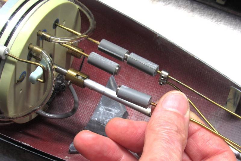
A device that I'm developing a real liking to is a Depth Cruiser. This gadget measures the water pressure and in so doing determines actual depth of the model submarine. The device works in parallel with your commands from the transmitter – you always have authority over the planes. But, if you keep your fat thumb off the stick, the device will work the planes to maintain the boat at the last commanded depth. And it works to keep the boat at that depth until you override it with a new command, where, once again, the DC works to maintain that depth without any input from you.
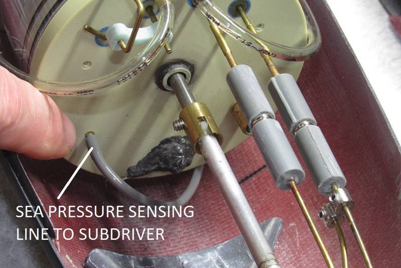
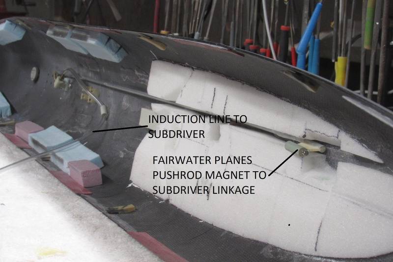
All that is required is a length of hose to provide the DC with ambient pressure so it can work its magic. The DC, mounted on the after dry space device tray, within the Lexan cylinder, gets the pressure input through an internal hose that makes up to the pass-through nipple you see projecting from the after face of the motor-bulkhead. That nipple making up to the external sensing line that runs under the SD where it terminates near the bow of the model submarine.
To insure that any up or down angle the boat takes does not send a false reading to the Depth Cruiser, the inlet side of the sensing hose/line is placed well forward of the model submarines center of rotation. This sensing line runs the entire length of the SD and terminates near the models bow.
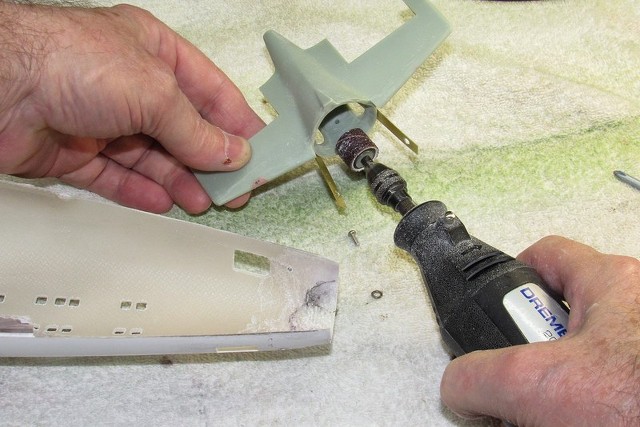
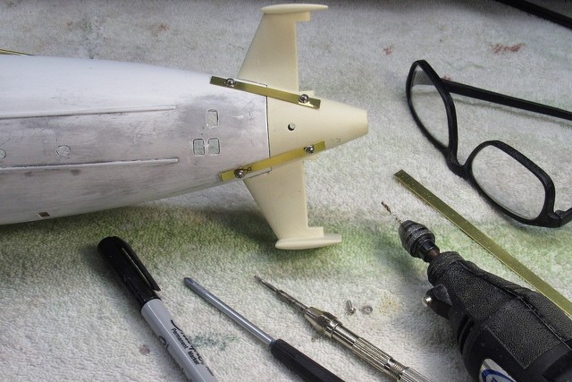
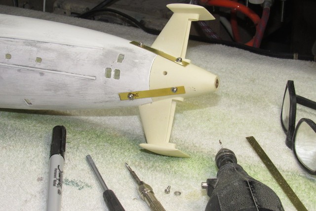
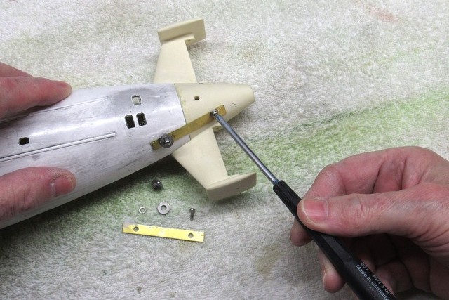
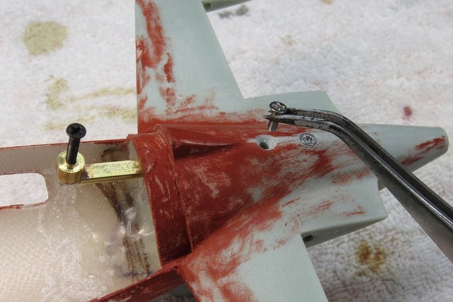
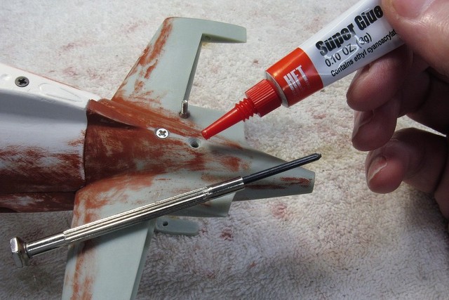
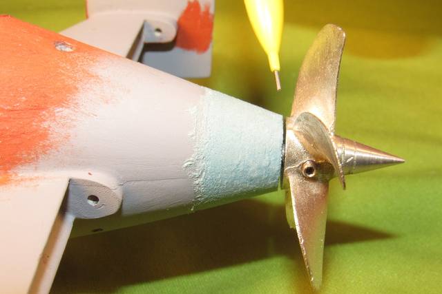
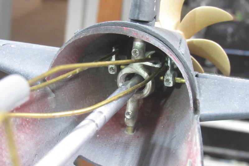
A peek at the white metal rudder yoke and two stern plane horns. All this Tom-foolery needed to make a clear path for the centrally running intermediate drive shaft that interfaces between the SD motor output shaft and propeller shaft.
The first boats of the THRESHER class had extremely small sails (which grew in height and length on the later boats). That equated to very little room within the THRESHER models sail in which to place the SAS ballast sub-system snorkel valve, bow plane operating shaft, and associated linkage.
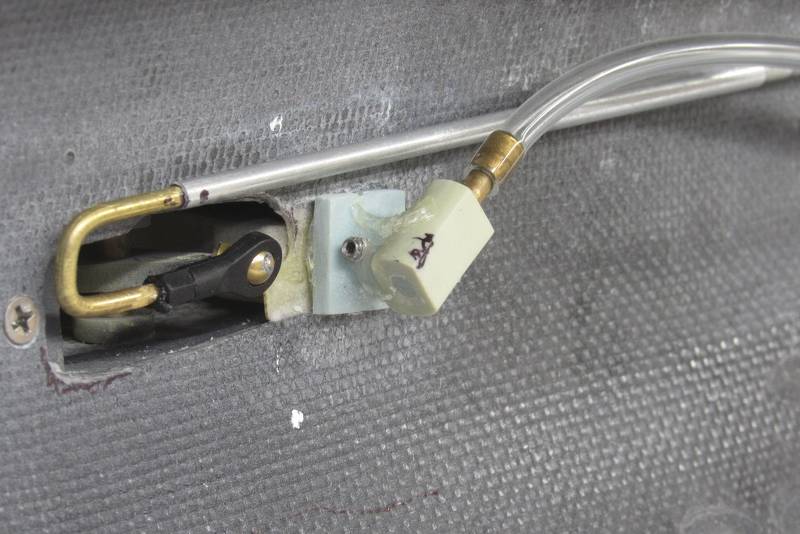
Originally, I employed a magnet at the forward end of the fair-water planes pushrod, but found that the magnet would unseat sometimes, requiring return of the model to the boat stand for re-attachment.
Nuts to that!
Here is the 'new, improved' make-up between fair-water pushrod and fair-water linkage, a helicopter ball-link. No slop. No disconnect. No problems!
Yup. Things are tight in this tiny sail structure.
But soon, at the doorstep of manhood, things around you started to jump the rails, as a few of the 'more enlightened' adults who guided my generation began to celebrate failure by looking at our past through the lens of 'today' and promoted socialism as the cure.
And hand-in-hand with this new-think, it became 'acceptable' for young men to either Serve or run off to Canada.
Those same 'enlightened' types eventually came back to the States to remind us of what horrible people we are for believing in, 'the American way'. And... here we are.
Oh, yeah. I remember!
And here's a look at some of the guy's who attended our Virginia Beach Chapter of the International Plastic Model Society (IPMS) monthly meeting last week. Though most retired now, they once held useful jobs. Some former military.
Though most of these bums are in the Twilight of life, we still glue pieces of polystyrene together – it's in their blood. Like the plastic model kits of old, we all are eventually going to go into the same sized box once we assume room-temperature.

For the local clubs 'build-night' I brought along the Trumpeter 1/144 model kit of the Chinese PLAN's Type-092 (XIA class) ballistic missile submarine. I'm in the process of converting this static display piece to run as a proper r/c model submarine.
This early Chinese SSBN featured many round vent holes along the surfaces of the fair-water planes and missile hatch fairings. I spent most of the meeting time working to deepen those holes so they would cast realistic looking shadows within. Simple, but tedious work that required the minimum of tools and set-up. Perfect for a build-night away from the well equipped confines of my home shop.
For those who showed an interest in the project I also brought along the SubDriver (SD) used to power, control, and move the model along, the actual hull of the model being of the free-flooding type, serving only as an attractive fairing – all the stuff that needs to be kept dry is within the watertight Lexan cylinder of the SD.

My generation was the last to live, work, fight, and grow under the old standards of American culture. In my time, as a youngster, one's sex was fixed at birth; you were subject to the Draft; public schools steered male students towards 'shop-class'; nearly every boy was assembling static or flying model kits and/or fixing and souping up junked cars; and fist-fights in the school-yard and competitive contact sports were an accepted means of establishing ones 'place' in the group.
Strong, prevailing cultures are built of such foundation blocks.
And back then local hobby shops (remember those?), business break-rooms, churches, and retail stores were most willing to host model club meetings. At no cost.
Today, now that the activity of model kit assembly and model building is on the wain, our now much diminished IPMS membership has secured a once-a-month 'meeting room' at this Unitarian church – for a fee! If the sleeping vagrants don't block the doors.

When I was a boy model-builder clubs were everywhere and each had a huge members list. Model building was encouraged and sponsored by corporate America (Plymouth, Fisher Body, etc.) as well as the local and Federal governments (use of National Guard Armories and Naval Air Stations come to mind).
Yet, today you will see few if any youngsters attending at the few model-building clubs that exist. Just us old farts still living the dream.
These are some of my local peers. See any kids in this group photo?
… and the Craft dies with us.
By time I, and my peers (seen here) had reached mid-life, many of our fellow American's dropped the ball; they changed what we are as a people – transitioning from intelligent, aggressive warriors, and machine-makers into uninformed, sexually confused, entitled, self-hating degenerate slackers wanting nothing more of life than to do as they pleased as their lips suckled on the Government tit.
I've known most of the above guys for nearly a half-century!
This particular meeting was a, 'build-night'. For some odd reason, long ago, it was decided to do, at a meeting, what could be better done in the comfort and easy reach of tools within the home work-space. But, I kinda get the point: it's nice to tinker away at a project while spouting the same old stories among ourselves we've been spouting for decades. Nice to get out of the house once in a while I suppose.
You know you're old when you need a loupe to see what you're doing!

Back home.
My long time modeling buddy, Fred Freketic, needed some work done on his 1/72 THRESHER models SubDriver. Specifically, replacement of the severely cracked clear Lexan cylinder, it had started to leak water. Bad ju-ju!
This involved a lot of work, as I not only had to transfer devices between the bad and good cylinders, I also had to cast new internal bulkheads as there was a significant difference in diameters. Though the old and new cylinders both are listed as 3.5” o.d., and both had internal diameters within industry tolerance, the variance between them forced me to cast up two new internal bulkheads.
Here I'm accessing the free flooding hull to fit the replacement, fully populated and tested SubDriver.
This is the original Lexan cylinder, showing off the massive cracking radiating from the holes that pass machine screws that secured the two internal watertight bulkheads.
Seems the manufacturers of Lexan tube are either skipping or abbreviating the vital annealing process that (should) follow extrusion of the Lexan tube. The consequence is sale of stressed extrusions of tube, which makes them susceptible to cracking after machining. They (the producers of this product) save some pennies. I get hosed by having to work with sub-standard product. Cracks lead to flooding of the SubDriver.
I now anneal each and every SubDriver cylinder I cut to length. Just another pain-in-the-ass courtesy of the Bean-Counters. Be they Chinese or American bean-counters.
The new cylinder, now equipped with all the transferred devices from the old, cracked cylinder, was placed in the lower hull. However, as I attempted to secure the upper hull in place, something atop the new cylinder was hitting the flotation foam in the upper hull. To find where I first placed masking tape over every projection (manifolds, tire-valve stems, etc.) and slathered atop that tape black artist' oil paint.
Lightly placing the upper hull over the lower hull, the SD's high-spots were indicated on the upper hull foam by black smears. It was a simple and very localized process of slightly digging out the foam so I could once again secure the two hull halves together without any problems.
The black smeared masking tape was pull off the cylinder and discarded.


A hole drilled into the side of the Lexan cylinder permits quick adjustment of the angle-keeping device within. That hole is also the Achilles-heel of the SubDriver: should one forget to replace the Electrician's tape closure after making the adjustments, flooding results.
Guess how I know that!?...
As this 1/72 THRESHER model is kinda 'mid-sized', it experiences higher control surface resistance when traveling at speed through the water. I've found that the smaller sized magnets I typically use to make fast the hull and SD linkages were subject to unseating in tight turns and rapid, large deflection movement of fair-water planes and stern planes. So, I elected to go to bigger magnets. Problems solved!

The magnets make installation and removal of the SD to the hull an easy task with no tools required to make/break the linkage interface points.
A device that I'm developing a real liking to is a Depth Cruiser. This gadget measures the water pressure and in so doing determines actual depth of the model submarine. The device works in parallel with your commands from the transmitter – you always have authority over the planes. But, if you keep your fat thumb off the stick, the device will work the planes to maintain the boat at the last commanded depth. And it works to keep the boat at that depth until you override it with a new command, where, once again, the DC works to maintain that depth without any input from you.
All that is required is a length of hose to provide the DC with ambient pressure so it can work its magic. The DC, mounted on the after dry space device tray, within the Lexan cylinder, gets the pressure input through an internal hose that makes up to the pass-through nipple you see projecting from the after face of the motor-bulkhead. That nipple making up to the external sensing line that runs under the SD where it terminates near the bow of the model submarine.
To insure that any up or down angle the boat takes does not send a false reading to the Depth Cruiser, the inlet side of the sensing hose/line is placed well forward of the model submarines center of rotation. This sensing line runs the entire length of the SD and terminates near the models bow.

A peek at the white metal rudder yoke and two stern plane horns. All this Tom-foolery needed to make a clear path for the centrally running intermediate drive shaft that interfaces between the SD motor output shaft and propeller shaft.
The first boats of the THRESHER class had extremely small sails (which grew in height and length on the later boats). That equated to very little room within the THRESHER models sail in which to place the SAS ballast sub-system snorkel valve, bow plane operating shaft, and associated linkage.
Originally, I employed a magnet at the forward end of the fair-water planes pushrod, but found that the magnet would unseat sometimes, requiring return of the model to the boat stand for re-attachment.
Nuts to that!
Here is the 'new, improved' make-up between fair-water pushrod and fair-water linkage, a helicopter ball-link. No slop. No disconnect. No problems!

Yup. Things are tight in this tiny sail structure.
- Joined
- 18 March 2013
- Messages
- 978
- Reaction score
- 2,857
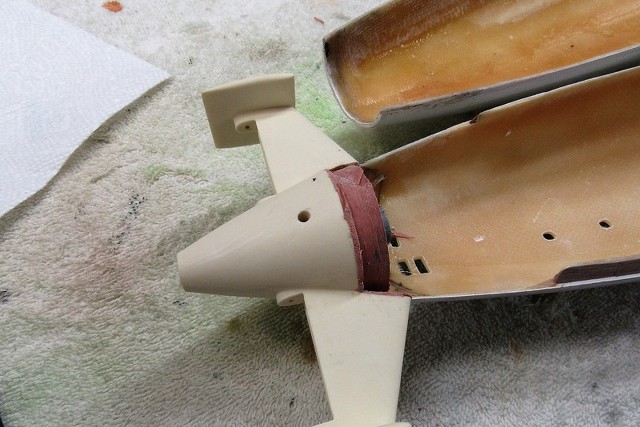
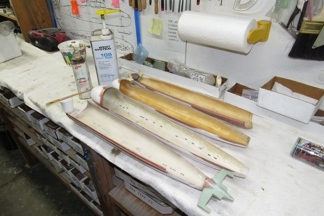
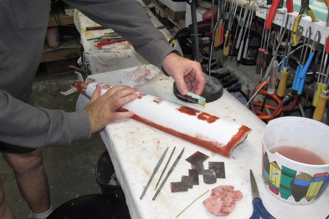
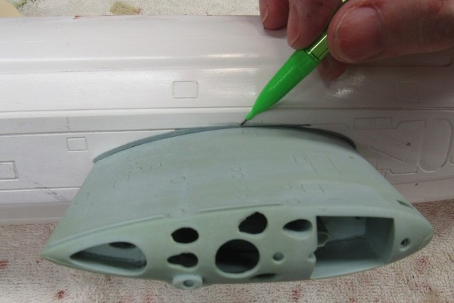
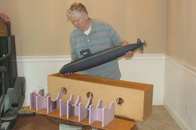
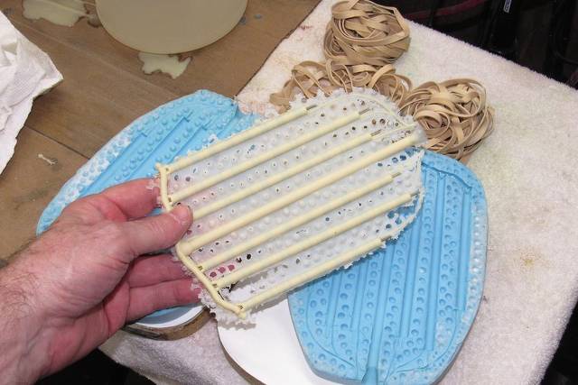
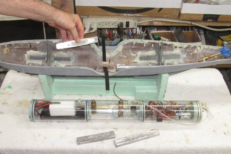
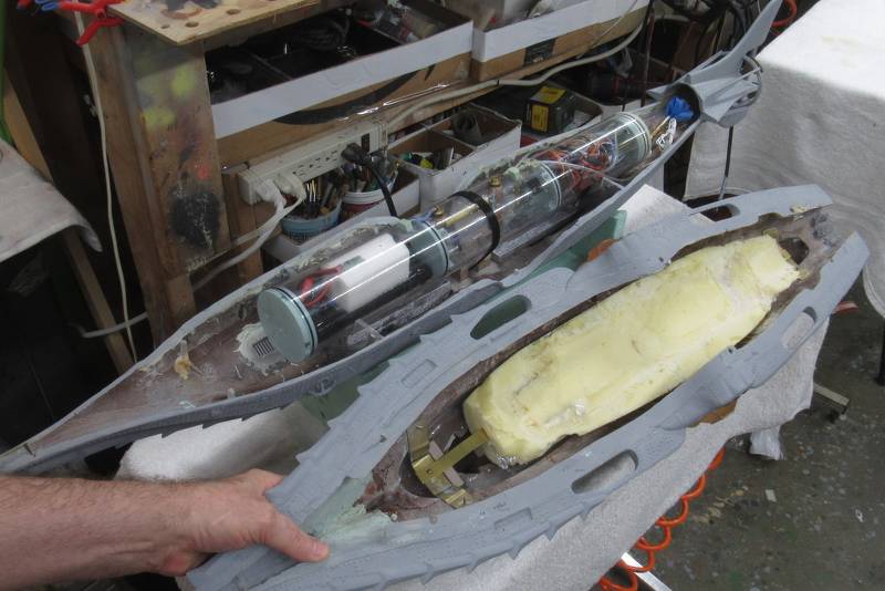
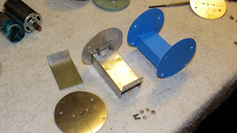
Finally, Jake has completed assembly of the big Disney NAUTILUS model. Time to plunk this monster-of-the-deep into the test-tank. First, I added fixed ballast weight low in the hull to lower its center of mass; then placed buoyant foam up high in the hull to raise its center of buoyancy. The greater the vertical distance between these two points of force, i.e. the CG to the CB, the greater the boats static stability about the roll and pitch axis.
Here I'm placing lead bars down low in the lower hull half. About three-pounds of fixed ballast weight. That was found to be enough (along with the eventual buoyant foam needed to offset all that weight) to stabilize the boat so it doesn't roll too much in a turn or as a consequence of propeller torque.
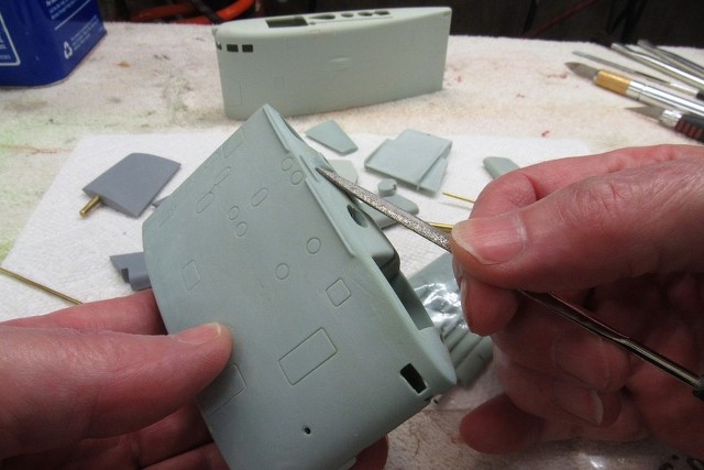
Jake and I produced a single, large hunk of closed-cell polyurethane foam. The goal was to have this buoyant foam up as high in the upper hull as possible, and to conform as tightly as possible to the geometry of the hulls insides. Also, we wanted the ability to make this one big piece of foam removable to ease the task of trimming it down to size so that its upward buoyant force would counter the downward force of the fixed ballast.
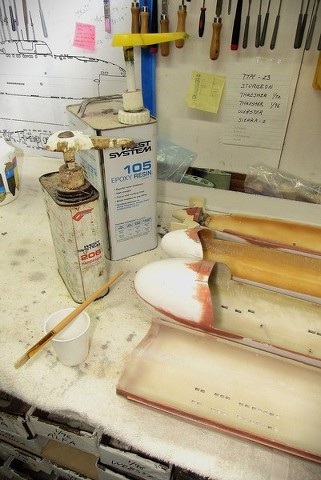
Before catalyzing and pouring in the expanding foam liquid, the upper surfaces within the upper hull were protected with aluminum foil to keep the eventual mass of expanded and hardened foam from sticking.
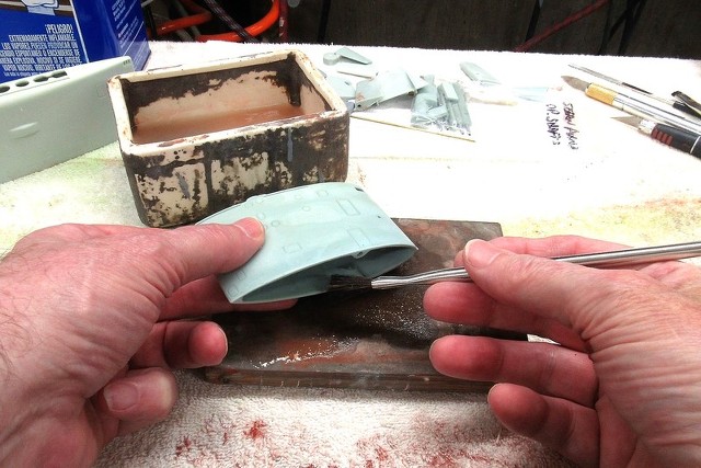
This is what the foam looked like before trimming it to afford clearance between it and the top of the SubDriver (SD). Note the use of brass brackets to hold the foam in place.
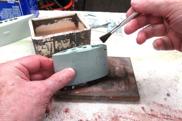
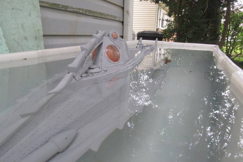
Ballast weights and foam in place, the SD was installed, switched on, and the NAUTILUS' hull buttoned up for the first trial in the test-tank to work out how much – and where – foam had to be cut away and re-positioned to achieve proper submerged and surfaced trim. After a few hours of fiddling with that the boat was pretty much trimmed out.
Initially, commanding a flood of the SD's ballast tank resulted in the models upper surfaces projecting significantly above the waters surface. Too much foam! Repeated testing in the tank guided me as I cut away portions of the buoyant foam until, with a flooded ballast tank, only the tips of the 'alligator eyes' projected above the surface in submerged trim with the boats pitch-angle very close to zero. Perfect!
Blowing the SD's ballast tank dry got the boats upper works this high out of the water. Pretty close, all that was needed at that point was to relocate some of the foam forward – raising the bow up a bit, and lowering the stern to the height of the housed skiffs waterline. That done, the NAUTILUS model was in proper trim for submerged and surfaced operation.
Almost ready for sea-trials!
Years ago I made a 1/96 SKIPJACK class model for my good buddy, Fred Freketic. This year Fred will accompany me to the big all r/c submarine regatta at the Red Clay Resort outdoor 'swimming hole'. In support of that venture I just finished getting his big 1/72 THRESHER model ready, and now it's his little SKIPJACK's turn in the barrel.
Fred reported two problems with this model at the recent Groton SUBEX 23: It was way too bow heavy. As I learned seen enough, Fred had switched to a higher capacity (read: heavier) Lithium-polymer battery, which demanded a re-trimming of the model. The major hang-up was water leaking into the SD's after dry spaces – I found that cracks had formed in the SD's Lexan cylinder permitting the ingress of water from ballast tank to dry spaces. Ouch!
First things first. Re-trimming the boat.
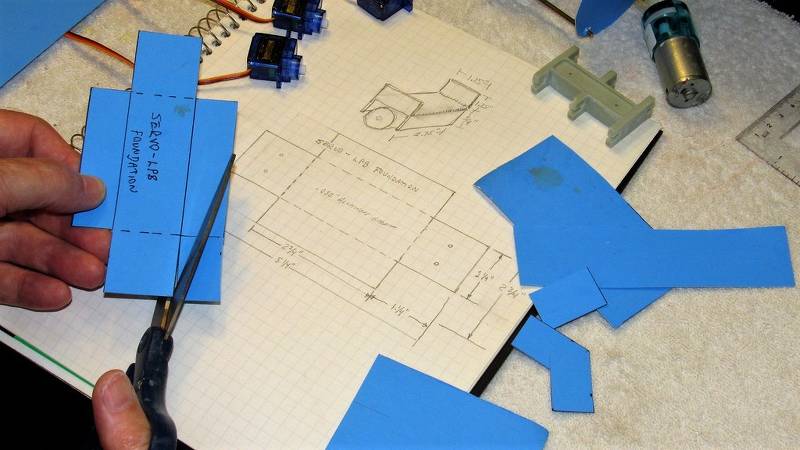
Since the boats trim was thrown way off by the added weight forward, that meant additional buoyant foam had to be jammed into the tight confines of the free-flooding hulls bow. To get an idea of how to shape the eventual gum-drop shaped foam piece I scissored out this cardboard template, and kept chopping away at it until it fit within the bow with little wasted space.
Additional foam was needed up high in the upper hull. To insure non-interference with this additional foam and the SD I made this 'clearance template' out of cardboard, using it as a go/no-go tool as to the thickness of foam I could add without it contacting the top of the SD once the two hull halves were joined.
A basic sheet-metal workers cheat is the use of cardboard mock-ups to verify function and fit of the eventual metal (or other material) assembly. First, a plan is worked out on paper, then a cardboard shape is scissored into life and folded (if required) to shape. The resulting cardboard analog is then fit into place to verify fit. It's an easy matter to make a new cardboard mock-up or simply hack away with scissors on the original until it's right.
With all the cardboard analogs in place things are checked for function and fit.
Once happy with the arrangement the cardboard analogs are removed, unfolded, and used as templates to mark off the actual metal (or GRP, foam, wood, Renshape... whatever!) parts.
The cardboard mock-up saves you wasting time and materials. Paper is cheap, quick, and easy to form. Metal ain't!
The leaking SD was servicable enough for use as I re-trimmed Fred's little SKIPJACK model.
Once I had the boat working properly in both submerged and surfaced trim, I began the process of tearing out all the gear from the original leaking Lexan cylinder and transferring it to a properly annealed Lexan cylinder.
Here the new, annealed, cylinder has been marked off for machining before transferring the bulkheads and devices from old to new cylinder.
It seems that some ten years ago some (if not all) of the manufacturers of extruded Lexan tube either abbreviated or stopped annealing the stressed tube as it squirted out of the die. Lexan cylinder cracking on 'new' Lexan cylinders points to tobservation of mine. I have since made it a practice to perform in-house annealing in the kitchen oven after cutting a Lexan cylinder to length. Fun times!
I'm pointing to the old, cracked Lexan cylinder. I've already populated the new, annealed Lexan cylinder.
Here's the major crack in the original cylinder – this was the worst of the several cracks found on this cylinder; that bad-boy ran right over the after dry space ballast bulkhead O-ring and became the major conduit of water from ballast tank to inside of the after dry space.
Bad ju-ju!!
Industry standard allows for a significant variance between stated and actual cylinder external and internal diameters (the polite term is, 'tolerance'). What that means in the real-world is that one lot of cylinders will differ in dimensions from others. And this situation bit me in the ass on this job, as some of the original bulkheads – sized to fit the old cylinder – were found to be too small in diameter to permit a proper seal of their O-rings within the new cylinder.
Fuck!
I had to cast up more bulkhead blanks and machine them to make ever-so-slight interference fits to the new cylinder, after which I cut in the O-rings grooves.
(I can almost see Bob Martin's smile of recognition as he reads the above).
With all the goodies transferred from bad to good Lexan cylinder, time had come to do a thorough leak test and function validation. Into the drive-way test-tank it went.
Gee... worked first time! I must be getting good at this shit!
OK. The boat trimmed for the new, heavy battery. Check!
The cracked and leaking Lexan cylinder replaced with a tight, annealed one. Check!
Time to box Fred's boats up and await September's SubFest event in far-off Georgia.
Now. To address the boats I want to brings to the event.
A few months back I had gotten my own, new 1/96 SKIPJACK, 1/72 THRESHER, and 1/96 STURGEON models all done with the exception of detailing, flat clear-coat, and final trim and system check-out. Time to re-join those battles. SubFest is just over the horizon.
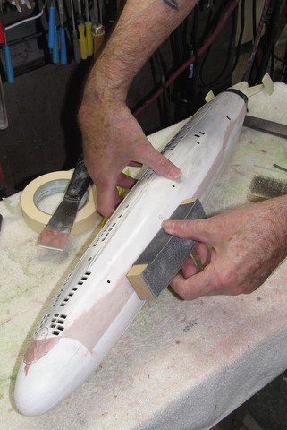
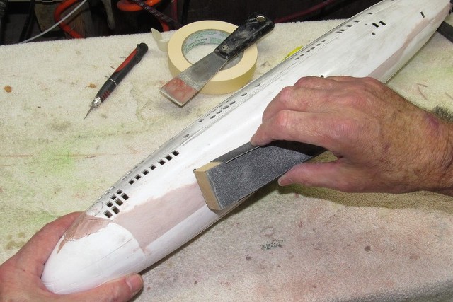
On deck, the 1/96 SKIPJACK. It and its sisters had been sitting on the wall supports for several months, collecting dust, oily mist, and who knows what other crap floats around in this God-awful chamber of horrors I call a shop. Before proceeding with further weathering and touch-up painting those models had to get a complete scrubbing with soap-and-water.
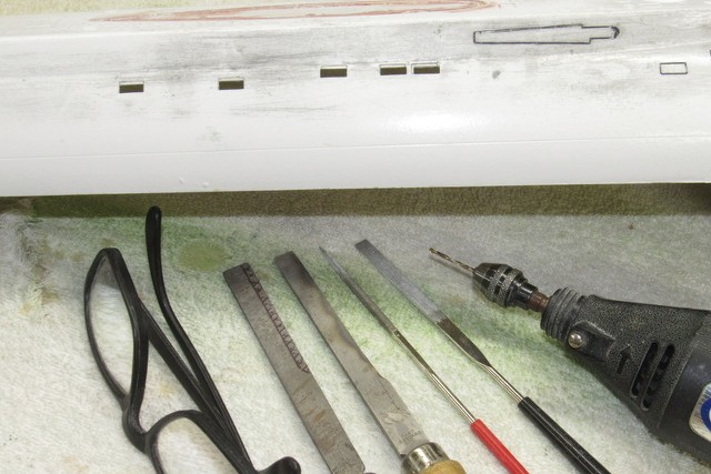
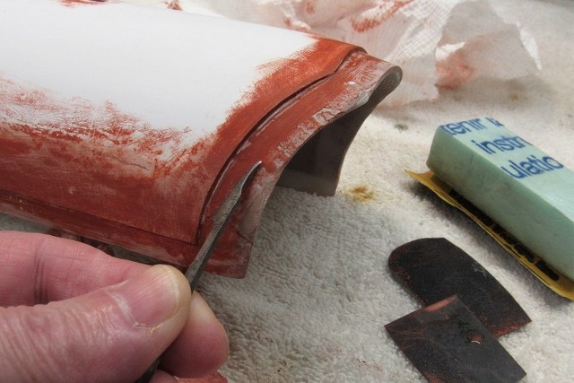
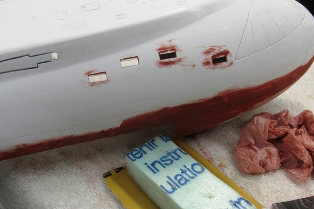
Once scrubbed and rinsed, the SKIPJACK hull and appendages were toweled off and blow-dried with low-pressure air. I let it all sit overnight on a work-table to completely dry out. Time had come to address the two escape-trunk deck hatches, McCann rescue chamber hold-down pad-eyes, and prep those metal items for painting and installation.
The four pad-eyes, each formed from a strand of .013” diameter copper conductor were bent to shape. .013” holes previously drilled about the circumference of an escape-trunk McCann rescue chamber seat.
One set of pad-eyes forward of the sail, and the other way back aft over the engineering spaces. (That's eight pad-eyes for those of you keeping score at home).
However, after all the priming, painting and protective clear-coating those little holes I initially drilled got fouled up, so I had to bore them out again, with a .013” bit.
In addition to the eight pad-eye holes I also had to bore out the two holes in the deck that would pass a length of wire representing the McCann rescue chamber down-haul cable that ran from an on-board cable reel and escape marker buoy … more on that later.
A common hand-drill is too slow and bulky (and its chuck likely too gross to hold and center a small bit); and the typical moto-tool is too massive and produces too much torque to give you a 'feel' for the job as you bore into the work.
What is needed is a drill motor that is high-speed, low-torque, and so light in your hand that you can 'feel' the drilling as it progresses. So, in pursuit of such a tool, I converted these cheap-ass Harbor Freight 'Micro Engraver' tools to serve as small drill bit drivers.
Fortunately the chuck of these little drills is just a collar with a .092” bore, that collar equipped with a set-screw to lock the bits shank in place. So, all I had to do was take a selection of small drill bits, ranging in sizes from .030” to .013” and secure each in a .092” shank (formed from some polyurethane discarded sprue stock) and Presto-Blamo... a mini-drill motor and a fair selection of small bits to fit it.
The smaller the drill-bit the faster it has to be spun, but the feed pressure has to be minimized and the bit driven into the bore with quick, light jabs to clear the bits flutes of kerf. Otherwise the bit will overheat and... SNAP!... the bit is broken, its tip buried deep where you're likely never to extract it, ruining the work. Dumb Ass!
Small bits demand high speed, very light feed pressure, and constant jabbing to keep the flutes unclogged.
Increasing the utility of this little drill-motor I turned a brass extension collar that permits me to mount any of the many types of .125” diameter shanked rotary bits I have at hand. Here you see both the drill-motor and a selection of bits all efficiently packaged together on this handy caddie.
Here I'm placing lead bars down low in the lower hull half. About three-pounds of fixed ballast weight. That was found to be enough (along with the eventual buoyant foam needed to offset all that weight) to stabilize the boat so it doesn't roll too much in a turn or as a consequence of propeller torque.
Jake and I produced a single, large hunk of closed-cell polyurethane foam. The goal was to have this buoyant foam up as high in the upper hull as possible, and to conform as tightly as possible to the geometry of the hulls insides. Also, we wanted the ability to make this one big piece of foam removable to ease the task of trimming it down to size so that its upward buoyant force would counter the downward force of the fixed ballast.
Before catalyzing and pouring in the expanding foam liquid, the upper surfaces within the upper hull were protected with aluminum foil to keep the eventual mass of expanded and hardened foam from sticking.
This is what the foam looked like before trimming it to afford clearance between it and the top of the SubDriver (SD). Note the use of brass brackets to hold the foam in place.
Ballast weights and foam in place, the SD was installed, switched on, and the NAUTILUS' hull buttoned up for the first trial in the test-tank to work out how much – and where – foam had to be cut away and re-positioned to achieve proper submerged and surfaced trim. After a few hours of fiddling with that the boat was pretty much trimmed out.

Initially, commanding a flood of the SD's ballast tank resulted in the models upper surfaces projecting significantly above the waters surface. Too much foam! Repeated testing in the tank guided me as I cut away portions of the buoyant foam until, with a flooded ballast tank, only the tips of the 'alligator eyes' projected above the surface in submerged trim with the boats pitch-angle very close to zero. Perfect!

Blowing the SD's ballast tank dry got the boats upper works this high out of the water. Pretty close, all that was needed at that point was to relocate some of the foam forward – raising the bow up a bit, and lowering the stern to the height of the housed skiffs waterline. That done, the NAUTILUS model was in proper trim for submerged and surfaced operation.
Almost ready for sea-trials!
Years ago I made a 1/96 SKIPJACK class model for my good buddy, Fred Freketic. This year Fred will accompany me to the big all r/c submarine regatta at the Red Clay Resort outdoor 'swimming hole'. In support of that venture I just finished getting his big 1/72 THRESHER model ready, and now it's his little SKIPJACK's turn in the barrel.
Fred reported two problems with this model at the recent Groton SUBEX 23: It was way too bow heavy. As I learned seen enough, Fred had switched to a higher capacity (read: heavier) Lithium-polymer battery, which demanded a re-trimming of the model. The major hang-up was water leaking into the SD's after dry spaces – I found that cracks had formed in the SD's Lexan cylinder permitting the ingress of water from ballast tank to dry spaces. Ouch!
First things first. Re-trimming the boat.
Since the boats trim was thrown way off by the added weight forward, that meant additional buoyant foam had to be jammed into the tight confines of the free-flooding hulls bow. To get an idea of how to shape the eventual gum-drop shaped foam piece I scissored out this cardboard template, and kept chopping away at it until it fit within the bow with little wasted space.


Additional foam was needed up high in the upper hull. To insure non-interference with this additional foam and the SD I made this 'clearance template' out of cardboard, using it as a go/no-go tool as to the thickness of foam I could add without it contacting the top of the SD once the two hull halves were joined.

A basic sheet-metal workers cheat is the use of cardboard mock-ups to verify function and fit of the eventual metal (or other material) assembly. First, a plan is worked out on paper, then a cardboard shape is scissored into life and folded (if required) to shape. The resulting cardboard analog is then fit into place to verify fit. It's an easy matter to make a new cardboard mock-up or simply hack away with scissors on the original until it's right.

With all the cardboard analogs in place things are checked for function and fit.
Once happy with the arrangement the cardboard analogs are removed, unfolded, and used as templates to mark off the actual metal (or GRP, foam, wood, Renshape... whatever!) parts.
The cardboard mock-up saves you wasting time and materials. Paper is cheap, quick, and easy to form. Metal ain't!
The leaking SD was servicable enough for use as I re-trimmed Fred's little SKIPJACK model.
Once I had the boat working properly in both submerged and surfaced trim, I began the process of tearing out all the gear from the original leaking Lexan cylinder and transferring it to a properly annealed Lexan cylinder.
Here the new, annealed, cylinder has been marked off for machining before transferring the bulkheads and devices from old to new cylinder.

It seems that some ten years ago some (if not all) of the manufacturers of extruded Lexan tube either abbreviated or stopped annealing the stressed tube as it squirted out of the die. Lexan cylinder cracking on 'new' Lexan cylinders points to tobservation of mine. I have since made it a practice to perform in-house annealing in the kitchen oven after cutting a Lexan cylinder to length. Fun times!
I'm pointing to the old, cracked Lexan cylinder. I've already populated the new, annealed Lexan cylinder.
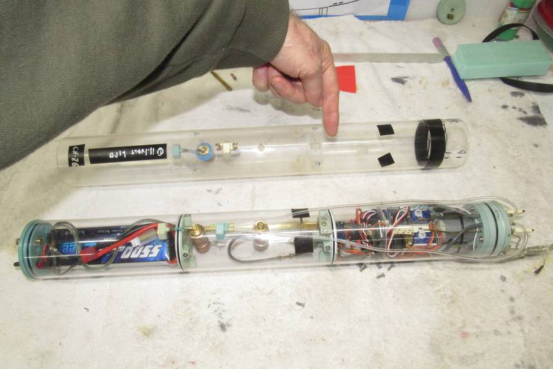
Here's the major crack in the original cylinder – this was the worst of the several cracks found on this cylinder; that bad-boy ran right over the after dry space ballast bulkhead O-ring and became the major conduit of water from ballast tank to inside of the after dry space.
Bad ju-ju!!

Industry standard allows for a significant variance between stated and actual cylinder external and internal diameters (the polite term is, 'tolerance'). What that means in the real-world is that one lot of cylinders will differ in dimensions from others. And this situation bit me in the ass on this job, as some of the original bulkheads – sized to fit the old cylinder – were found to be too small in diameter to permit a proper seal of their O-rings within the new cylinder.
Fuck!
I had to cast up more bulkhead blanks and machine them to make ever-so-slight interference fits to the new cylinder, after which I cut in the O-rings grooves.
(I can almost see Bob Martin's smile of recognition as he reads the above).
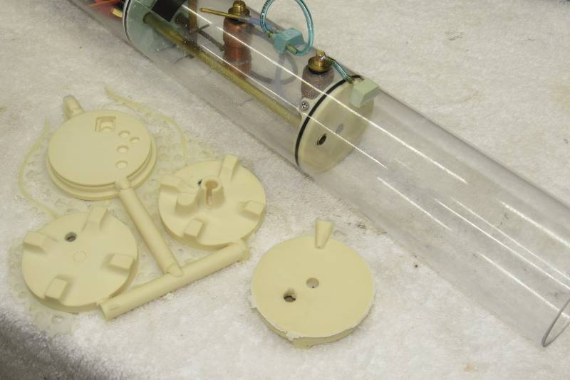
With all the goodies transferred from bad to good Lexan cylinder, time had come to do a thorough leak test and function validation. Into the drive-way test-tank it went.
Gee... worked first time! I must be getting good at this shit!
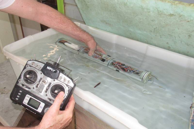
OK. The boat trimmed for the new, heavy battery. Check!
The cracked and leaking Lexan cylinder replaced with a tight, annealed one. Check!
Time to box Fred's boats up and await September's SubFest event in far-off Georgia.
Now. To address the boats I want to brings to the event.
A few months back I had gotten my own, new 1/96 SKIPJACK, 1/72 THRESHER, and 1/96 STURGEON models all done with the exception of detailing, flat clear-coat, and final trim and system check-out. Time to re-join those battles. SubFest is just over the horizon.
On deck, the 1/96 SKIPJACK. It and its sisters had been sitting on the wall supports for several months, collecting dust, oily mist, and who knows what other crap floats around in this God-awful chamber of horrors I call a shop. Before proceeding with further weathering and touch-up painting those models had to get a complete scrubbing with soap-and-water.

Once scrubbed and rinsed, the SKIPJACK hull and appendages were toweled off and blow-dried with low-pressure air. I let it all sit overnight on a work-table to completely dry out. Time had come to address the two escape-trunk deck hatches, McCann rescue chamber hold-down pad-eyes, and prep those metal items for painting and installation.

The four pad-eyes, each formed from a strand of .013” diameter copper conductor were bent to shape. .013” holes previously drilled about the circumference of an escape-trunk McCann rescue chamber seat.
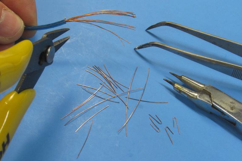
One set of pad-eyes forward of the sail, and the other way back aft over the engineering spaces. (That's eight pad-eyes for those of you keeping score at home).

However, after all the priming, painting and protective clear-coating those little holes I initially drilled got fouled up, so I had to bore them out again, with a .013” bit.
In addition to the eight pad-eye holes I also had to bore out the two holes in the deck that would pass a length of wire representing the McCann rescue chamber down-haul cable that ran from an on-board cable reel and escape marker buoy … more on that later.

A common hand-drill is too slow and bulky (and its chuck likely too gross to hold and center a small bit); and the typical moto-tool is too massive and produces too much torque to give you a 'feel' for the job as you bore into the work.
What is needed is a drill motor that is high-speed, low-torque, and so light in your hand that you can 'feel' the drilling as it progresses. So, in pursuit of such a tool, I converted these cheap-ass Harbor Freight 'Micro Engraver' tools to serve as small drill bit drivers.

Fortunately the chuck of these little drills is just a collar with a .092” bore, that collar equipped with a set-screw to lock the bits shank in place. So, all I had to do was take a selection of small drill bits, ranging in sizes from .030” to .013” and secure each in a .092” shank (formed from some polyurethane discarded sprue stock) and Presto-Blamo... a mini-drill motor and a fair selection of small bits to fit it.

The smaller the drill-bit the faster it has to be spun, but the feed pressure has to be minimized and the bit driven into the bore with quick, light jabs to clear the bits flutes of kerf. Otherwise the bit will overheat and... SNAP!... the bit is broken, its tip buried deep where you're likely never to extract it, ruining the work. Dumb Ass!
Small bits demand high speed, very light feed pressure, and constant jabbing to keep the flutes unclogged.

Increasing the utility of this little drill-motor I turned a brass extension collar that permits me to mount any of the many types of .125” diameter shanked rotary bits I have at hand. Here you see both the drill-motor and a selection of bits all efficiently packaged together on this handy caddie.
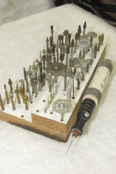
Scott Kenny
ACCESS: Above Top Secret
- Joined
- 15 May 2023
- Messages
- 5,999
- Reaction score
- 4,856
Very nice!
Where did you get your Barbel-class hulls, I'm thinking that might be a nice place to start. Just planning on adding the hardware for working torpedo tubes, like the evil Submariner I am... Won't add the working bits immediately, but want the tubes in there for weight and balance from the start.
Where did you get your Barbel-class hulls, I'm thinking that might be a nice place to start. Just planning on adding the hardware for working torpedo tubes, like the evil Submariner I am... Won't add the working bits immediately, but want the tubes in there for weight and balance from the start.
- Joined
- 18 March 2013
- Messages
- 978
- Reaction score
- 2,857
BARBLE class r/c model submarine hulls were available through Nautilus Drydocks, Remotecontrol submarines | The Nautilus Drydocks (rc-submarine.com) though currently out of the production cycle. Give them a ring. Here are some shots of a unit I finished and operated for several years. These kits were originally designed, produced and marketed by David Manley's outfit, Small World Models.
Here are some 1/72 scale gas-propelled torpedo and launcher thought starters for you:

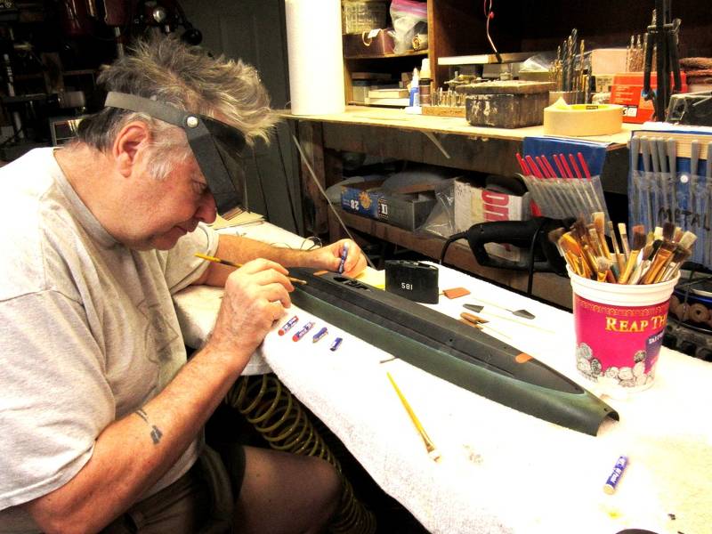
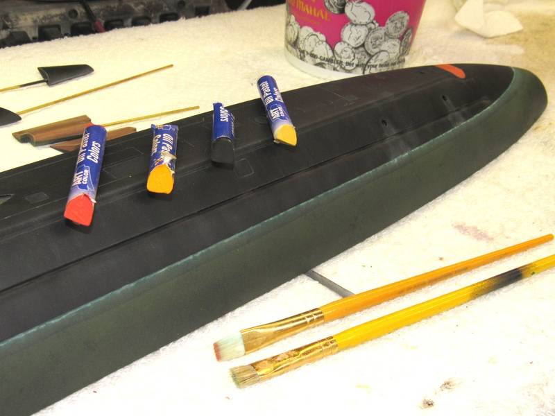


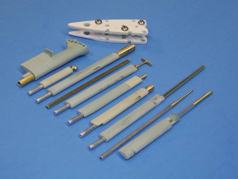


Here are some 1/72 scale gas-propelled torpedo and launcher thought starters for you:
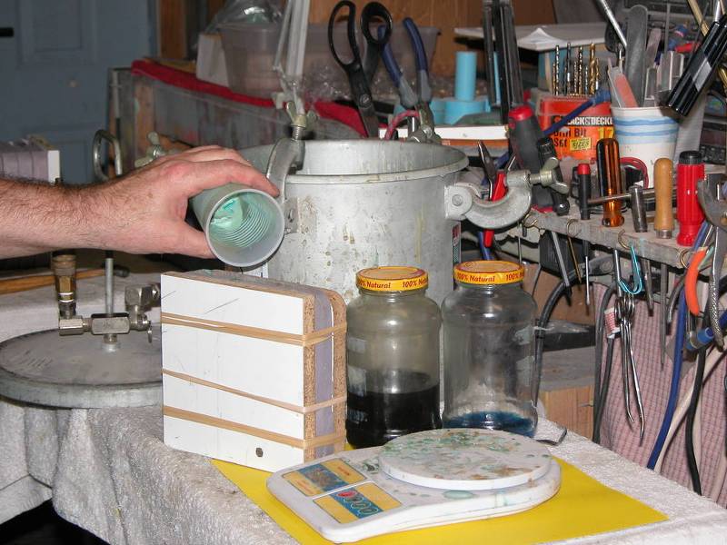

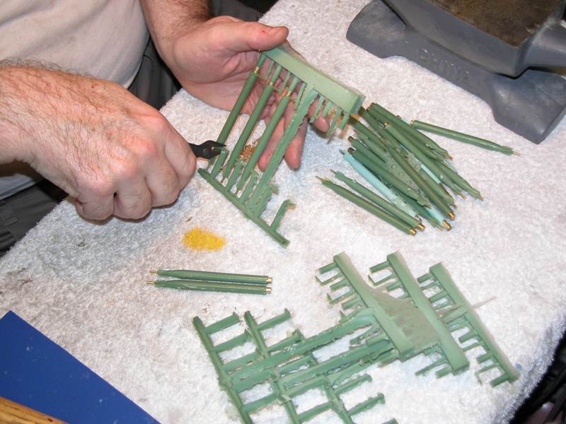
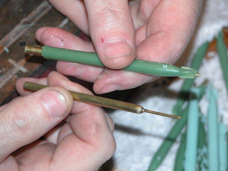


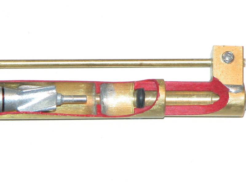
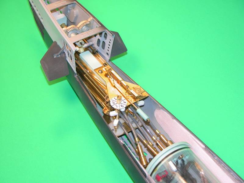
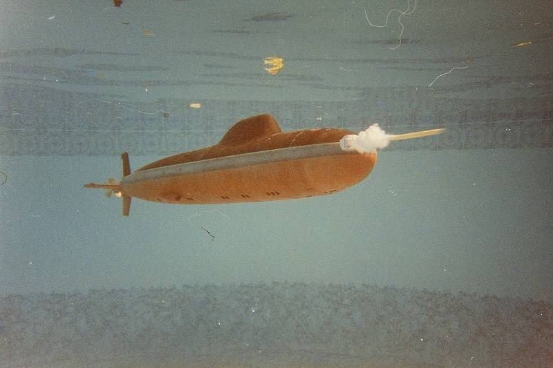
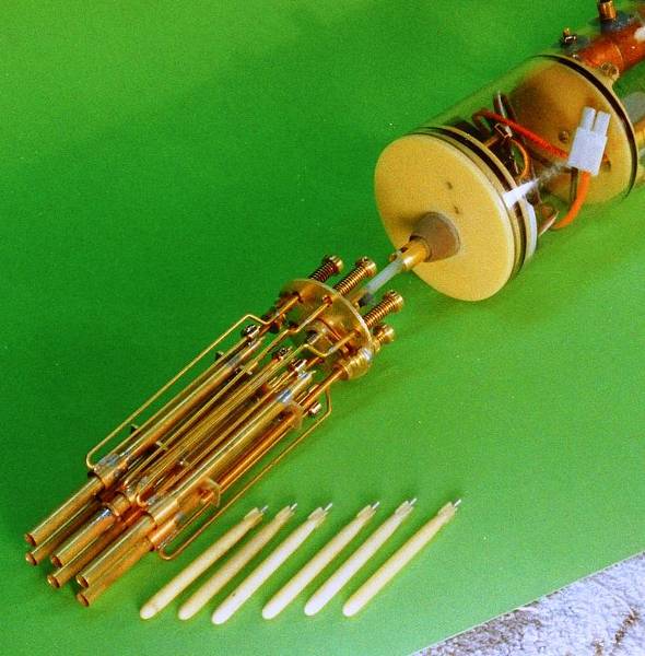

Scott Kenny
ACCESS: Above Top Secret
- Joined
- 15 May 2023
- Messages
- 5,999
- Reaction score
- 4,856
Thanks!!!
Man that's going to be a tight fit in there, even if I go with minimum length tubes...
A Mk48 torpedo is 530mm in diameter and 5800mm long, so to scale would be ~5.52mm and ~60.42mm (that 4% difference really shows up, doesn't it). Whole tube would be another 25-50mm longer than the fish. (sometimes it's easier to think in metric) Call it 0.217" in diameter and 2.379" long, whole tube on the order of 4.375" long, that will put the front end of the SubDriver cylinder roughly under the leading edge of the sail... (where's the :headscratch: emoji in this forum?!?)
The only other thing I want to add is a flashing LED for when the EMBT blow happens or I lose radio contact. Either one happens, flashing LED starts going off on the masthead or periscope head. Going to be a right pain to wire that in and make it watertight... dielectric grease here I come...
Exactly what I want! May have to get really creative with the forward dry space to have enough room for batteries, torpedo servo(s), and torpedo tubes, though... Gonna have to build model first to figure out the right length watertight cylinder.BARBLE class r/c model submarine hulls were available through Nautilus Drydocks, Remotecontrol submarines | The Nautilus Drydocks (rc-submarine.com) though currently out of the production cycle. Give them a ring. Here are some shots of a unit I finished and operated for several years. These kits were originally designed, produced and marketed by David Manley's outfit, Small World Models.
(various images deleted for space)
(images deleted for space)
That's quite a rat's nest, and do those bow planes actually retract as well as dive/surface?!?Here are some 1/72 scale gas-propelled torpedo and launcher thought starters for you:
(images deleted for space)
That looks like the right setup for a Barbel class, 3 over 3. Wider torpedo room than the Gato/Balao/Tench fleet boats.
Man that's going to be a tight fit in there, even if I go with minimum length tubes...
A Mk48 torpedo is 530mm in diameter and 5800mm long, so to scale would be ~5.52mm and ~60.42mm (that 4% difference really shows up, doesn't it). Whole tube would be another 25-50mm longer than the fish. (sometimes it's easier to think in metric) Call it 0.217" in diameter and 2.379" long, whole tube on the order of 4.375" long, that will put the front end of the SubDriver cylinder roughly under the leading edge of the sail... (where's the :headscratch: emoji in this forum?!?)
The only other thing I want to add is a flashing LED for when the EMBT blow happens or I lose radio contact. Either one happens, flashing LED starts going off on the masthead or periscope head. Going to be a right pain to wire that in and make it watertight... dielectric grease here I come...


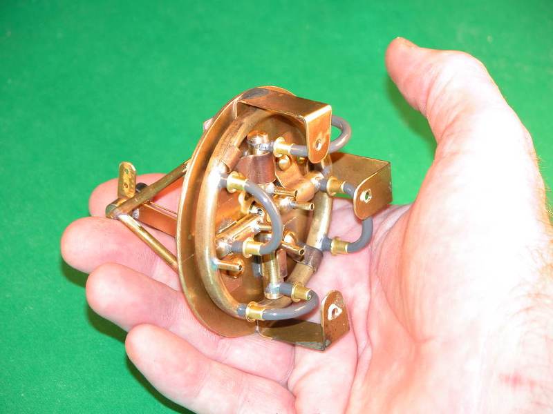

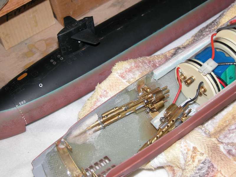

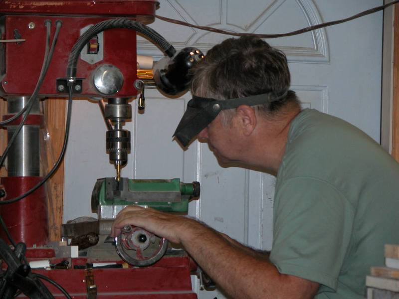
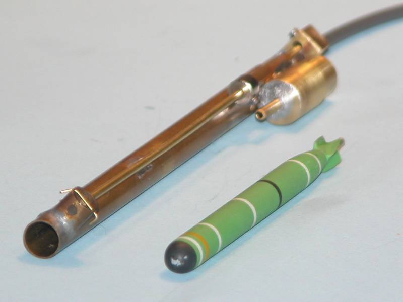

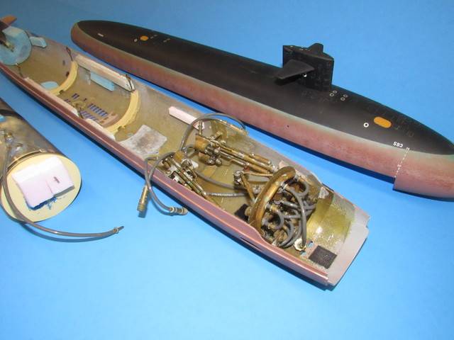

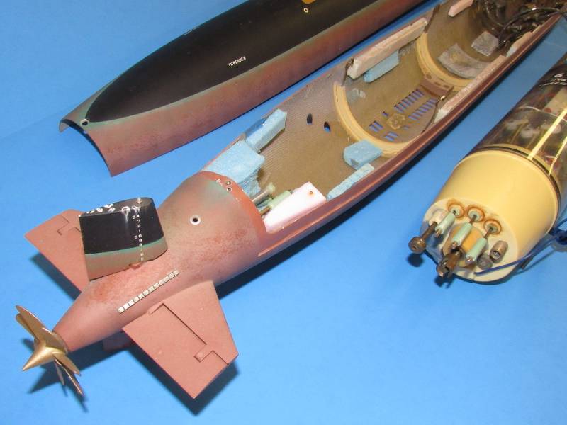
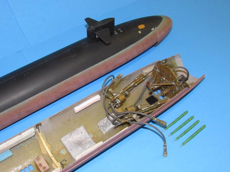

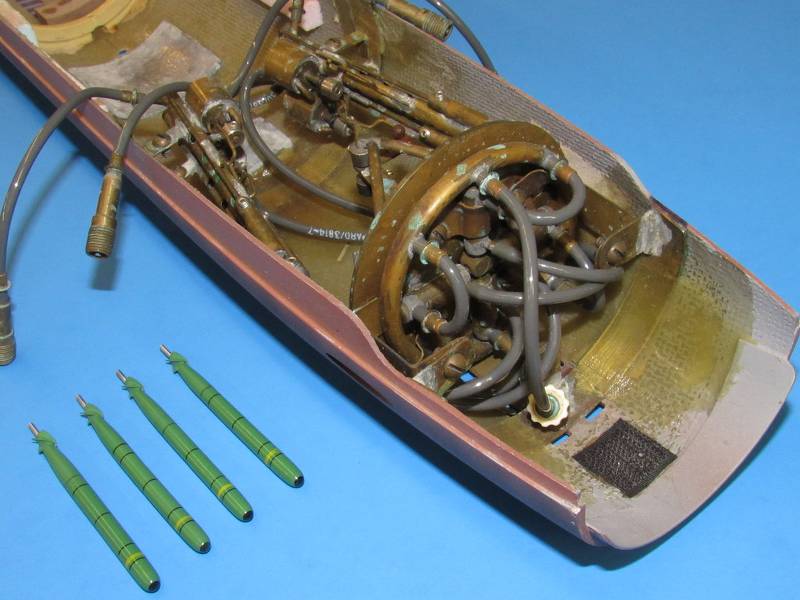
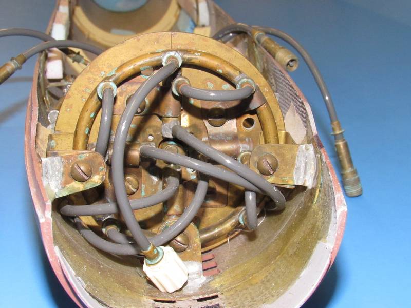
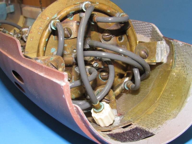
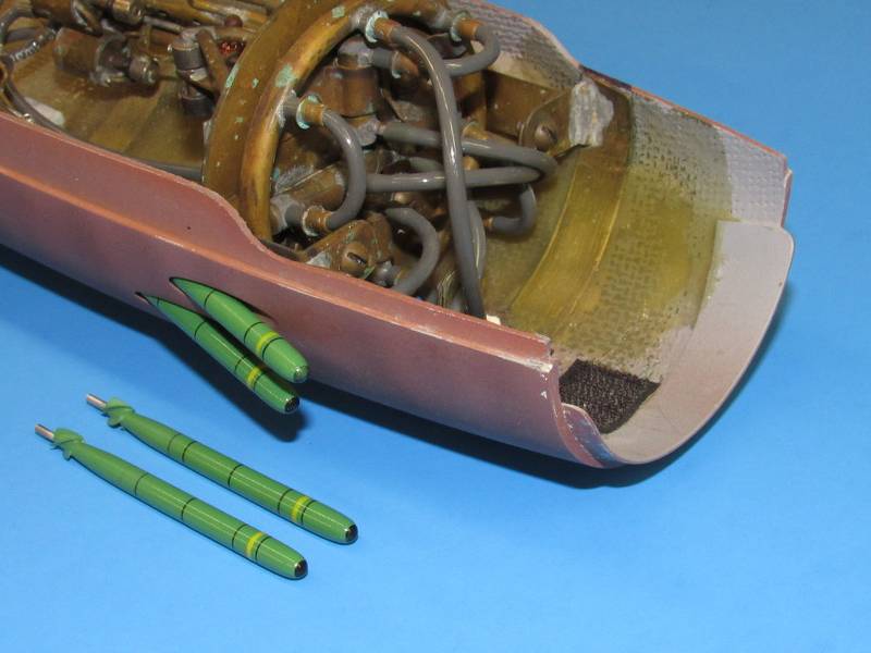
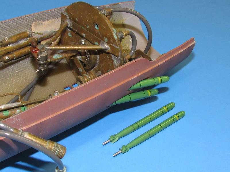
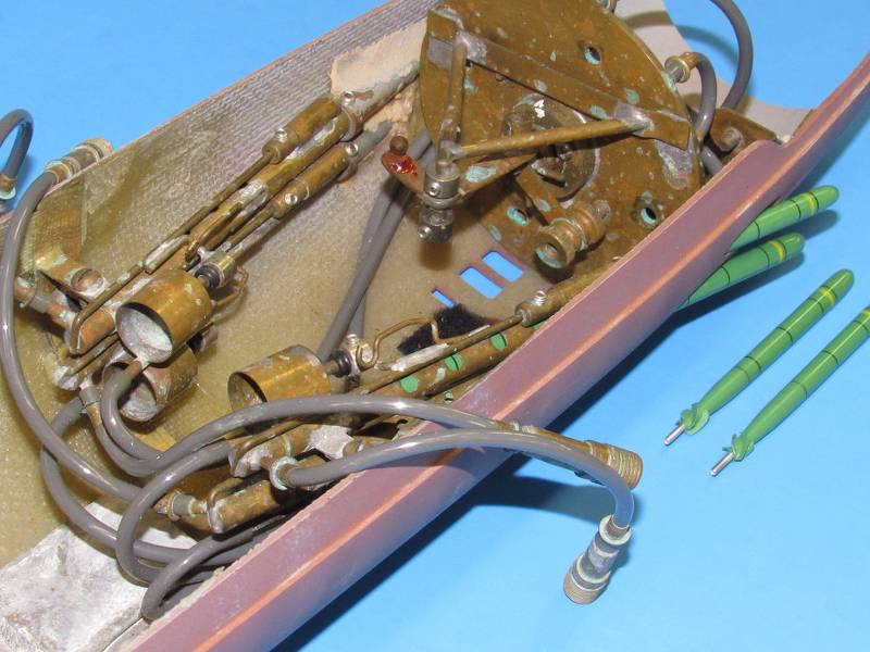
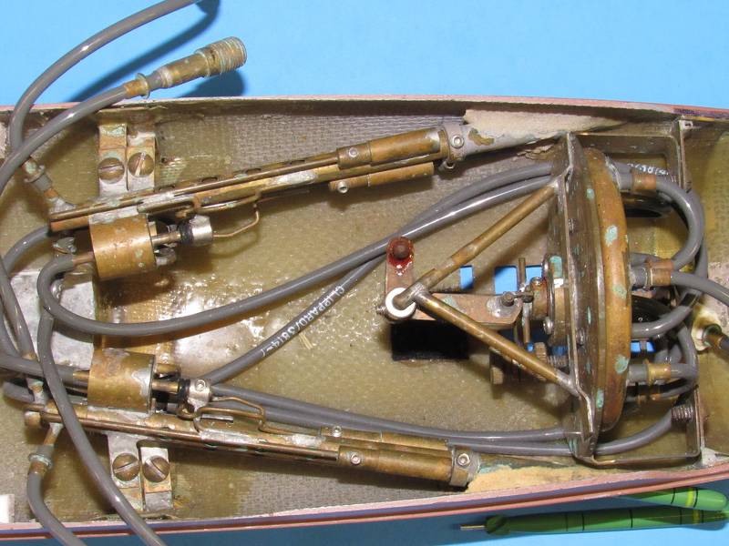

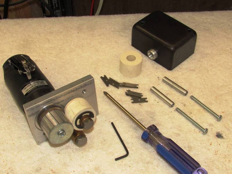


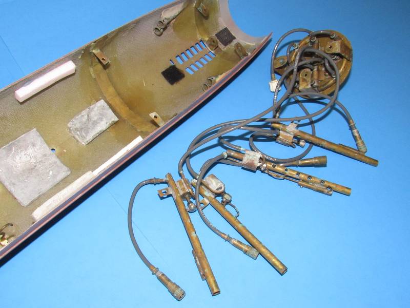

- Joined
- 13 June 2007
- Messages
- 2,029
- Reaction score
- 2,251
Amazing work there - really appreciate the sharing, in detail, that you've done throughout this thread.Here's my 1/96 THRESHER complete with a 1/96 launchers and gas propelled weapons:
David (Torpedoman's Mate in another life)
Enjoy the Day! Mark
- Joined
- 18 March 2013
- Messages
- 978
- Reaction score
- 2,857
Yes, the bow planes deploy and retract on command.Thanks!!!
Exactly what I want! May have to get really creative with the forward dry space to have enough room for batteries, torpedo servo(s), and torpedo tubes, though... Gonna have to build model first to figure out the right length watertight cylinder.BARBLE class r/c model submarine hulls were available through Nautilus Drydocks, Remotecontrol submarines | The Nautilus Drydocks (rc-submarine.com) though currently out of the production cycle. Give them a ring. Here are some shots of a unit I finished and operated for several years. These kits were originally designed, produced and marketed by David Manley's outfit, Small World Models.
(various images deleted for space)
(images deleted for space)
That's quite a rat's nest, and do those bow planes actually retract as well as dive/surface?!?Here are some 1/72 scale gas-propelled torpedo and launcher thought starters for you:
(images deleted for space)
That looks like the right setup for a Barbel class, 3 over 3. Wider torpedo room than the Gato/Balao/Tench fleet boats.
Man that's going to be a tight fit in there, even if I go with minimum length tubes...
A Mk48 torpedo is 530mm in diameter and 5800mm long, so to scale would be ~5.52mm and ~60.42mm (that 4% difference really shows up, doesn't it). Whole tube would be another 25-50mm longer than the fish. (sometimes it's easier to think in metric) Call it 0.217" in diameter and 2.379" long, whole tube on the order of 4.375" long, that will put the front end of the SubDriver cylinder roughly under the leading edge of the sail... (where's the :headscratch: emoji in this forum?!?)
The only other thing I want to add is a flashing LED for when the EMBT blow happens or I lose radio contact. Either one happens, flashing LED starts going off on the masthead or periscope head. Going to be a right pain to wire that in and make it watertight... dielectric grease here I come...


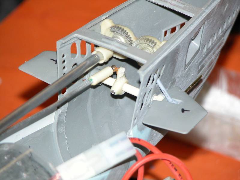
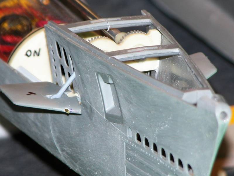


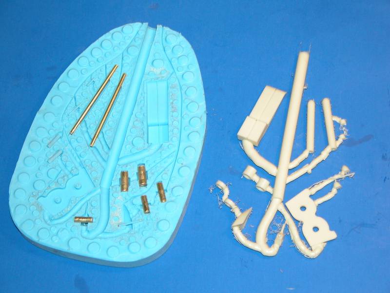
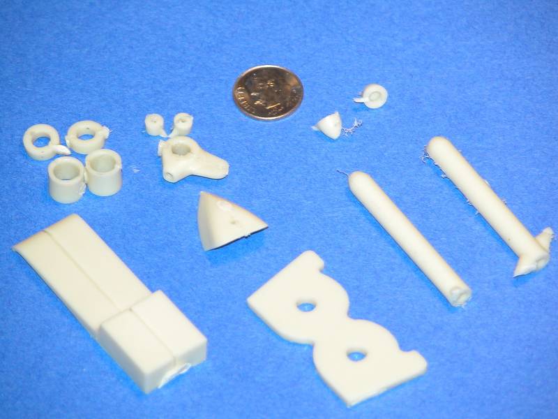


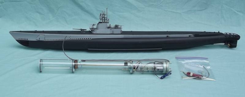

David
Scott Kenny
ACCESS: Above Top Secret
- Joined
- 15 May 2023
- Messages
- 5,999
- Reaction score
- 4,856
That is so cool!!!
Similar threads
-
 General Theory of Optimal Combat Vehicle Design: A project
- Started by shin_getter
- Replies: 9
-

-
-
-
 UK deterrent with cruise missiles
- Started by uk 75
- Replies: 9