
You are using an out of date browser. It may not display this or other websites correctly.
You should upgrade or use an alternative browser.
You should upgrade or use an alternative browser.
Merriman's Submarine Modelling Masterclass
- Thread starter merriman
- Start date


- Joined
- 18 March 2013
- Messages
- 978
- Reaction score
- 2,851
Bob was very kind. Ellie and I worked for his outfit, The Nautilus Drydocks, for over ten-years -- up to my recent retirement. Thank you for posting, Scott. Most thoughtful.
David
The Horrible
David
The Horrible


southwestforests
ACCESS: Secret
- Joined
- 28 June 2012
- Messages
- 435
- Reaction score
- 561
While the Disney Nautilus from Jules Verne's novel 20,000 Leagues Under the Sea is a worldwide classic submarine, that's the big problem, it is Disney's Nautilus and not the one Jules Verne wrote.


- Joined
- 18 March 2013
- Messages
- 978
- Reaction score
- 2,851
INTRODUCTION
Ellie and I registered our business, D&E Miniatures, sometime in the late-70's. We became a proper business at that point and carried on with our work of manufacturing and selling small display and commemorative models to individuals and institutions. That move put us on the map and secured a tax exempt number.
Other than that, becoming a sole proprietary business made little difference to our day to day activities: I was still in the Navy, Ellie was wrangling two Alpha teenagers and worked at Electric Boats 'canteen', and we built models for money on the side.
Time had come to step up the business, so we chummed the waters. A brochure listing our services was prepared and hundreds of them were mailed out -- mostly to big industrial players, movie studios (though the studio system was crumbling then, I reasoned that there might still be some meat on those bones), schools of Engineering (those with tow tanks and/or wind tunnels), a few shipyards, NASCAR sponsors, airlines, and cruise lines. In those days, before the Internet, the connective tissue between businesses was the big, green Thomas Register books. Within those pages we found our target audience.
And, damned if that didn't work!
In no time we began to be wooed by members of the defense industry. Models to be displayed at the many trade shows such businesses attended domestically and abroad. We soon found that working for people who promoted and fostered, 'man's greatest outdoor activity' was good money. No big surprise to me, but a bit of a culture-shock for Ellie to learn that those who make, promote, and sell weapons of war, and their vendors, make a good living.
One of my duty-stations was the dive-locker aboard the destroyer tender, USS VULCAN. I spent my entire four years working the ships tied up at the Naval Base, Norfolk. No underway time, no duty-section; a regular day-time job. And those four years I worked at the south end of the base, in a double-wide tailor with the other VULCAN divers. I pulling down base-pay, dive-pay, and sea-pay! During the day a ships husbandry diver; by night and weekends, back at home, Ellie and I were busy building models for The Lords of War. Life was good!
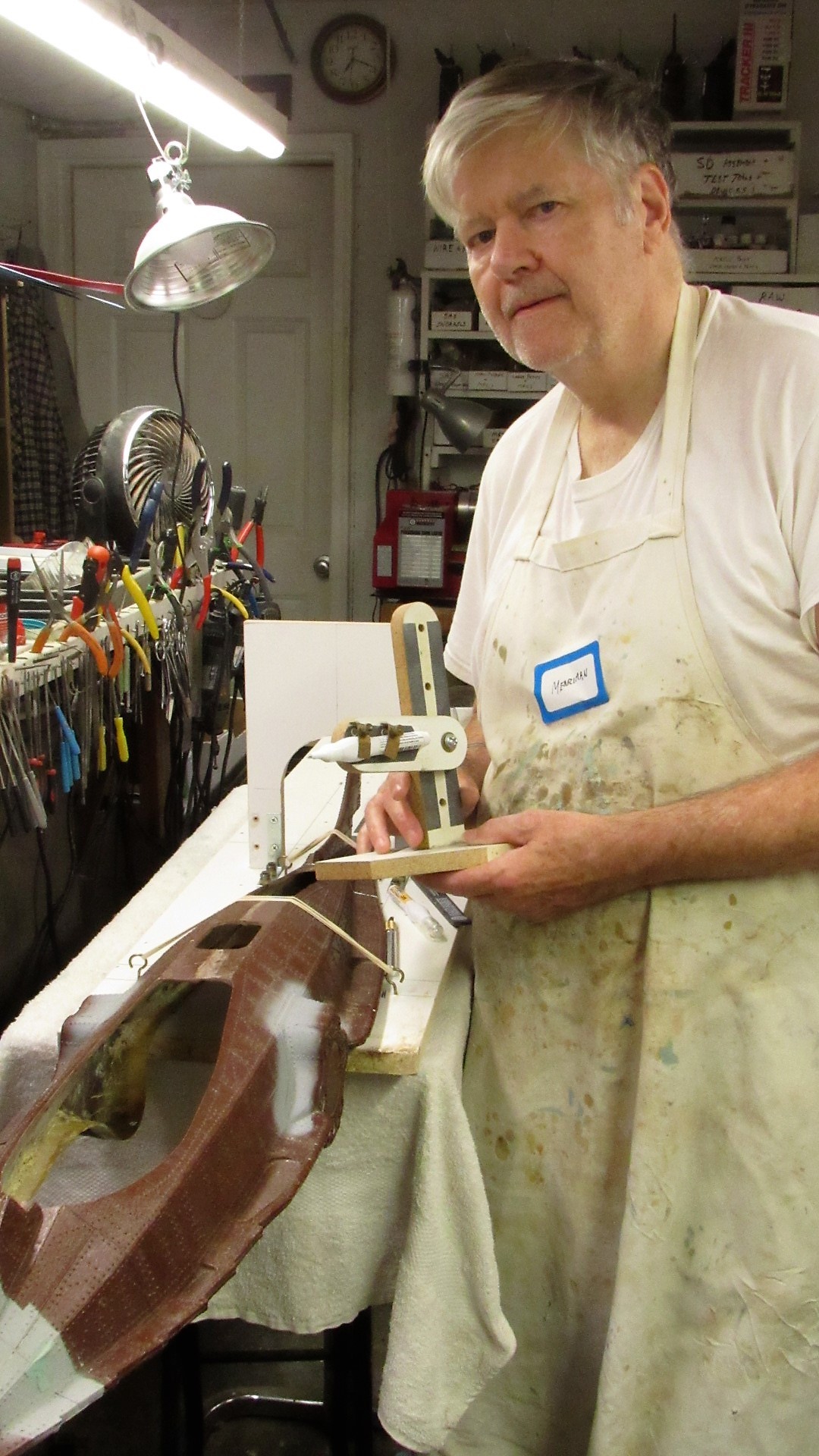
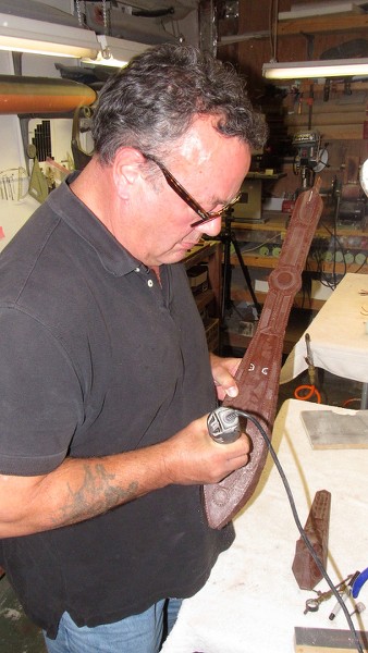
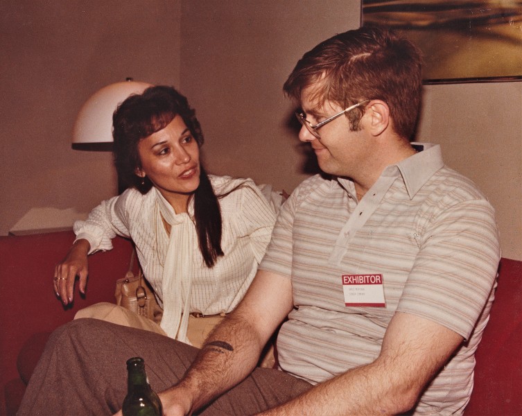
We built a lot of 'interesting' models for the defense trade. On occasion a client would put the two of us up at the convention site to baby-sit the display pieces; to be on hand if the models needed moving or repair. Someone snapped this shot of us at one of the D.C. Navy League sponsored defense conventions as we took a breather in the clients 'hospitality suite'.

Typically, the division of labor went like this: Ellie did the production work and screened inquiries. I did the research, layout, masters, tools, and detail stuff. That put the RASHER job firmly in my court.
But, though we were kept busy with the defense clients, I did accept the occasion commission from private individuals. Which was the case with the subject presented here: a 1/180 scale, highly detailed model of the USS RASHER, SSR 269. The client sent me a stack of photos and his suggestion that I work up the display using the then available Revell LIONFISH plastic model kit.
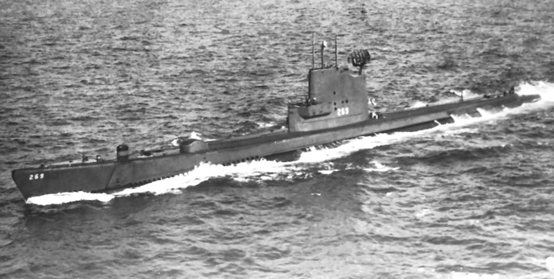
The RASHER and her sisters were WW-2 era GATO class diesel boats modified to serve as radar picket submarine -- advance scouts for fleet battle groups. Hence the new designation SSR. The Migraine-3 program defined and oversaw the modification. The Migraine-3 boats, of which the RASHER was a member, were extensively reworked. They were lengthened, their stern tubes removed to make room for the increased compliment, huge air-search radars installed atop their GUPPY like sails, and a dedicated air-control center installed to coordinate friendly air operations as well as presenting the tactical situation to the battle-group Commander. But, the days of the SSR's were brief as AWAC aircraft, satellites, and SSN's quickly took over the roll of battle-group point-man.
DBF.
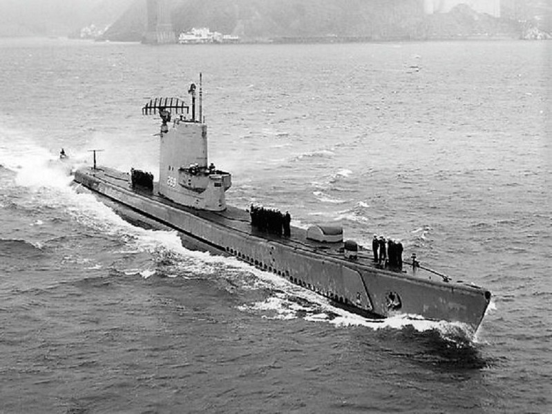
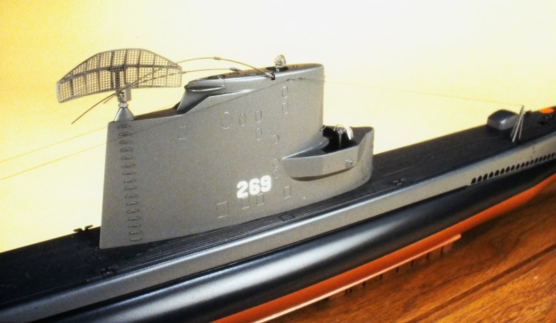
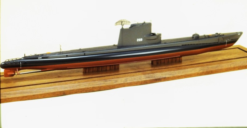
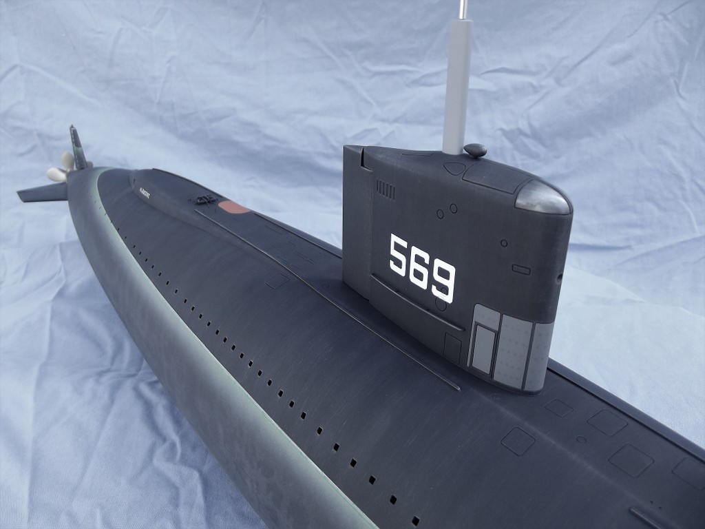
This picture of RASHER shows her a short time after the Migraine-3 conversion, as the bulbous height-finding radar just abaft the sail and smaller 'homing beacon' radar near the turtle-back are still in place. These items were soon removed leaving only the big sail mounted BPS-2 radar antenna to tell the world that RASHER was a radar picket submarine.
The projecting bridge 'wings' permitted the conning officer and lookouts to get a view aft without their line of sight being to badly blocked by the elongated sail.
(My apologies for the grainy quality of the following in-work and beauty shots that chronicle creation of the RASHER display. I documented this work in the late 80's, before I embraced digital photography. The pictures that follow were recently copied digitally from the original, and slightly time diminished, color slide positive film and black & white negative film I've retained through the years).
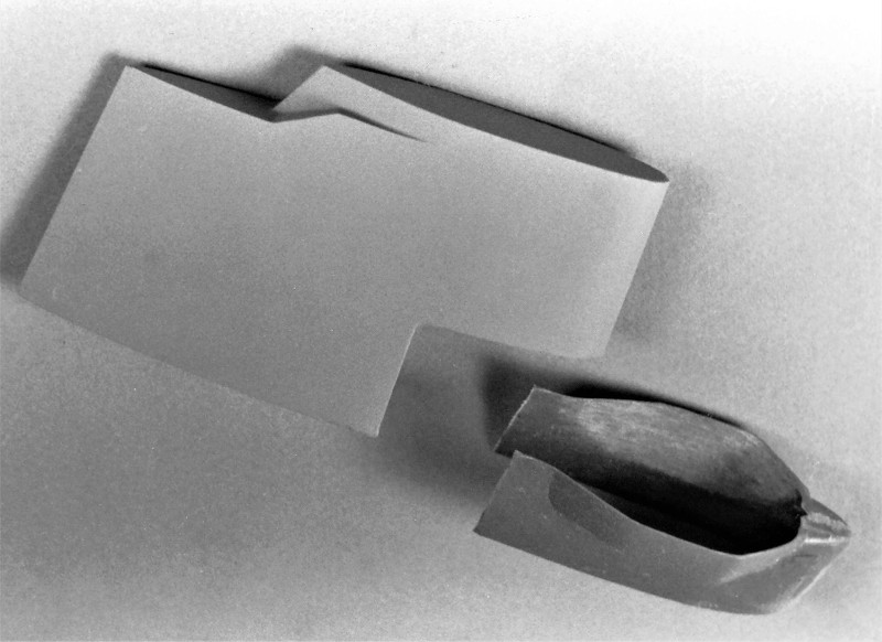
Three major tasks presented themselves as I converted the LIONFISH kit to the Migraine-3 RASHER: Lengthen the hull and capture the 'knuckle' where the forward end of the hull extension piece butted up ugly to the rest of the submarines bow; manufacture of an entirely new sail fairwater with its weird bridge wings; and creation of that big BPS-2 drag inducing parachute of a radar antenna mounted atop that sail.
THE HULL
The Migraine-3 boats were lengthened to make room for the CIC space and additional equipment.
To extend the kits hull 25-scale-feet I bought a second LIONFISH kit and grafted a portion of that to the display hull. The graft done at the hulls maximum breadth so as not to spoil the natural curve of the hull. Once the hull was lengthened I would later ugly up the hull at the point near the bow where the hull extension was performed on the actual boat.
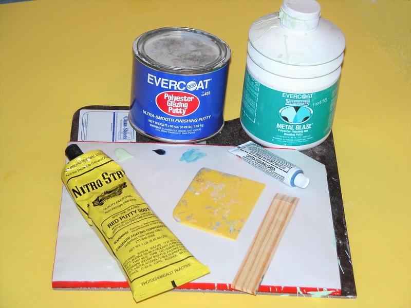
Automotive filler -- classified as a thermosetting type plastic -- is a mixture of polyester resin and finally ground, inert 'filler' to thicken the product. The catalyzed goo can be applied, in mass, to a surface in need of re-contouring without fear of sagging. Unlike air-dry putties (like my favorite, Nitro-Stan) that can't be put on too thickly, with a catalyzed filler the thicker you put it on, the hotter it gets, and the quicker it changes state from semi-liquid to hard mass.
For this discussion I'll use the trade name of a familiar brand of filler: 'Bondo'.
The after end of the extension segment attached at or near the operations compartment forward bulkhead -- a bit forward of the conning tower-fairwater leading edge. This constant diameter extension of the pressure hull, and saddle type ballast tanks that surrounded it, resulted in a nasty looking 'knuckle' at the forward end of the extension. This, of course, ruined the smooth lines of the hull so close to the sharply curving bow. Oh, well... function over beauty, as they say.
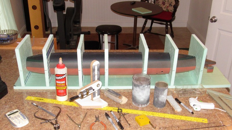
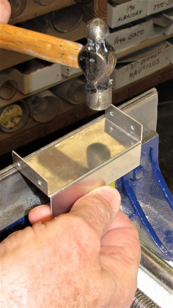
I built an external radial frame from .065" thick polystyrene sheet. This external reference frame girdling the hull where the forward end of the hull extension piece was to be. That frame, at its outer edge, having the same geometry as the after end of the supposed extension.
I screeded on catalyzed Bondo to the height of the external frame both fore and aft, feathering the filler to the surface of the hull. With just a few careful passes of a broad bladed putty knife, I had roughed out a credible looking 'knuckle' to the hull lines forward.
Some filing and sanding, a bit more Bondo, more sanding, then Nitro-Stan air-dry touch-up putty to address file and sanding marks, yet more sanding, and the hull was ready for gray primer.
Bondo was also used to fill the concave portions of the bow and stern torpedo tube shutter doors. Also, a bit of Bondo was used to fill the gap between the wooden sail and GRP bridge structure once they were glued together.
A word to the wise: Bondo like fillers are for re-contouring and filling of significant gaps. The Nitro-Stan air-dry lacquer based touch-up putty, on the other hand, is for very shallow gaps and tool-marks.
Don't use hobby-shop sold air-dry putties or paints... they're crap; formulated to be safe, not effective. Green-Stuff and the like, if applied too heavily, will take years to thoroughly harden. Nitro-Stan is much quicker to dry owing to that products extremely volatile solvents.
Hint: If the product labeling does not warn of cancer, warts, lung damage, distemper, Ebola, or your dick falling off, the stuff is useless! The good stuff -- putties, primers, paint, and clear coat systems -- will be found at automotive supply houses and Ebay.
GLASS REINFORCED PLASTIC (GRP)
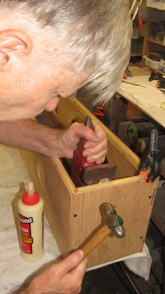
fiberglass layup is the process of forming tough, light weight, thin walled structures by encapsulating strands of fiberglass with a hardened plastic resin. The resin, once it changes state from liquid to solid, provides the stiffness. The embedded glass strands endows the structure with great strength. Just the right material from which to fabricate the open bridge structure at the leading edge of the sail.
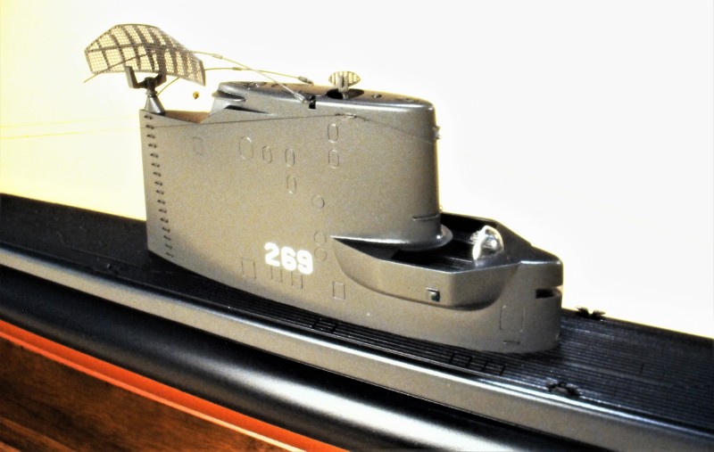
Note the semi-circular clear spray-shield and compass repeater atop and within the open bridge cockpit.
Keep in mind, as you examine this photo, that the entire sail structure is made from three substrates: wood, GRP, and vacuformed polystyrene. Looks like one large organic structure doesn't it? The wonders of filler, putty, sandpaper, plenty of elbow-grease, primer, and paint on display here.
THIS is model building! Not something pooped out from the back-side of a Star Trek Replicator.
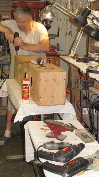
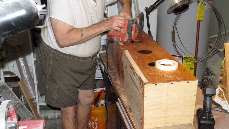
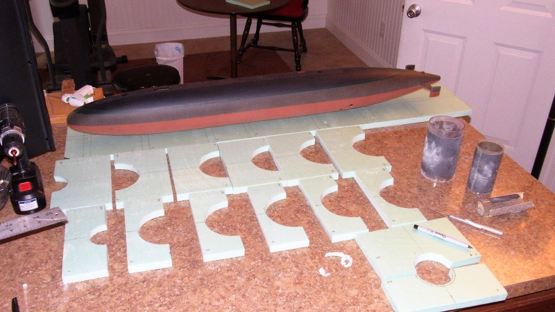
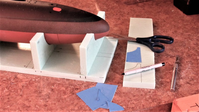
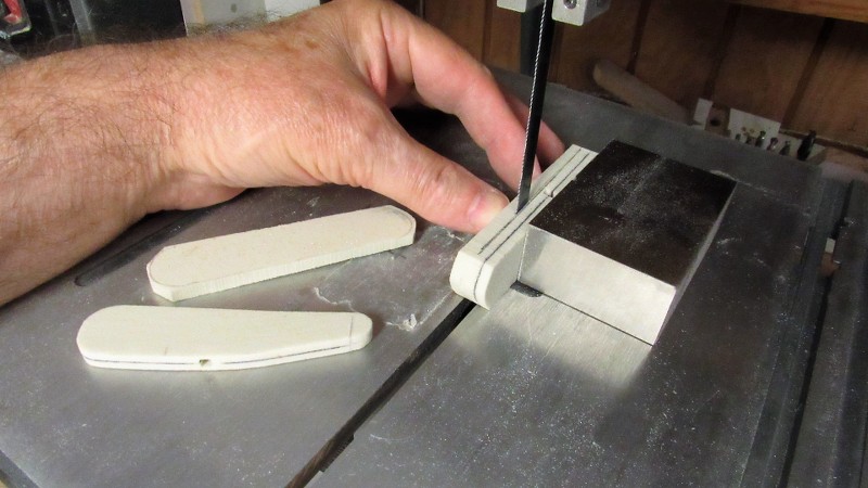
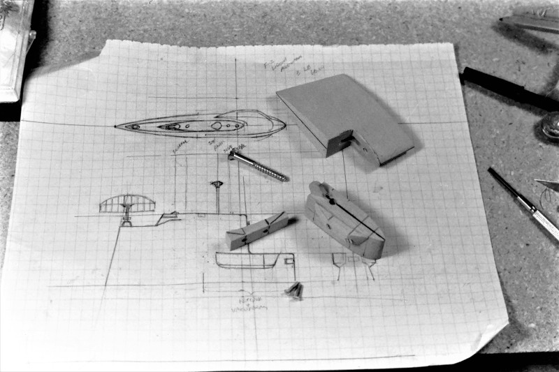
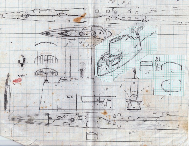
First, I prepared a scale three-view shop sketch of the proposed sail structure. Study of that drawing informed me as to where to employ wood, vacuformed polystyrene, and GRP.
Two slabs of pattern making wood (kiln dried and well seasoned Basswood -- these were the days before RenShape) were epoxied together, after first tinting the glue black. This produced a well defined centerline along the length of this sail blank, no matter how it was sawed, filed and sanded; the master would always present a dark centerline at all edges; that reference plane assuring symmetry between port and starboard halves as I worked the basic sail piece to shape.
However, before joining the two halves of the sail blank I laid down a square of wax paper between the halves where the eventual bridge structure would be -- I would later remove that portion of the sail and then split it along the glue plane. The wax paper made that task an easy one.
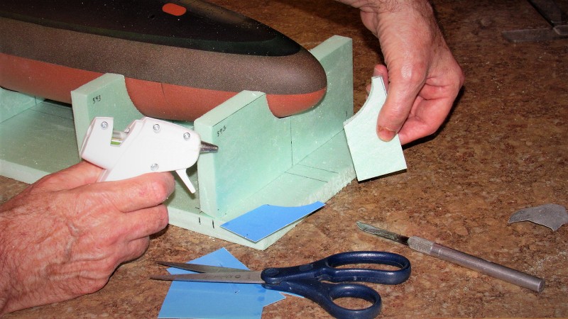
Once the glue had cured hard I razor sawed off the top of the sail -- later using that piece as a pattern for vacuforming. The forward lower corner of the wooden sail was cut away, and a tongue-and-groove indexing system provided to insure exact keying together of the two sub-assemblies.
Working the split bridge master involved extending the bridge cockpit, port and starboard, with more Basswood, those pieces screwed (and later glued) in place to the sides of the bridge master. I periodically assembled the bridge to the sail to insure a smooth transition at their mating points.
You see, to good advantage here, the dark centerline plane left by the darkened epoxy.
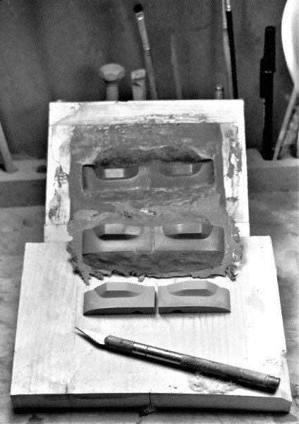
The eventual GRP bridge structure would be laid up within a hard-shell GRP tool (mold). Here I've separated the bridge master into halves and mounted them on a mold board.
The face of the mold board and masters were first waxed then given several coats of polyvinyl alcohol (PVA). These agents producing a barrier -- a mold release -- between masters and GRP used to create the tool, keeping the laidup tool from permanently (and tragically) bonding to the master and mold board.
Tool making started with brushing on a well thickened 'gel-coat' of epoxy laminating resin over the patterns and mold board. Once that layer had hardened to a tack-free state I laid on several plys of 10 ounce glass cloth, and saturated the cloth with laminating resin. After a two-day cure I popped the bridge structure tool off the masters and got to work laying up the GRP bridge structure halves.
In background is the hard-shell bridge structure tool. Mid-ground is a raw test lay-up as it looked straight out of the tool. And foreground is a trimmed set of bridge structure GRP parts that will eventually be assembled and installed to the leading edge of the wooden sail.
The completed GRP bridge structure about to be bonded to the wooden sail.
Illustrating the use of Bondo filler, Nitro-Stan air-dry putty, CA, and primer -- all employed to attach and fair in the GRP bridge structure to the wooden sail structure. Looks like hell here, but a few squirts of gray primer and it all comes together, seamlessly!
When all the smoke clears, this is the result.
Damn!... I'm good.
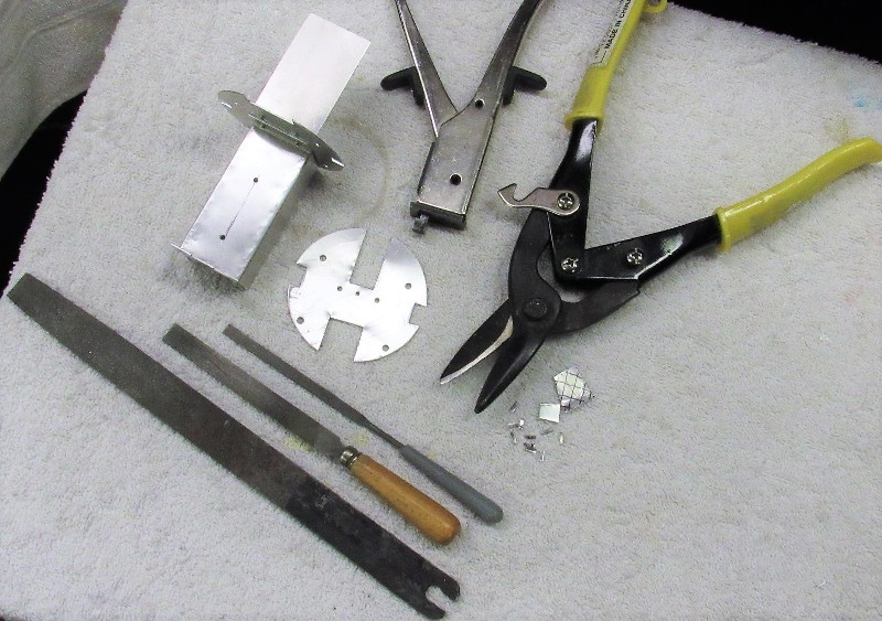
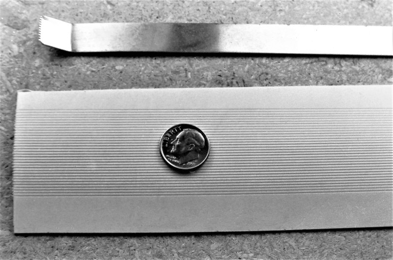
METAL WORK
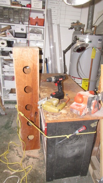
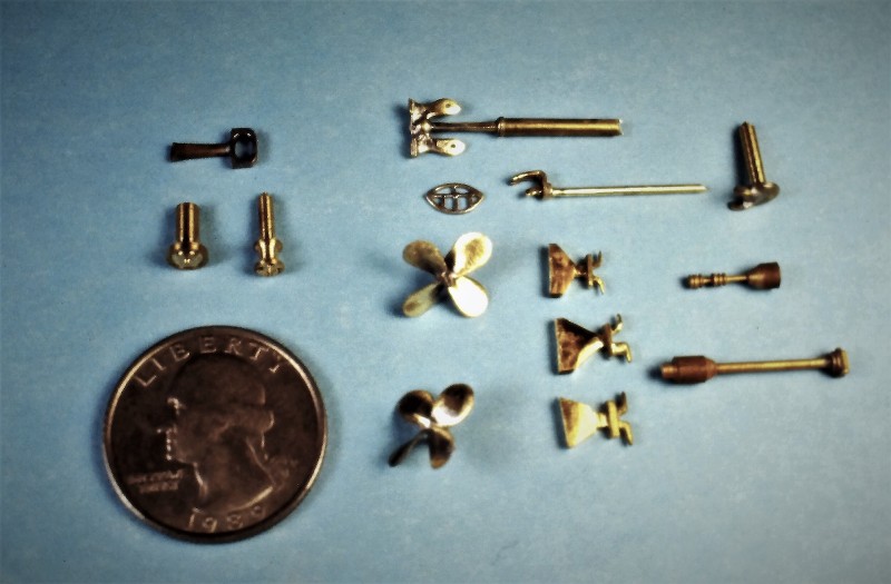
At the time we took the RASHER commission it was assumed there would be more former boat sailors looking for models of submarines they had served on. That hope drove my methodology of part fabrication to employ techniques that would give us the ability to quickly produce museum quality display pieces based on the 1/180 scale Revell LIONFISH kit. That meant producing masters, mostly from brass, from which a spin-casting rubber tool would be made; that tool used to cast white-metal parts quickly, accurately, and in mass. The same logic drove me to embrace the vacuforming and GRP processes for the larger fittings that had to be of thin wall thickness.
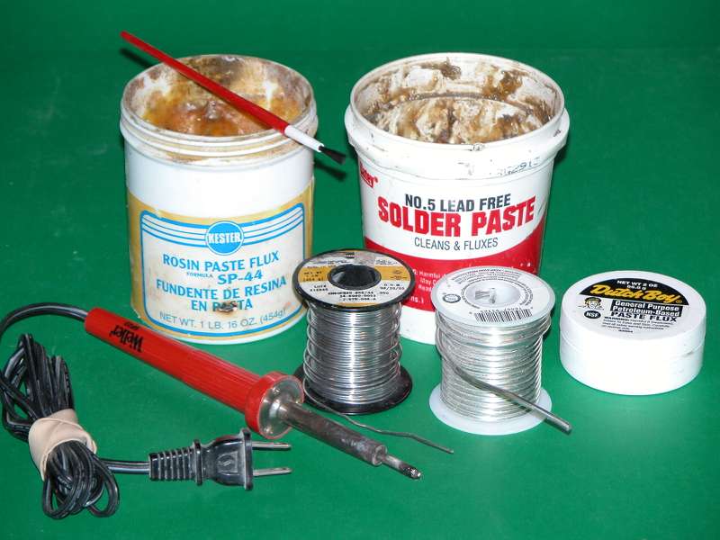
Most the metal masters are shown below: The propellers, anchor, small radar reflector and hatch were solder projects; the capstan, snorkel induction head-valve, small radar stem, hatch, gyro-compass repeater, and UHF antenna were turned on our watch-makers lathe.
The closed chock, anchor foot and flukes, and three fixed cleats were drilled, ground, and filed by hand from thick brass sheet. The Revell LIONFISH propellers were terrible and had to be replaced.
Soldering is to metal what adhesives are to non-metallic substrates. Look on solder as an adhesive like hot-glue. It's not a weld, or fusion process. Soldering is an adhesive. The trick is to abrade the work free of all grease, oil, and oxidation and to employ flux to insure a proper 'wetting' of the metal surfaces as the solder flows into the union gaps. The mechanism of 'stick' is atomic attraction, not fusion. Solder is glue!
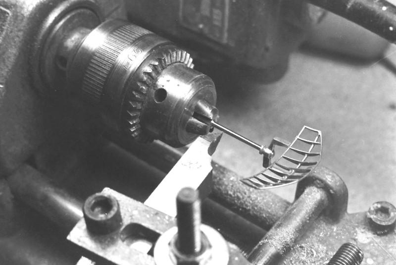
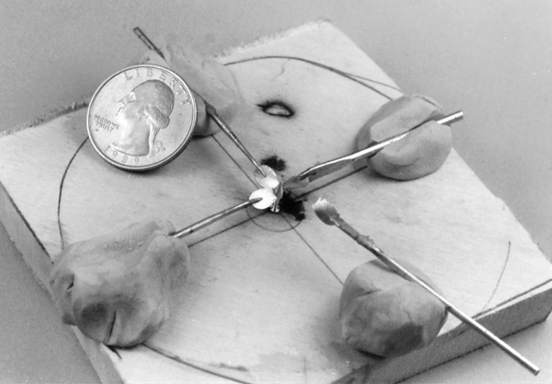
A few pieces of brass round and sheet stock, some solder, and clever use of assembly jigs and you have the big BPS-2 radar that sits atop the RASHER's sail. Later an acid-etched reflector screen would be glued to the concave side of the parabolic framework.
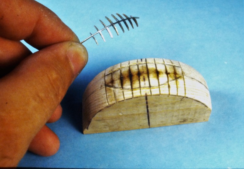
A wooden jig was used to hold the eight vertical radar reflector ribs in correct alignment as a bent central horizontal stringer was soldered within a slot in the middle of each rib. The part was then pulled away from the jig and readied to receive a soldered stringer along the tips of the ribs.
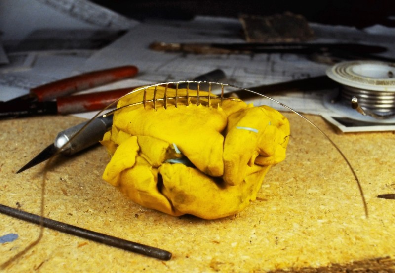
The still rather flimsy structure of the reflector framework was held in a lump of clay, and a bent brass wire solder to the tips of the ribs. The reflector framework was then removed from the clay, cleaned with brush and lacquer thinner, then turned upside-down, re-mounted in the clay, and another length of brass wire soldered to the tip of the rubs. Excess wire was snipped away and careful work with files removed excess solder from the work.
Cleaned up and slathered with flux the radar reflector framework was soldered to a brass wave-guide horn assembly.
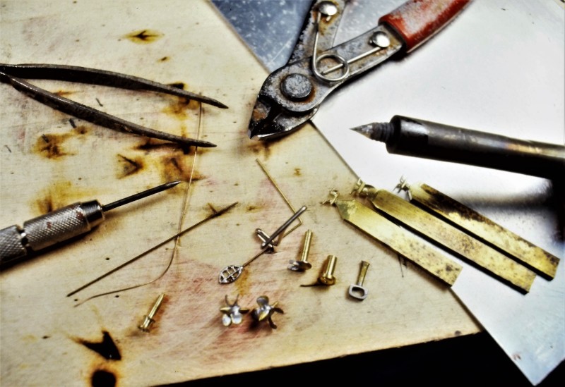
An assembly jig was used to position the acid-etched propeller blades to a turned brass hub. Once all four blades were in position the joints were slathered with flux. The wooden jig was then soaked in water to keep it from catching fire. A very small shard of solder was placed atop each blade where it met the hub (the sticky flux holding each shard of solder where you wanted it). With all five brass parts in perfect alignment the flame of a small hand-torch was played over the work till the soldered melted and flowed to fill all joints.
Ladder rungs that ran up the trailing edge of the sail were bent from .014" brass wire and inserted into holes. No need to glue them as they extended deep enough into the wood to insure a good and tight interference fit.
(You just have to imagine some white-hat idiot climbing up to the BPS-2 radar as the boat bounced around in a state-3 sea... at night... without a safety-harness... in the middle of Winter!).
Brass and white metal, if not prepared, will not permit putties, primers or paints to adhere with any meaningful strength. To make these substrates more attractive to adhesives and paints is to 'pickle' them in an acid like Ferric chloride or vinegar. The acid quickly oxidizes the metals surface produce zillions of microscope pits. This substantially increases the surface area of the metal part and also produces the 'tooth' needed to mechanically hold the adhesive/filler/putty/primer/paint firmly.
The example below shows three white metal cleats. The bright shiny one in foreground is virgin.
The dark gray cleat next to it has been pickled then rubbed down enough to remove the oxide layer, but not abraded enough to obliterate the pitted surface. It's ready for gluing and primer.
The black cleat over the acid is being scrubbed with an 'acid-brush' to accelerate the acid attack. A quick dunking in fresh water, spiked with a bit of baking soda, is enough to kill the acid. The part is then dried with a soft cloth.
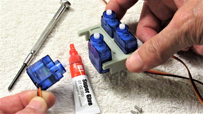
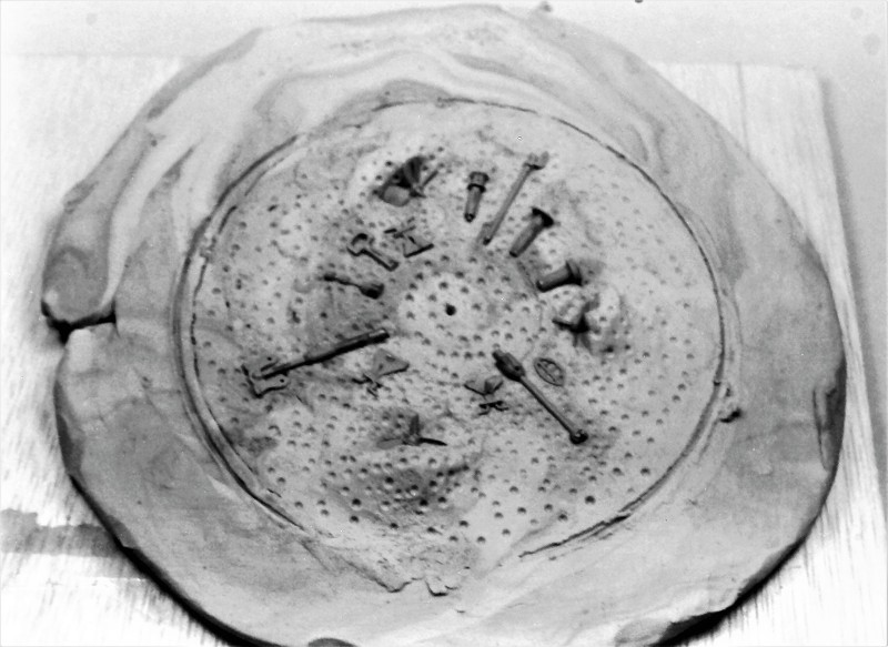
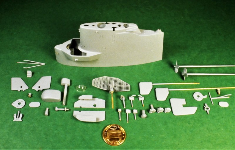
METAL CASTING
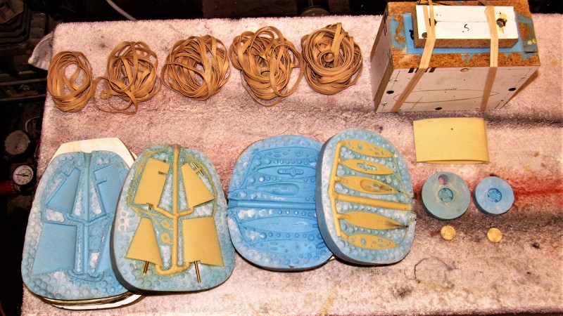
I elected to render all of the small bits as white-metal castings -- I expected that I would be tasked with assembling other 1/180 scale GATO/BALAO/TENCH class display pieces so I wanted the ability to make these small, fiddly pieces quickly, and in mass. However, as it turned out, after over thirty-years, the RASHER is the only display we've been commissioned to build to that particular scale. Here you can see a fret fresh out of the spin-casting tool next to cast metal parts all cleaned up and ready for pickling.
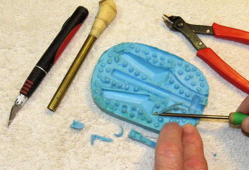
Creating the spin-casting, two-piece rubber tool starts with sinking the masters into a clay mask, its job to permit the first pour of the tool to only encapsulate approximately half of each master. Later, a second pour of rubber would be poured to create the other half of the tool.
Centrifugal force is the agent that immediately pushes the molten metal from the central sprue, down into the cavities of the tool that give shape to each metal part. Note the many dimples pushed into the masking clay. They will become positive registration nipples in the first half of the rubber tool, which in turn will produce registration dimples as the second rubber tool half is poured over the first.
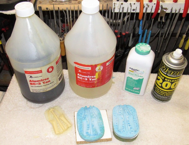
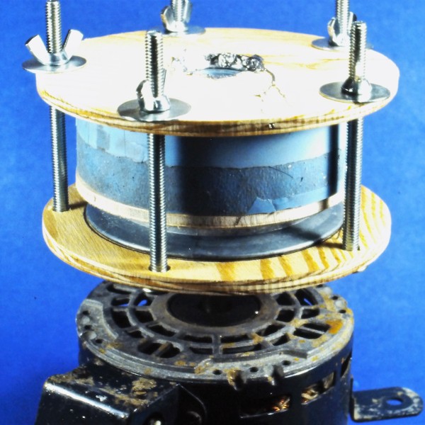
The completed two-piece spin-casting rubber tool and a test shot below the tool halves.
The actual casting process goes quickly: molten white-metal -- 95% Tin, 5% Antimony -- is poured into the central sprue of the upper tool half while the entire tool is sent spinning at a considerable speed. Centrifugal force immediately drives the liquid metal outward, completely filling all cavities within the tool.
Ellie and I registered our business, D&E Miniatures, sometime in the late-70's. We became a proper business at that point and carried on with our work of manufacturing and selling small display and commemorative models to individuals and institutions. That move put us on the map and secured a tax exempt number.
Other than that, becoming a sole proprietary business made little difference to our day to day activities: I was still in the Navy, Ellie was wrangling two Alpha teenagers and worked at Electric Boats 'canteen', and we built models for money on the side.
Time had come to step up the business, so we chummed the waters. A brochure listing our services was prepared and hundreds of them were mailed out -- mostly to big industrial players, movie studios (though the studio system was crumbling then, I reasoned that there might still be some meat on those bones), schools of Engineering (those with tow tanks and/or wind tunnels), a few shipyards, NASCAR sponsors, airlines, and cruise lines. In those days, before the Internet, the connective tissue between businesses was the big, green Thomas Register books. Within those pages we found our target audience.
And, damned if that didn't work!
In no time we began to be wooed by members of the defense industry. Models to be displayed at the many trade shows such businesses attended domestically and abroad. We soon found that working for people who promoted and fostered, 'man's greatest outdoor activity' was good money. No big surprise to me, but a bit of a culture-shock for Ellie to learn that those who make, promote, and sell weapons of war, and their vendors, make a good living.
One of my duty-stations was the dive-locker aboard the destroyer tender, USS VULCAN. I spent my entire four years working the ships tied up at the Naval Base, Norfolk. No underway time, no duty-section; a regular day-time job. And those four years I worked at the south end of the base, in a double-wide tailor with the other VULCAN divers. I pulling down base-pay, dive-pay, and sea-pay! During the day a ships husbandry diver; by night and weekends, back at home, Ellie and I were busy building models for The Lords of War. Life was good!
We built a lot of 'interesting' models for the defense trade. On occasion a client would put the two of us up at the convention site to baby-sit the display pieces; to be on hand if the models needed moving or repair. Someone snapped this shot of us at one of the D.C. Navy League sponsored defense conventions as we took a breather in the clients 'hospitality suite'.
Typically, the division of labor went like this: Ellie did the production work and screened inquiries. I did the research, layout, masters, tools, and detail stuff. That put the RASHER job firmly in my court.
But, though we were kept busy with the defense clients, I did accept the occasion commission from private individuals. Which was the case with the subject presented here: a 1/180 scale, highly detailed model of the USS RASHER, SSR 269. The client sent me a stack of photos and his suggestion that I work up the display using the then available Revell LIONFISH plastic model kit.
The RASHER and her sisters were WW-2 era GATO class diesel boats modified to serve as radar picket submarine -- advance scouts for fleet battle groups. Hence the new designation SSR. The Migraine-3 program defined and oversaw the modification. The Migraine-3 boats, of which the RASHER was a member, were extensively reworked. They were lengthened, their stern tubes removed to make room for the increased compliment, huge air-search radars installed atop their GUPPY like sails, and a dedicated air-control center installed to coordinate friendly air operations as well as presenting the tactical situation to the battle-group Commander. But, the days of the SSR's were brief as AWAC aircraft, satellites, and SSN's quickly took over the roll of battle-group point-man.
DBF.
This picture of RASHER shows her a short time after the Migraine-3 conversion, as the bulbous height-finding radar just abaft the sail and smaller 'homing beacon' radar near the turtle-back are still in place. These items were soon removed leaving only the big sail mounted BPS-2 radar antenna to tell the world that RASHER was a radar picket submarine.
The projecting bridge 'wings' permitted the conning officer and lookouts to get a view aft without their line of sight being to badly blocked by the elongated sail.
(My apologies for the grainy quality of the following in-work and beauty shots that chronicle creation of the RASHER display. I documented this work in the late 80's, before I embraced digital photography. The pictures that follow were recently copied digitally from the original, and slightly time diminished, color slide positive film and black & white negative film I've retained through the years).


Three major tasks presented themselves as I converted the LIONFISH kit to the Migraine-3 RASHER: Lengthen the hull and capture the 'knuckle' where the forward end of the hull extension piece butted up ugly to the rest of the submarines bow; manufacture of an entirely new sail fairwater with its weird bridge wings; and creation of that big BPS-2 drag inducing parachute of a radar antenna mounted atop that sail.
THE HULL
The Migraine-3 boats were lengthened to make room for the CIC space and additional equipment.
To extend the kits hull 25-scale-feet I bought a second LIONFISH kit and grafted a portion of that to the display hull. The graft done at the hulls maximum breadth so as not to spoil the natural curve of the hull. Once the hull was lengthened I would later ugly up the hull at the point near the bow where the hull extension was performed on the actual boat.

Automotive filler -- classified as a thermosetting type plastic -- is a mixture of polyester resin and finally ground, inert 'filler' to thicken the product. The catalyzed goo can be applied, in mass, to a surface in need of re-contouring without fear of sagging. Unlike air-dry putties (like my favorite, Nitro-Stan) that can't be put on too thickly, with a catalyzed filler the thicker you put it on, the hotter it gets, and the quicker it changes state from semi-liquid to hard mass.
For this discussion I'll use the trade name of a familiar brand of filler: 'Bondo'.
The after end of the extension segment attached at or near the operations compartment forward bulkhead -- a bit forward of the conning tower-fairwater leading edge. This constant diameter extension of the pressure hull, and saddle type ballast tanks that surrounded it, resulted in a nasty looking 'knuckle' at the forward end of the extension. This, of course, ruined the smooth lines of the hull so close to the sharply curving bow. Oh, well... function over beauty, as they say.
I built an external radial frame from .065" thick polystyrene sheet. This external reference frame girdling the hull where the forward end of the hull extension piece was to be. That frame, at its outer edge, having the same geometry as the after end of the supposed extension.
I screeded on catalyzed Bondo to the height of the external frame both fore and aft, feathering the filler to the surface of the hull. With just a few careful passes of a broad bladed putty knife, I had roughed out a credible looking 'knuckle' to the hull lines forward.

Some filing and sanding, a bit more Bondo, more sanding, then Nitro-Stan air-dry touch-up putty to address file and sanding marks, yet more sanding, and the hull was ready for gray primer.
Bondo was also used to fill the concave portions of the bow and stern torpedo tube shutter doors. Also, a bit of Bondo was used to fill the gap between the wooden sail and GRP bridge structure once they were glued together.
A word to the wise: Bondo like fillers are for re-contouring and filling of significant gaps. The Nitro-Stan air-dry lacquer based touch-up putty, on the other hand, is for very shallow gaps and tool-marks.
Don't use hobby-shop sold air-dry putties or paints... they're crap; formulated to be safe, not effective. Green-Stuff and the like, if applied too heavily, will take years to thoroughly harden. Nitro-Stan is much quicker to dry owing to that products extremely volatile solvents.
Hint: If the product labeling does not warn of cancer, warts, lung damage, distemper, Ebola, or your dick falling off, the stuff is useless! The good stuff -- putties, primers, paint, and clear coat systems -- will be found at automotive supply houses and Ebay.
GLASS REINFORCED PLASTIC (GRP)
fiberglass layup is the process of forming tough, light weight, thin walled structures by encapsulating strands of fiberglass with a hardened plastic resin. The resin, once it changes state from liquid to solid, provides the stiffness. The embedded glass strands endows the structure with great strength. Just the right material from which to fabricate the open bridge structure at the leading edge of the sail.
Note the semi-circular clear spray-shield and compass repeater atop and within the open bridge cockpit.
Keep in mind, as you examine this photo, that the entire sail structure is made from three substrates: wood, GRP, and vacuformed polystyrene. Looks like one large organic structure doesn't it? The wonders of filler, putty, sandpaper, plenty of elbow-grease, primer, and paint on display here.
THIS is model building! Not something pooped out from the back-side of a Star Trek Replicator.
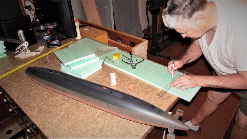
First, I prepared a scale three-view shop sketch of the proposed sail structure. Study of that drawing informed me as to where to employ wood, vacuformed polystyrene, and GRP.
Two slabs of pattern making wood (kiln dried and well seasoned Basswood -- these were the days before RenShape) were epoxied together, after first tinting the glue black. This produced a well defined centerline along the length of this sail blank, no matter how it was sawed, filed and sanded; the master would always present a dark centerline at all edges; that reference plane assuring symmetry between port and starboard halves as I worked the basic sail piece to shape.
However, before joining the two halves of the sail blank I laid down a square of wax paper between the halves where the eventual bridge structure would be -- I would later remove that portion of the sail and then split it along the glue plane. The wax paper made that task an easy one.

Once the glue had cured hard I razor sawed off the top of the sail -- later using that piece as a pattern for vacuforming. The forward lower corner of the wooden sail was cut away, and a tongue-and-groove indexing system provided to insure exact keying together of the two sub-assemblies.
Working the split bridge master involved extending the bridge cockpit, port and starboard, with more Basswood, those pieces screwed (and later glued) in place to the sides of the bridge master. I periodically assembled the bridge to the sail to insure a smooth transition at their mating points.
You see, to good advantage here, the dark centerline plane left by the darkened epoxy.
The eventual GRP bridge structure would be laid up within a hard-shell GRP tool (mold). Here I've separated the bridge master into halves and mounted them on a mold board.
The face of the mold board and masters were first waxed then given several coats of polyvinyl alcohol (PVA). These agents producing a barrier -- a mold release -- between masters and GRP used to create the tool, keeping the laidup tool from permanently (and tragically) bonding to the master and mold board.
Tool making started with brushing on a well thickened 'gel-coat' of epoxy laminating resin over the patterns and mold board. Once that layer had hardened to a tack-free state I laid on several plys of 10 ounce glass cloth, and saturated the cloth with laminating resin. After a two-day cure I popped the bridge structure tool off the masters and got to work laying up the GRP bridge structure halves.

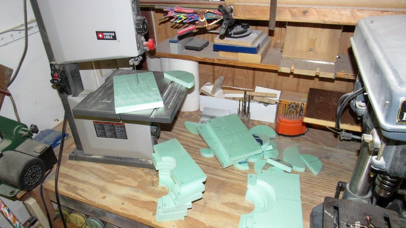
In background is the hard-shell bridge structure tool. Mid-ground is a raw test lay-up as it looked straight out of the tool. And foreground is a trimmed set of bridge structure GRP parts that will eventually be assembled and installed to the leading edge of the wooden sail.
The completed GRP bridge structure about to be bonded to the wooden sail.
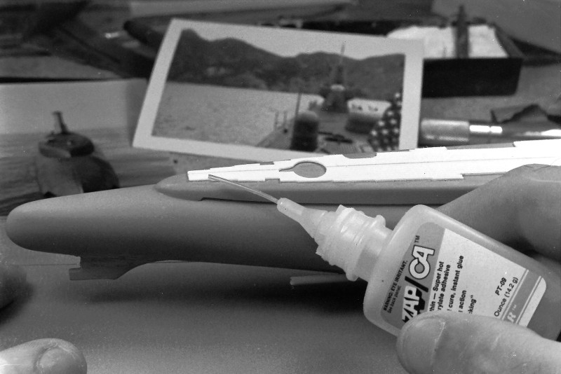
Illustrating the use of Bondo filler, Nitro-Stan air-dry putty, CA, and primer -- all employed to attach and fair in the GRP bridge structure to the wooden sail structure. Looks like hell here, but a few squirts of gray primer and it all comes together, seamlessly!

When all the smoke clears, this is the result.
Damn!... I'm good.
METAL WORK
At the time we took the RASHER commission it was assumed there would be more former boat sailors looking for models of submarines they had served on. That hope drove my methodology of part fabrication to employ techniques that would give us the ability to quickly produce museum quality display pieces based on the 1/180 scale Revell LIONFISH kit. That meant producing masters, mostly from brass, from which a spin-casting rubber tool would be made; that tool used to cast white-metal parts quickly, accurately, and in mass. The same logic drove me to embrace the vacuforming and GRP processes for the larger fittings that had to be of thin wall thickness.
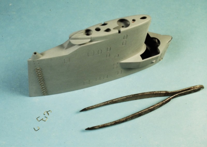
Most the metal masters are shown below: The propellers, anchor, small radar reflector and hatch were solder projects; the capstan, snorkel induction head-valve, small radar stem, hatch, gyro-compass repeater, and UHF antenna were turned on our watch-makers lathe.
The closed chock, anchor foot and flukes, and three fixed cleats were drilled, ground, and filed by hand from thick brass sheet. The Revell LIONFISH propellers were terrible and had to be replaced.
Soldering is to metal what adhesives are to non-metallic substrates. Look on solder as an adhesive like hot-glue. It's not a weld, or fusion process. Soldering is an adhesive. The trick is to abrade the work free of all grease, oil, and oxidation and to employ flux to insure a proper 'wetting' of the metal surfaces as the solder flows into the union gaps. The mechanism of 'stick' is atomic attraction, not fusion. Solder is glue!
A few pieces of brass round and sheet stock, some solder, and clever use of assembly jigs and you have the big BPS-2 radar that sits atop the RASHER's sail. Later an acid-etched reflector screen would be glued to the concave side of the parabolic framework.
A wooden jig was used to hold the eight vertical radar reflector ribs in correct alignment as a bent central horizontal stringer was soldered within a slot in the middle of each rib. The part was then pulled away from the jig and readied to receive a soldered stringer along the tips of the ribs.
The still rather flimsy structure of the reflector framework was held in a lump of clay, and a bent brass wire solder to the tips of the ribs. The reflector framework was then removed from the clay, cleaned with brush and lacquer thinner, then turned upside-down, re-mounted in the clay, and another length of brass wire soldered to the tip of the rubs. Excess wire was snipped away and careful work with files removed excess solder from the work.
Cleaned up and slathered with flux the radar reflector framework was soldered to a brass wave-guide horn assembly.
An assembly jig was used to position the acid-etched propeller blades to a turned brass hub. Once all four blades were in position the joints were slathered with flux. The wooden jig was then soaked in water to keep it from catching fire. A very small shard of solder was placed atop each blade where it met the hub (the sticky flux holding each shard of solder where you wanted it). With all five brass parts in perfect alignment the flame of a small hand-torch was played over the work till the soldered melted and flowed to fill all joints.
Ladder rungs that ran up the trailing edge of the sail were bent from .014" brass wire and inserted into holes. No need to glue them as they extended deep enough into the wood to insure a good and tight interference fit.
(You just have to imagine some white-hat idiot climbing up to the BPS-2 radar as the boat bounced around in a state-3 sea... at night... without a safety-harness... in the middle of Winter!).
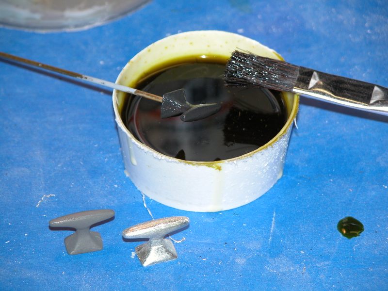
Brass and white metal, if not prepared, will not permit putties, primers or paints to adhere with any meaningful strength. To make these substrates more attractive to adhesives and paints is to 'pickle' them in an acid like Ferric chloride or vinegar. The acid quickly oxidizes the metals surface produce zillions of microscope pits. This substantially increases the surface area of the metal part and also produces the 'tooth' needed to mechanically hold the adhesive/filler/putty/primer/paint firmly.
The example below shows three white metal cleats. The bright shiny one in foreground is virgin.
The dark gray cleat next to it has been pickled then rubbed down enough to remove the oxide layer, but not abraded enough to obliterate the pitted surface. It's ready for gluing and primer.
The black cleat over the acid is being scrubbed with an 'acid-brush' to accelerate the acid attack. A quick dunking in fresh water, spiked with a bit of baking soda, is enough to kill the acid. The part is then dried with a soft cloth.
METAL CASTING
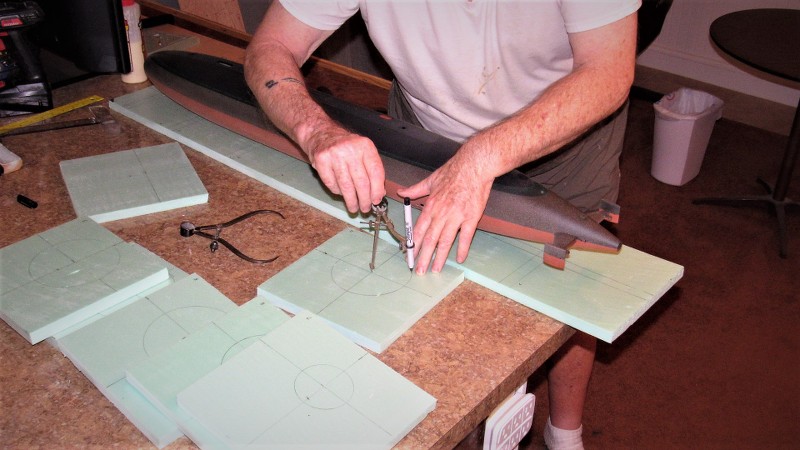
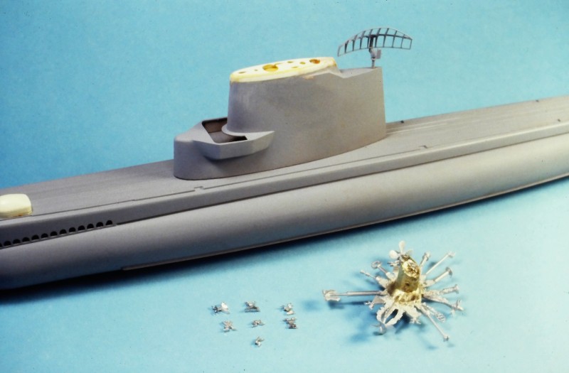
I elected to render all of the small bits as white-metal castings -- I expected that I would be tasked with assembling other 1/180 scale GATO/BALAO/TENCH class display pieces so I wanted the ability to make these small, fiddly pieces quickly, and in mass. However, as it turned out, after over thirty-years, the RASHER is the only display we've been commissioned to build to that particular scale. Here you can see a fret fresh out of the spin-casting tool next to cast metal parts all cleaned up and ready for pickling.
Creating the spin-casting, two-piece rubber tool starts with sinking the masters into a clay mask, its job to permit the first pour of the tool to only encapsulate approximately half of each master. Later, a second pour of rubber would be poured to create the other half of the tool.
Centrifugal force is the agent that immediately pushes the molten metal from the central sprue, down into the cavities of the tool that give shape to each metal part. Note the many dimples pushed into the masking clay. They will become positive registration nipples in the first half of the rubber tool, which in turn will produce registration dimples as the second rubber tool half is poured over the first.
The completed two-piece spin-casting rubber tool and a test shot below the tool halves.

The actual casting process goes quickly: molten white-metal -- 95% Tin, 5% Antimony -- is poured into the central sprue of the upper tool half while the entire tool is sent spinning at a considerable speed. Centrifugal force immediately drives the liquid metal outward, completely filling all cavities within the tool.
- Joined
- 18 March 2013
- Messages
- 978
- Reaction score
- 2,851
VACUFORMING
In this discussion I'm talking about giving permanent shape to heated plastic sheet, forcing it to a specific shape, that shape retained once the plastic cools back to room temperature.
For us, a thermoplastic is that category of plastic that can be heated to a pliable state and then forced, either over a plug/puck/master/pattern/form/whateveryouwanttocallit or into a mold through mechanical or creating a differential pressure between the two faces of the heated plastic sheet.
A very useful technique for the modeler who is looking for a light-weight, thin walled structure that can be rendered in multiples very quickly.
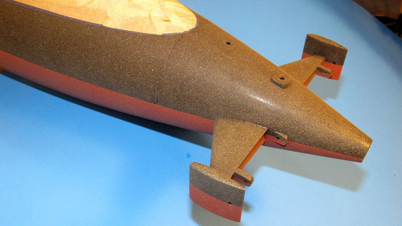
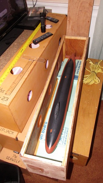
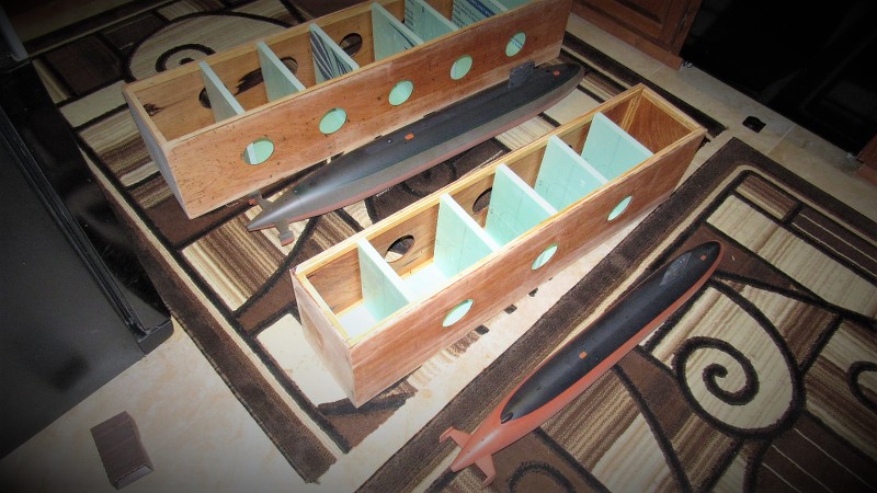
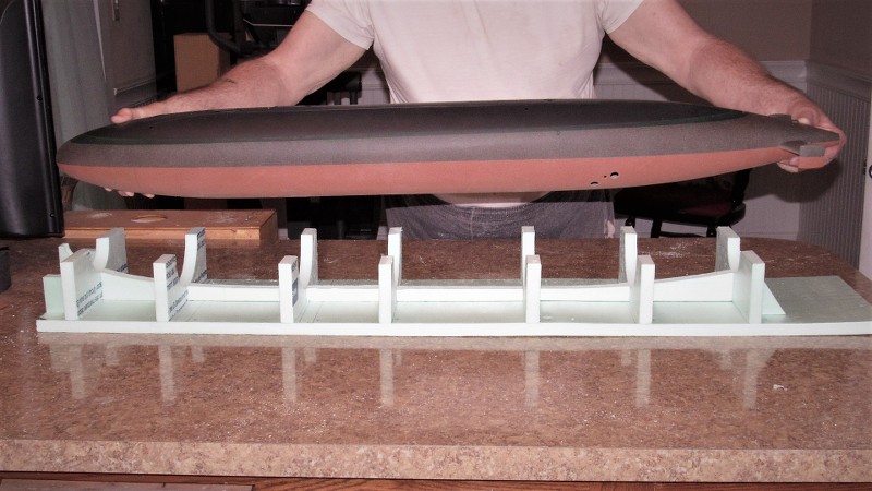
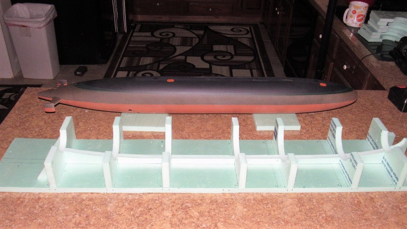
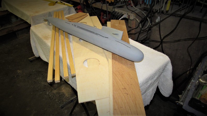
Examine the picture below. The white structure at the bow and the top of the sail are vacuformed items specifically made for this project. Note that the thin walled top-of-sail -- once opening for the retractable masts are punched out -- presents a scale like wall thickness to the edges of those penetrations.
(Many different substrates comprised this model: The polystyrene kit hull; wooden sail, GRP bridge structure at the leading edge of the sail; the huge soldered brass BPS-2 air-search radar; Bondo filled torpedo troughs and hull extension 'knuckle'; and spin-cast white metal detail items.)
The 1/180 scale LIONFISH kits original anchor well was not at all what the RASHER model had, so a vacuformed well was made and grafted into the correct position at the starboard bow. Note the cast white metal anchor just below the anchor well.
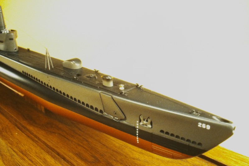
Looking at the completed RASHER display one would never know what a Frankenstein Monster this pieced together model was before primer and paint. Seen to good advantage here are the two deck mounted sonar transducer-hydrophone 'windows' -- both of these items were vacuformed from .060" thick white polystyrene sheet.
If you look to the extreme left of this picture you can make out a vacuformed 'dead-light' (optically clear window) that wrapped around the leading edge of the bridge. On the real boat that was a 'safe' place to hide when green-water came crashing down on you in a state-4 following sea! Aft of that atop the open bridge you can see the extendable bridge 'spray-shield'. Another vacuformed item pulled from clear plastic sheet.
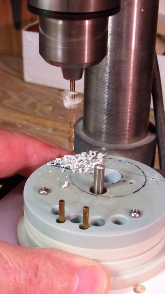
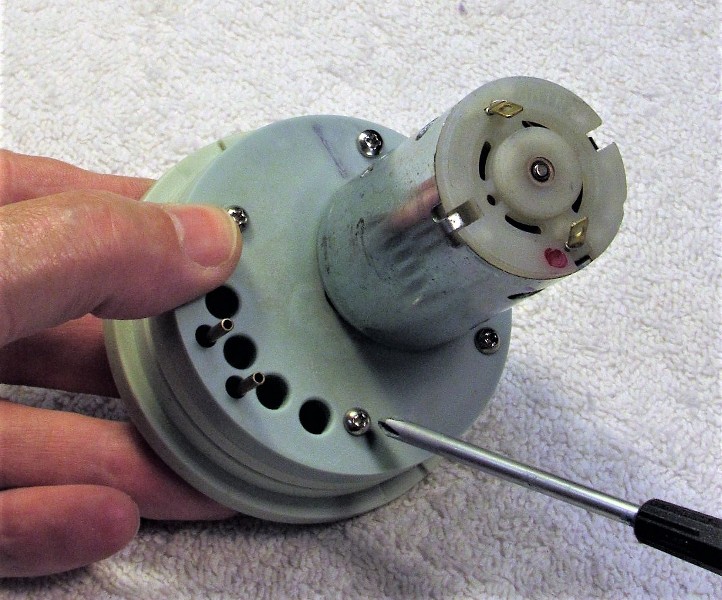
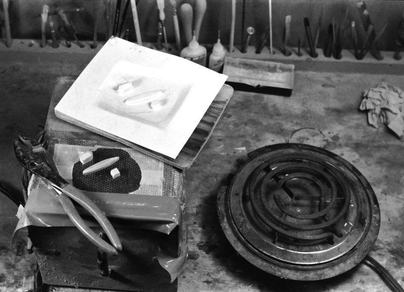
Vacuforming over a pattern simply involves placing the pattern over a plenum whose surface is suitably perforated to extract air from between the pattern and heated plastic sheet. A partial vacuum underneath the sheet, with normal pressure above it is the agent of force here; a differential pressure is created between the top of the work and its bottom. As air is extracted from underneath, normal air pressure atop pushes the pliable plastic down to conform to the shape of the master underneath.
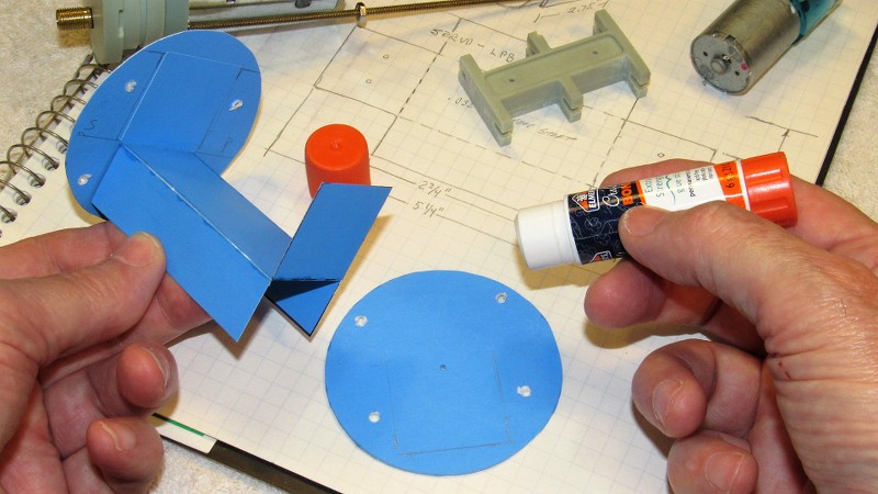
On this particular vacuforming job I used a common electric hot-plate to heat the frame supported plastic sheet. From that one sheet I'll get the top of the sail, and the two bow mounted sonar windows.
Alternative heating sources include torches, as seen here; conviction oven; infrared heat-lamp; and hot-air gun. The vacuum source need not be anything more exotic than the household vacuum-cleaner. In these examples I'm using a discarded Barber's clipper-vacuum (On duty nights, off-watch, I could be found examining dumpster contents at the head of each pier... I was a frig'n raccoon!).
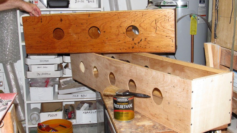
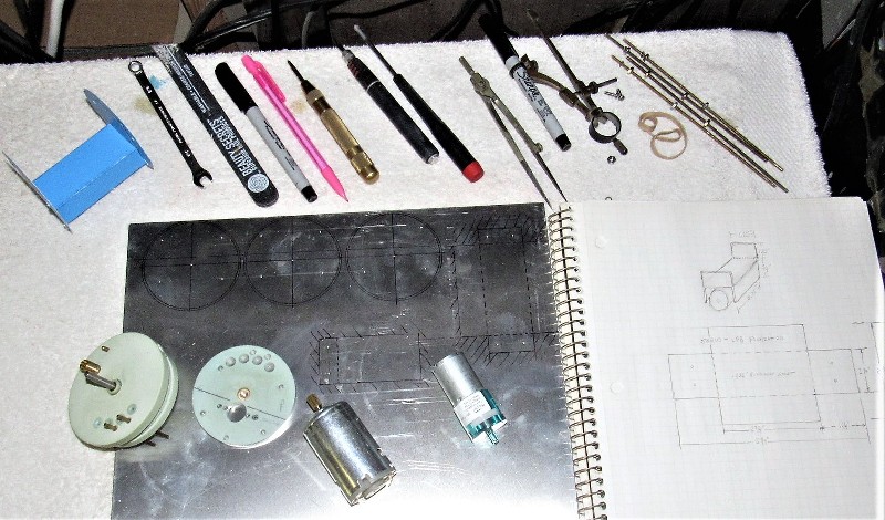
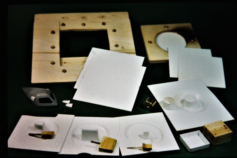
It's imperative to secure the plastic sheet in some sort of holding-frame during the heating process, or the sheet will curl up on you. Here are varied examples of frames, patterns, and vacuformed parts.
The problem with forming the plastic sheet over a pattern is the need to account for the thickness of the plastic sheet, otherwise the vacuformed part will be over sized. This requires under-sizing the pattern to account for this. For surfaces parallel to the plane of the frame its a direct correlation, but for those portions with any draft to them, the wall thickness of the vacuformed part will be a bit less than the original thickness of the sheet. This 'drawing out' is a consequence of the draft angle.
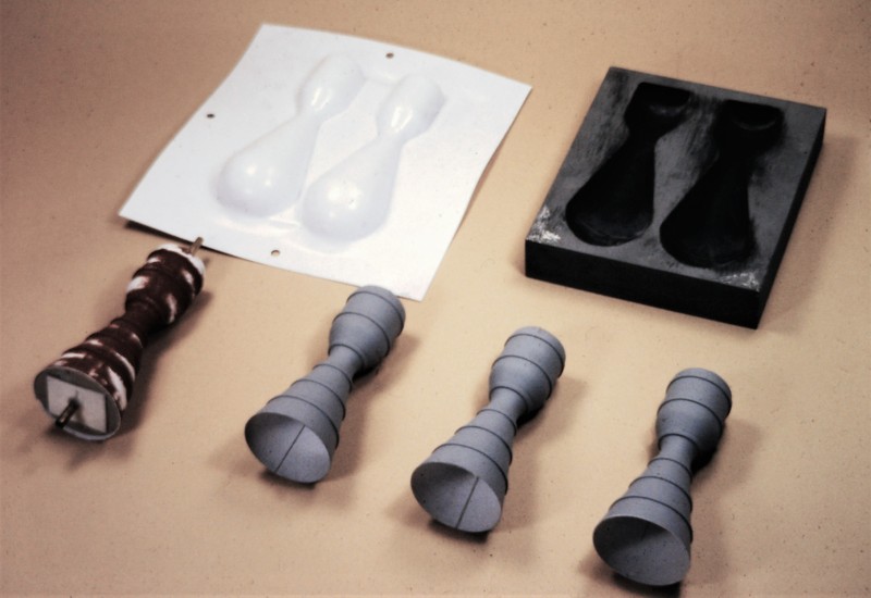
A Vacuforming process that renders exacting surface detail and also captures pattern geometry, requires a temperature tolerant tool, within its cavity(s) is pulled the heated plastic sheet.
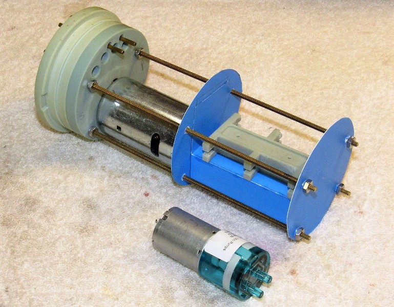
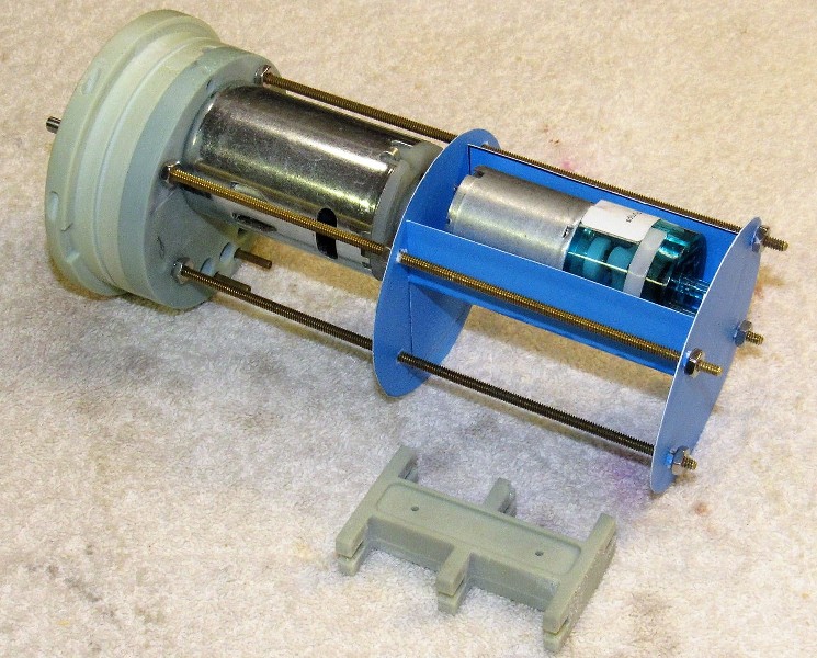
Here, an IBM display we built which required four well detailed rocket motors, made use of a high-temperature mold into which would be pulled heated .080" thick polystyrene sheet. This type tool -- upper right hand corner -- required the drilling of many small vent channels to pull the air out from between the sheet and the cavities of the tool.
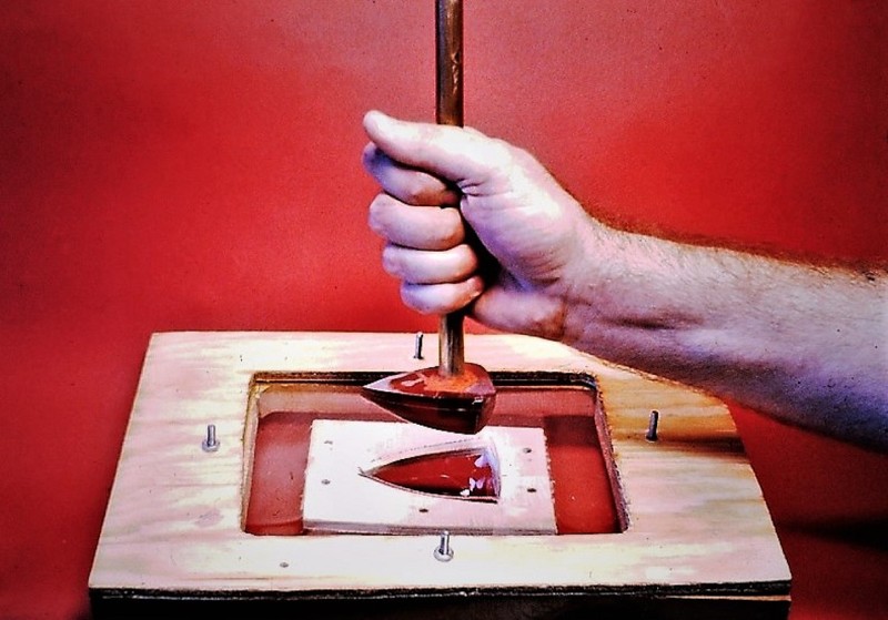
Sometimes it is easier to 'plunge-form' heated plastic like the clear canopy you see here: the pattern is slightly undersized, to account for the wall thickness of the eventual part. After the clear plastic sheet is heated, the pattern is plunged into the sheet. The die, under the sheet, insures a complete wrap-around of the sheet over the pattern. Just another of the many ways one can heat-form a thermoplastic.
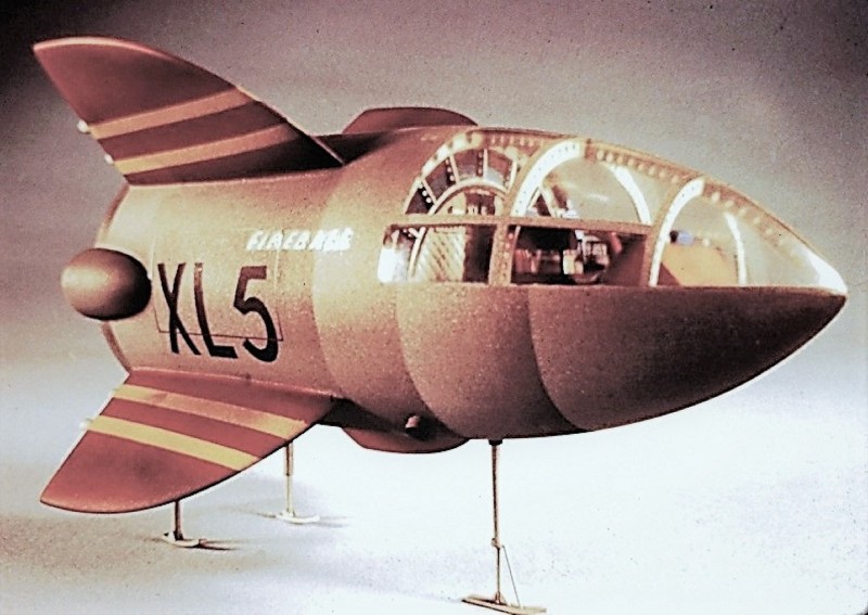
Short of some very heroic-expensive-time consuming casting processes, it's all but impossible to render compound curved clear parts like this wrap-around 'green-house' type canopy plunge-formed for this rather large FIREBALL XL-5 model.
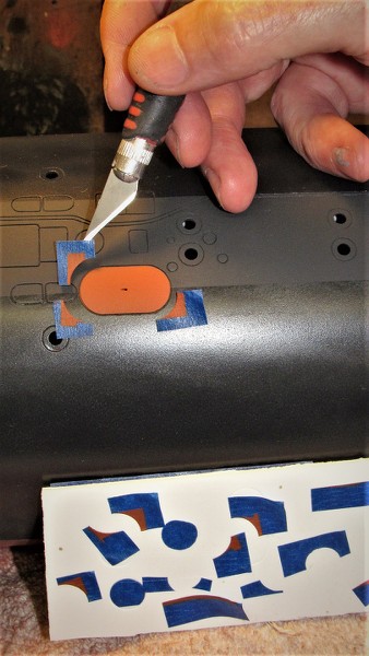
SCRIBING
Scribing is the process of cutting channels into the substrate. These channels of a depth, width, and outline so as to suggest hatch covers, access hand-holes, torpedo tube shutter doors, deck planking, and the like.
Scribing is also employed as the first step in punching holes of complicated outline through thin walled structures, such as the retractable mast holes atop the sail, bow-buoyancy flood-drain openings, and superstructure limber holes.
Scribing is a skill learned by practice. One must become proficient at engraving different types of substrates, be it plastic, wood, GRP, Bondo, or even soft metal.
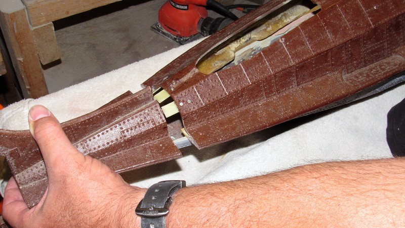
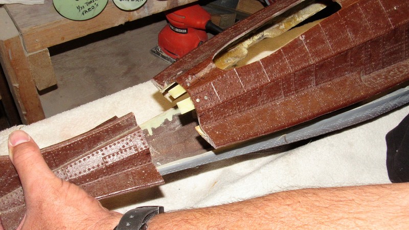
For example, the picture below: The majority of the sail aft of the bridge cockpit is wood, the bridge area is GRP, the top of the sail is vacuformed polystyrene, and the deck is a sheet of polystyrene. Yet all the engraved lines -- no matter the substrate within which they are cut, the engraved lines are of uniform depth and clean of line. If there is any 'art' to model-making, scribing is it!
If a substrate is not receptive to scribing, then you dig out the area to be scribed, back-fill it with Bondo, and scribe that easier to engrave substrate... after putty, sanding, and primer, no one will know the cheat! The hand-holes on the sides of this wooden structure were done this way.
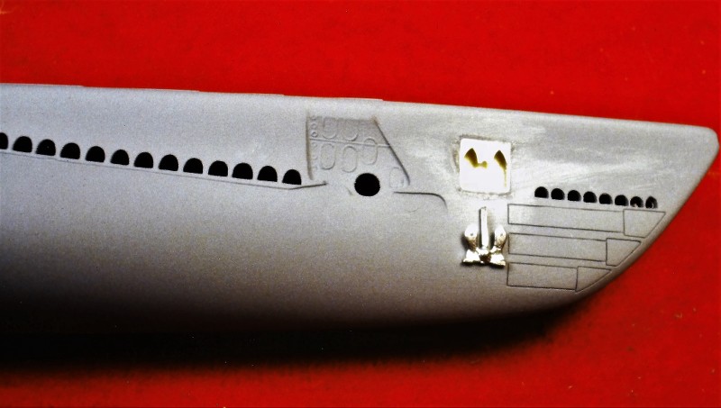
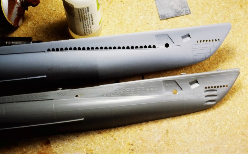
Since we had purchased two of the Revell LIONFISH kits, I took the opportunity to show some before-and-after work. The RASHER hull is above, the raw LIONFISH kit hull is below. Note that the opened up limber holes of the RASHER have a pattern entirely different than the raised limber hole outlines molded onto the sides of the kits superstructure.
Two forms of scribing on display here. The limber holes started out as deeply engraved lines. The shutter doors were engraved after Bondoing and filing flush the shutter door depressions. The RASHER anchor well has yet to be vacuformed and inserted in the correct location just aft of bow-buoyancy.
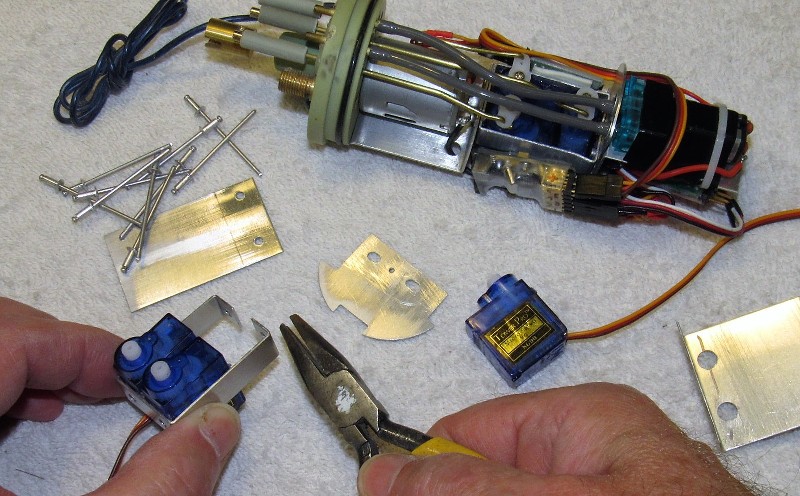
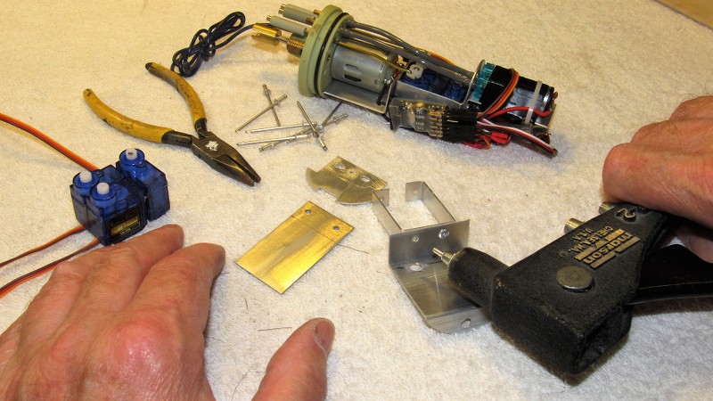
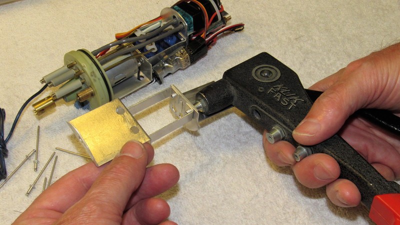
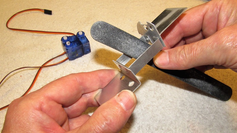
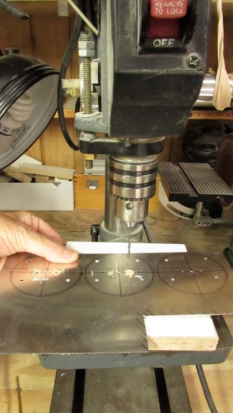
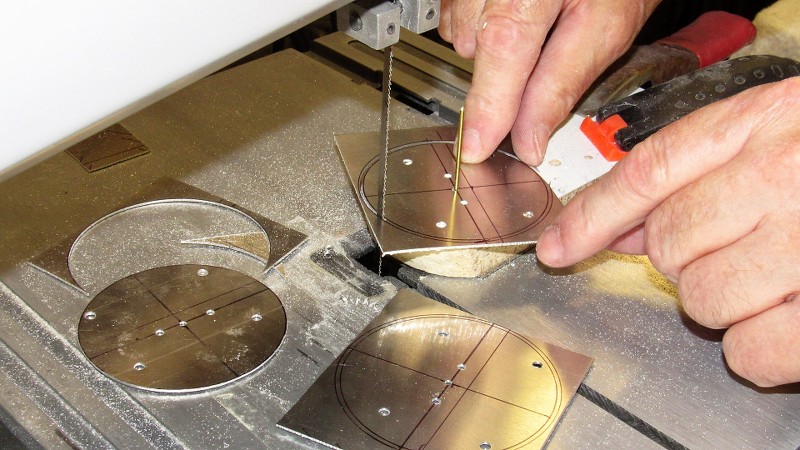
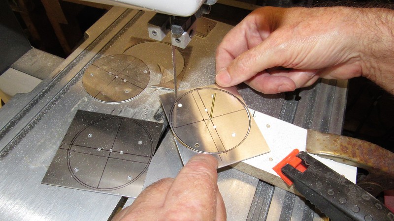
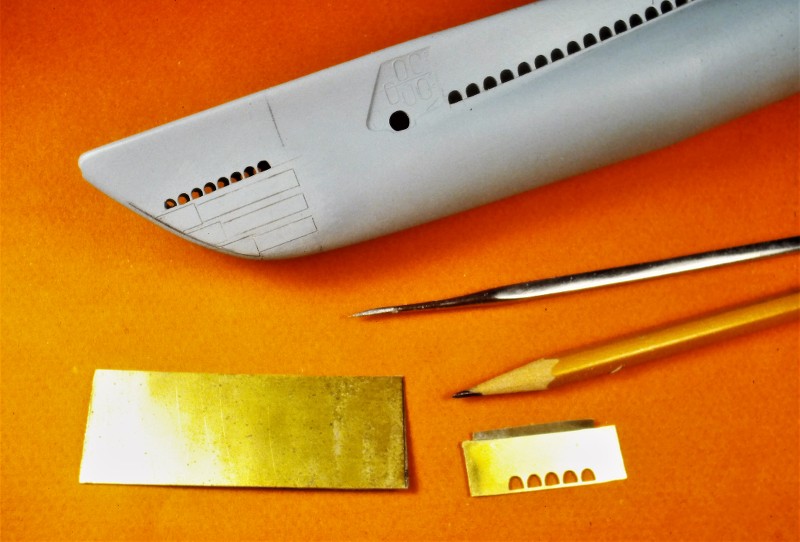
To insure symmetry and proper spacing of the superstructure limber holes I carefully plotted and cut out a set of holes into a .014" thick piece of brass sheet -- this template used to engrave the limber hole outlines onto the soft polystyrene of the kits superstructure. The engraved outlines guided a #11 X-Acto blade as I carefully opened each hole. The work went surprisingly fast.
To keep this limber hole engraving stencil from sliding over the work I glued a piece of sandpaper to the stencils inboard face. A little index finger pressure and the stencil stayed in place as I engraved a set of limber hole outlines onto the superstructure.
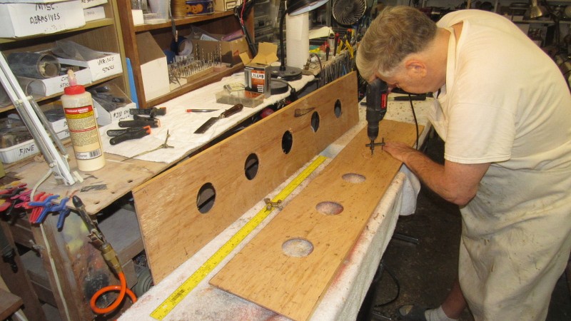
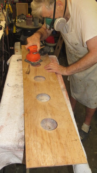
I found that the LIONFISH kits deck in no way represented that of the RASHER. So, I was compelled to produce a scribed deck blank from .040" thick polystyrene sheet.
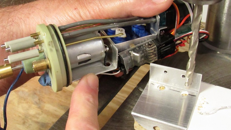
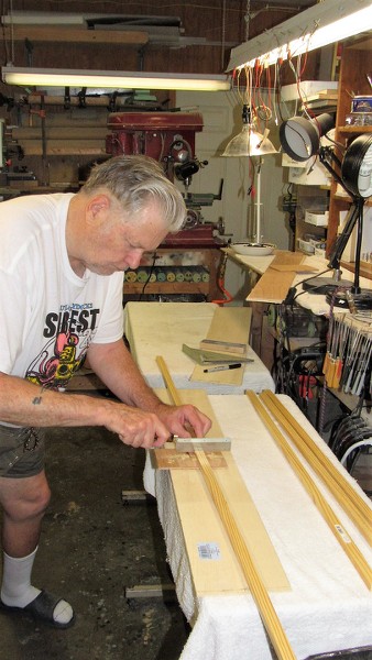
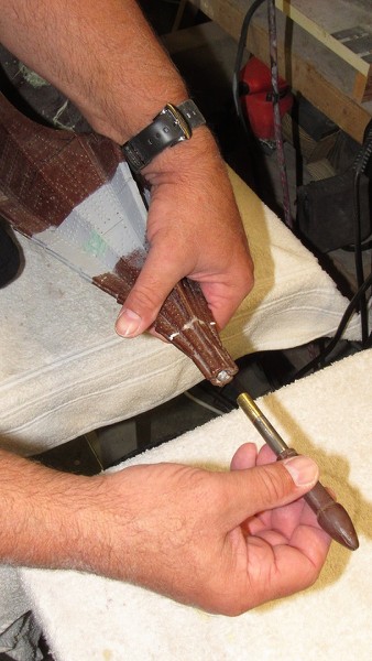
Here I've used a custom made scribing tool to quickly engrave the many parallel lines that give the illusion of well spaced deck planking.
Before gluing the planking down atop the hull I opened up areas that would later receive the two escape trunk escape bell seating surfaces, fixed cleats, muffler access plates, and forward escape trunk side hatch well. After gluing the decking atop the hull it was further scribed to represent the many line and access hatches.
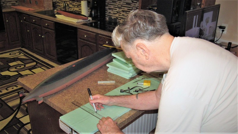
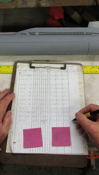
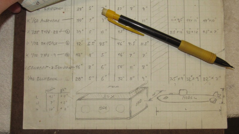
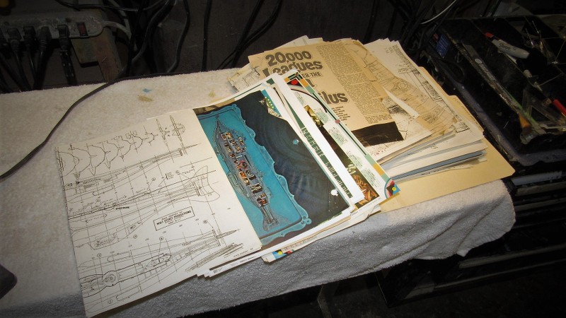
A to-scale shop sketch I developed from my files. Used to guide me during the deck, superstructure, hull, and sail scribing.
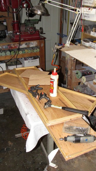
Holy shit!!!!... is that 35 year old blood?
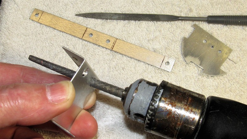
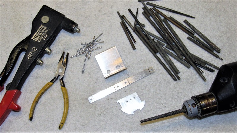
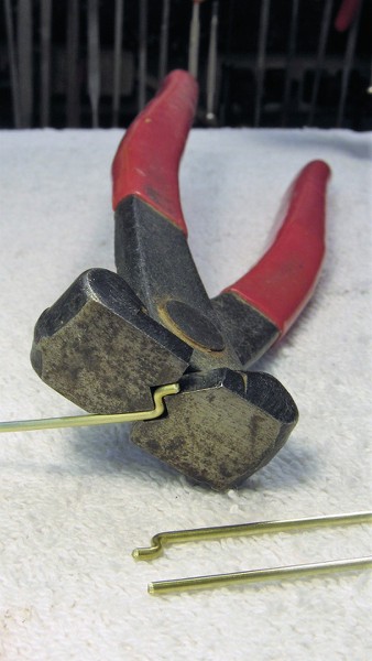
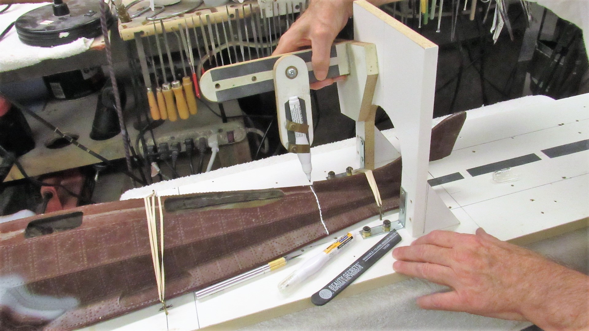
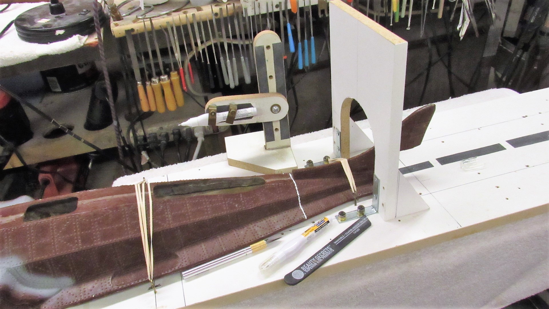
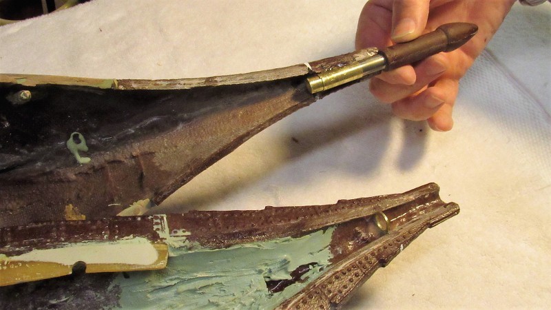
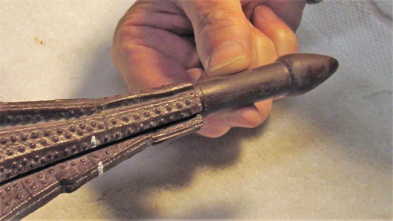
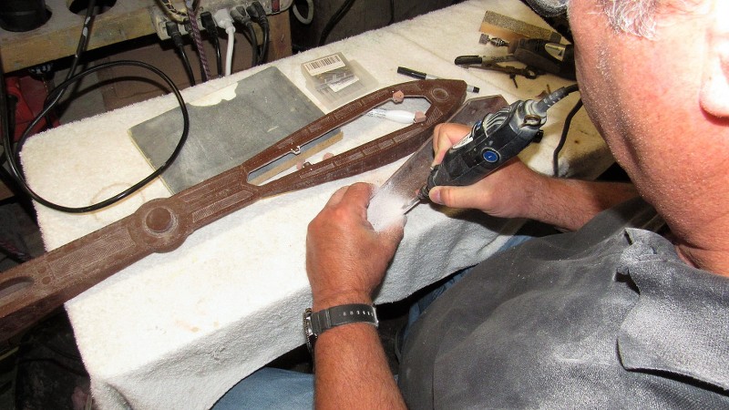
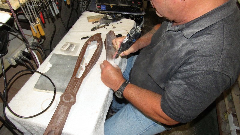
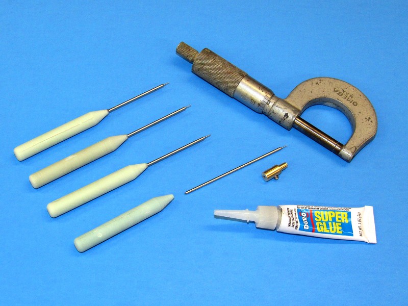
Ellie and I did the Rasher a long time ago. In the years-between my scribing techniques and tools improved. Below I share with you the type of scribing tools I now employ, and how they're made.
The model may be static, but the Craftsman must always be dynamic; on the hunt for better ways to practice his Craft. The true Master is, and always be, the attentive student.
ACID ETCHING
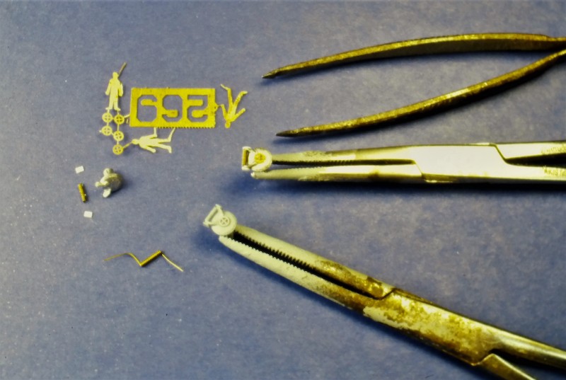
Acid etched brass sheet supplied us with the thin, strong, and highly detailed items needed to outfit the 1/180 RASHER display. Items created using this process included the BPS-2 radar reflector, SJ radar reflector, salvage plates, zincs, hatch hand-wheels, hull name and number and draft marking painting stencils, propeller blades, and human figures. Some of those items, in finished form presented below.
For an in-depth look into the process, go here: Acid-Etching part 1 by David Merriman – CultTVman's Fantastic Modeling
Attaching the small acid-etched hatch hand-wheels.
Acid-etched propeller blades bent, and assembled around a turned brass hub before soldering the entire unit together.
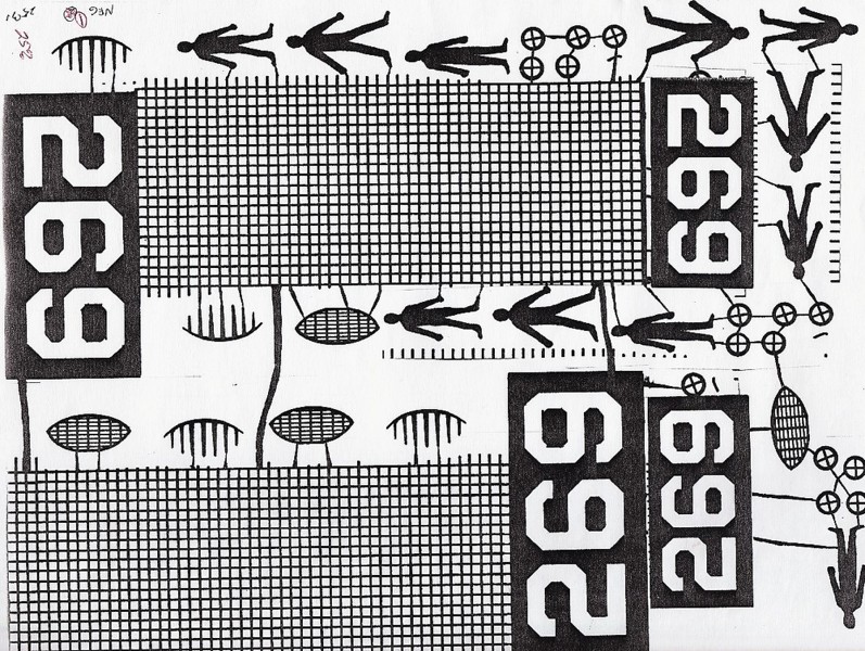
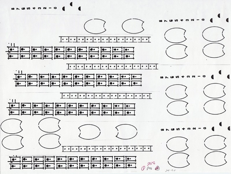
The artwork I prepared for the items I needed for the RASHER job. To achieve a high resolution set of positive films I made the artwork four times the required size, and had the lab guy shoot the film 1/4 the size of the artwork.
Transparencies next to the acid-etched frets of parts.
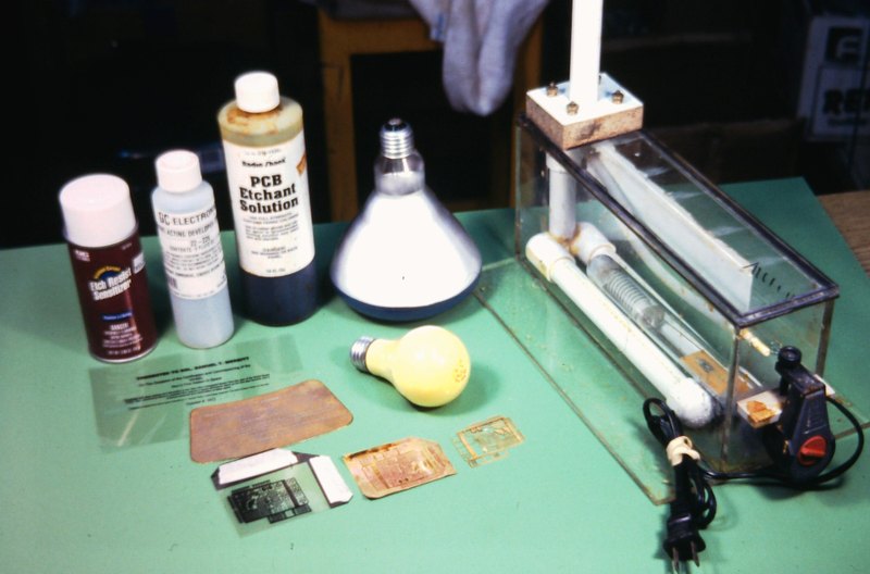
My home-brew acid-etching 'machine'.
Air agitation keeps the hot acid in motion as it cuts away the unprotected portions of brass sheet. A fish-tank heater gets the acid to a working temperature of 120-degrees F.
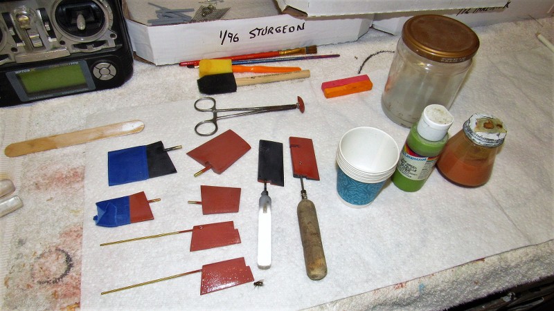
MASKING, PAINTING, AND MARKINGS
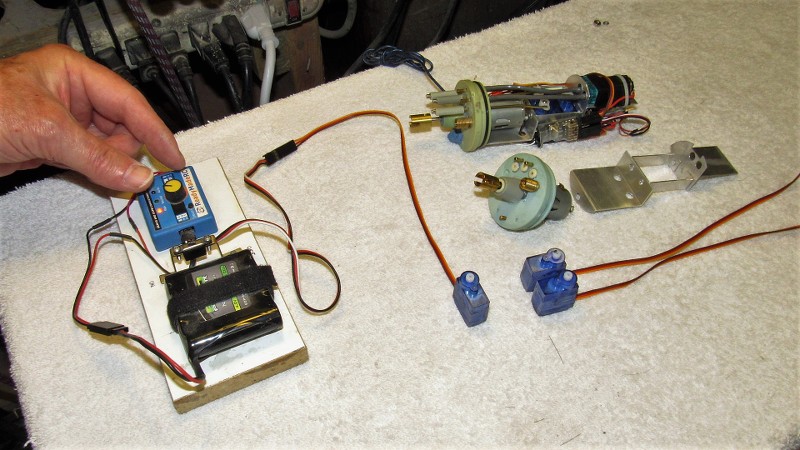
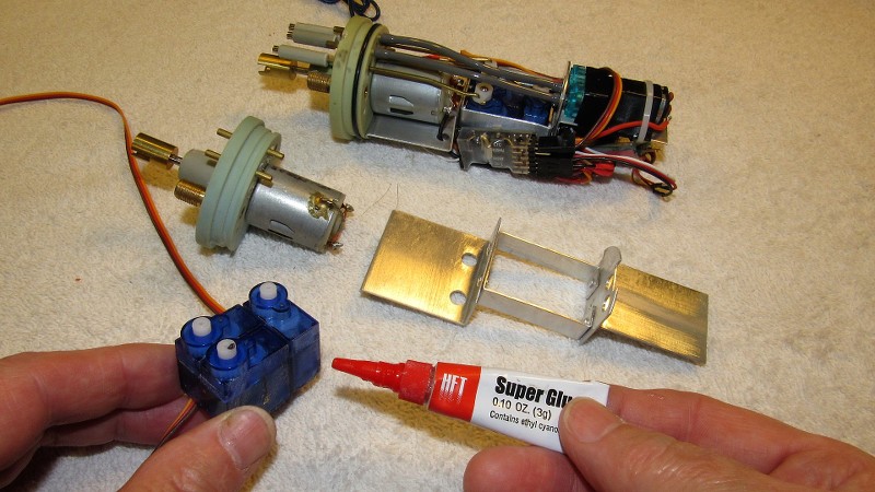
It's my practice to keep as many sub-assembles of a display off the main body and provide each with a keying or fastener arrangement that will insure easy and sure attachment to the display when the time comes to assembly the piece. Such was the case with the control surfaces, big BPS-2 antenna, deck hatches, antenna braces, anchor, cockpit deck, cockpit spray-screen, gyro-compass repeater, sonar windows, propeller shafts and propellers, and hull. Each sub-assemble receiving the same care and attention. All metal items were pickled. Then all sub-asseblies were hit with automotive gray primer, inspected, flaws identified and corrected, sanded, and primed again.
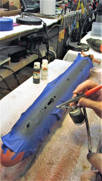
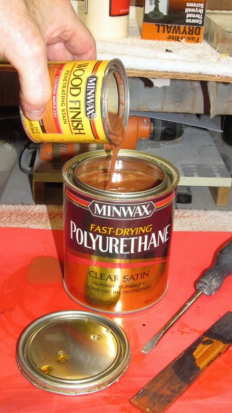
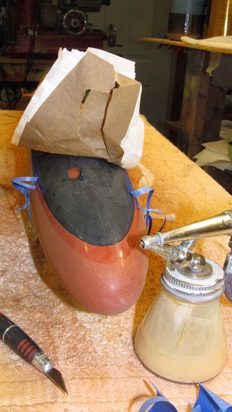
Keeping the sub-assemblies separate like this greatly simplified the painting process. Particularly as the RASHER model was to be painted in the 'Pacific' scheme: gray vertical surfaces, black horizontal surfaces, and an anti-foul red from hull centerline down.
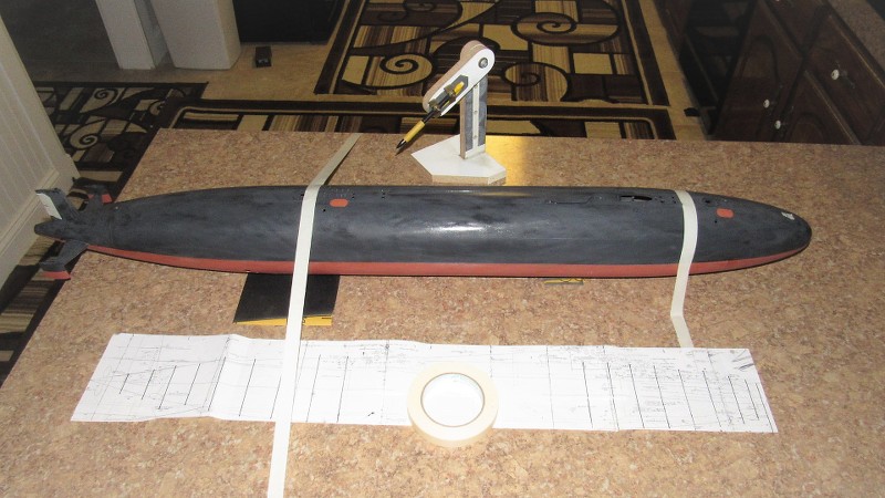
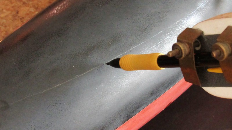
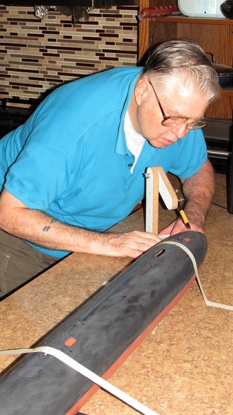
Here I'm showing off the pencil loaded waterline marking tool to pencil the gray-red demarcation lines that run the length of the hull. First, the bottom of the hull was painted anti-foul red, and the demarcation line layed down. The red was masked off and black sprayed on.
URL=https://imageshack.com/i/poCXmSlAj]
[/URL]
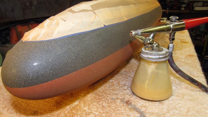
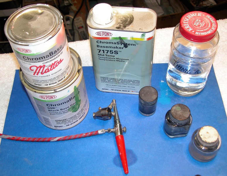
No longer commercially available (thank you, California... you tree-hugging twits!). I was using DuPont ChromaSystem color which are two-part polyurethane paints. Quick drying, tough as nails, and extremely opaque, even when excessively thinned or reduced. Great stuff... now I have to pay a premium for it as this stuff is available today only through back-door outlets like Evil-bay.
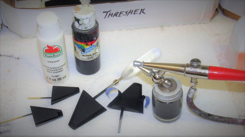
The only air-brush you'll ever need is Paasche's nasty, old, banged up, reliable, ugly, single-action H-model. Period! The only variables with this gun is the size tip you screw into the business end of this thing, adjustment of air pressure (between 5-30PSI), and annular space between tip and needle.
Easy to set up, easy to clean, and won't make you crazy like most double-action guns with all their useless do-dad's.
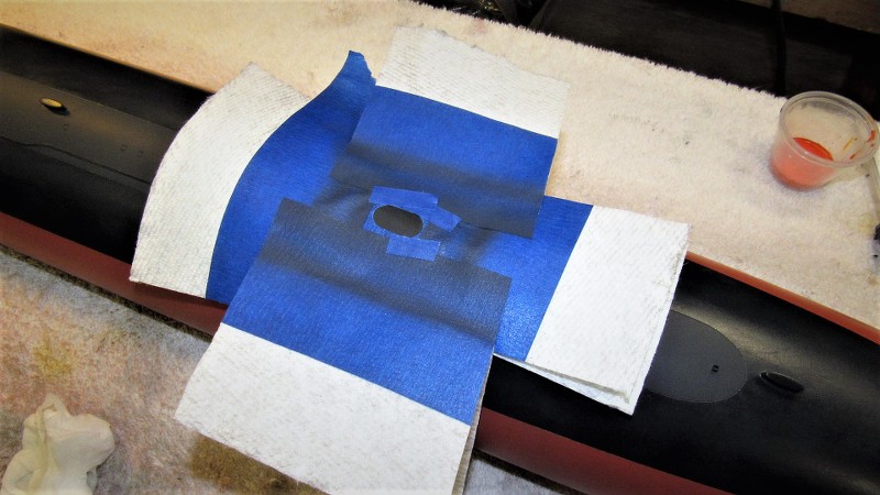
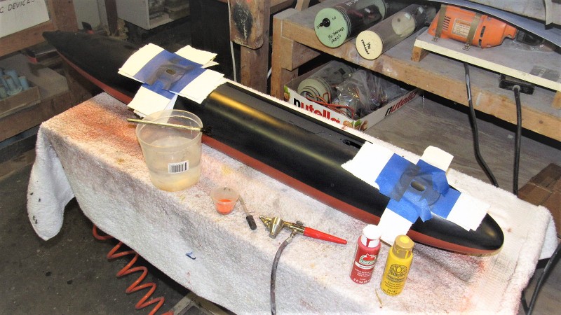
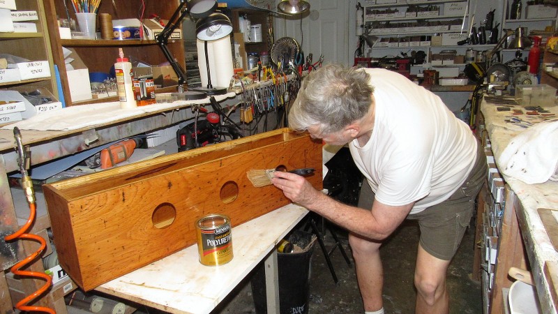
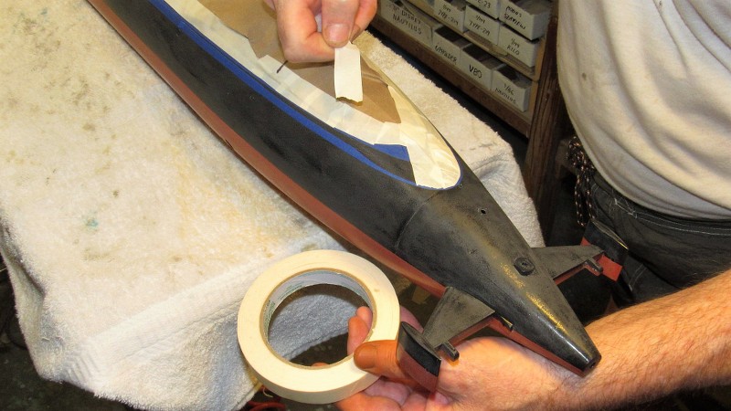
Preparing to paint the sides of the superstructure gray by masking off the black tank-tops. Note all the painted sub-assemblies to the extreme right on this picture. As much painting of parts off-model is done to minimized time consuming masking.
Though the tank-tops and deck were black, the sides of the superstructure were gray almost the entire length of the hull, except at the stern where the gray transitions into the black with a feather-edge. That achieved by placing the 1/4 circle mask a good .25" off the work, backing off the amount of paint shot, and shooting at a high pressure.
Though I had made an acid-etched draft number painting stencil I instead went with some custom made dry transfers -- those 1/180 scale numbers ganged on to a sheet of markings I had made for another job. However, the white hull numbers were shot through acid-etched stencils.
The sail, BPS-2 radar, sonar windows, capstans, antenna posts, and cleats and chocks got the black-gray treatment -- sides gray, tops black. The model was then assembled.
Against my strong suggestion of a very mat clear coat, the client insisted on a semi-gloss finish. So be it. Ugh! The thing wound up looking like a fucking toy!
In this discussion I'm talking about giving permanent shape to heated plastic sheet, forcing it to a specific shape, that shape retained once the plastic cools back to room temperature.
For us, a thermoplastic is that category of plastic that can be heated to a pliable state and then forced, either over a plug/puck/master/pattern/form/whateveryouwanttocallit or into a mold through mechanical or creating a differential pressure between the two faces of the heated plastic sheet.
A very useful technique for the modeler who is looking for a light-weight, thin walled structure that can be rendered in multiples very quickly.
Examine the picture below. The white structure at the bow and the top of the sail are vacuformed items specifically made for this project. Note that the thin walled top-of-sail -- once opening for the retractable masts are punched out -- presents a scale like wall thickness to the edges of those penetrations.
(Many different substrates comprised this model: The polystyrene kit hull; wooden sail, GRP bridge structure at the leading edge of the sail; the huge soldered brass BPS-2 air-search radar; Bondo filled torpedo troughs and hull extension 'knuckle'; and spin-cast white metal detail items.)

The 1/180 scale LIONFISH kits original anchor well was not at all what the RASHER model had, so a vacuformed well was made and grafted into the correct position at the starboard bow. Note the cast white metal anchor just below the anchor well.
Looking at the completed RASHER display one would never know what a Frankenstein Monster this pieced together model was before primer and paint. Seen to good advantage here are the two deck mounted sonar transducer-hydrophone 'windows' -- both of these items were vacuformed from .060" thick white polystyrene sheet.
If you look to the extreme left of this picture you can make out a vacuformed 'dead-light' (optically clear window) that wrapped around the leading edge of the bridge. On the real boat that was a 'safe' place to hide when green-water came crashing down on you in a state-4 following sea! Aft of that atop the open bridge you can see the extendable bridge 'spray-shield'. Another vacuformed item pulled from clear plastic sheet.
Vacuforming over a pattern simply involves placing the pattern over a plenum whose surface is suitably perforated to extract air from between the pattern and heated plastic sheet. A partial vacuum underneath the sheet, with normal pressure above it is the agent of force here; a differential pressure is created between the top of the work and its bottom. As air is extracted from underneath, normal air pressure atop pushes the pliable plastic down to conform to the shape of the master underneath.
On this particular vacuforming job I used a common electric hot-plate to heat the frame supported plastic sheet. From that one sheet I'll get the top of the sail, and the two bow mounted sonar windows.
Alternative heating sources include torches, as seen here; conviction oven; infrared heat-lamp; and hot-air gun. The vacuum source need not be anything more exotic than the household vacuum-cleaner. In these examples I'm using a discarded Barber's clipper-vacuum (On duty nights, off-watch, I could be found examining dumpster contents at the head of each pier... I was a frig'n raccoon!).

It's imperative to secure the plastic sheet in some sort of holding-frame during the heating process, or the sheet will curl up on you. Here are varied examples of frames, patterns, and vacuformed parts.
The problem with forming the plastic sheet over a pattern is the need to account for the thickness of the plastic sheet, otherwise the vacuformed part will be over sized. This requires under-sizing the pattern to account for this. For surfaces parallel to the plane of the frame its a direct correlation, but for those portions with any draft to them, the wall thickness of the vacuformed part will be a bit less than the original thickness of the sheet. This 'drawing out' is a consequence of the draft angle.
A Vacuforming process that renders exacting surface detail and also captures pattern geometry, requires a temperature tolerant tool, within its cavity(s) is pulled the heated plastic sheet.
Here, an IBM display we built which required four well detailed rocket motors, made use of a high-temperature mold into which would be pulled heated .080" thick polystyrene sheet. This type tool -- upper right hand corner -- required the drilling of many small vent channels to pull the air out from between the sheet and the cavities of the tool.
Sometimes it is easier to 'plunge-form' heated plastic like the clear canopy you see here: the pattern is slightly undersized, to account for the wall thickness of the eventual part. After the clear plastic sheet is heated, the pattern is plunged into the sheet. The die, under the sheet, insures a complete wrap-around of the sheet over the pattern. Just another of the many ways one can heat-form a thermoplastic.
Short of some very heroic-expensive-time consuming casting processes, it's all but impossible to render compound curved clear parts like this wrap-around 'green-house' type canopy plunge-formed for this rather large FIREBALL XL-5 model.
SCRIBING
Scribing is the process of cutting channels into the substrate. These channels of a depth, width, and outline so as to suggest hatch covers, access hand-holes, torpedo tube shutter doors, deck planking, and the like.
Scribing is also employed as the first step in punching holes of complicated outline through thin walled structures, such as the retractable mast holes atop the sail, bow-buoyancy flood-drain openings, and superstructure limber holes.
Scribing is a skill learned by practice. One must become proficient at engraving different types of substrates, be it plastic, wood, GRP, Bondo, or even soft metal.
For example, the picture below: The majority of the sail aft of the bridge cockpit is wood, the bridge area is GRP, the top of the sail is vacuformed polystyrene, and the deck is a sheet of polystyrene. Yet all the engraved lines -- no matter the substrate within which they are cut, the engraved lines are of uniform depth and clean of line. If there is any 'art' to model-making, scribing is it!
If a substrate is not receptive to scribing, then you dig out the area to be scribed, back-fill it with Bondo, and scribe that easier to engrave substrate... after putty, sanding, and primer, no one will know the cheat! The hand-holes on the sides of this wooden structure were done this way.
Since we had purchased two of the Revell LIONFISH kits, I took the opportunity to show some before-and-after work. The RASHER hull is above, the raw LIONFISH kit hull is below. Note that the opened up limber holes of the RASHER have a pattern entirely different than the raised limber hole outlines molded onto the sides of the kits superstructure.
Two forms of scribing on display here. The limber holes started out as deeply engraved lines. The shutter doors were engraved after Bondoing and filing flush the shutter door depressions. The RASHER anchor well has yet to be vacuformed and inserted in the correct location just aft of bow-buoyancy.
To insure symmetry and proper spacing of the superstructure limber holes I carefully plotted and cut out a set of holes into a .014" thick piece of brass sheet -- this template used to engrave the limber hole outlines onto the soft polystyrene of the kits superstructure. The engraved outlines guided a #11 X-Acto blade as I carefully opened each hole. The work went surprisingly fast.

To keep this limber hole engraving stencil from sliding over the work I glued a piece of sandpaper to the stencils inboard face. A little index finger pressure and the stencil stayed in place as I engraved a set of limber hole outlines onto the superstructure.
I found that the LIONFISH kits deck in no way represented that of the RASHER. So, I was compelled to produce a scribed deck blank from .040" thick polystyrene sheet.
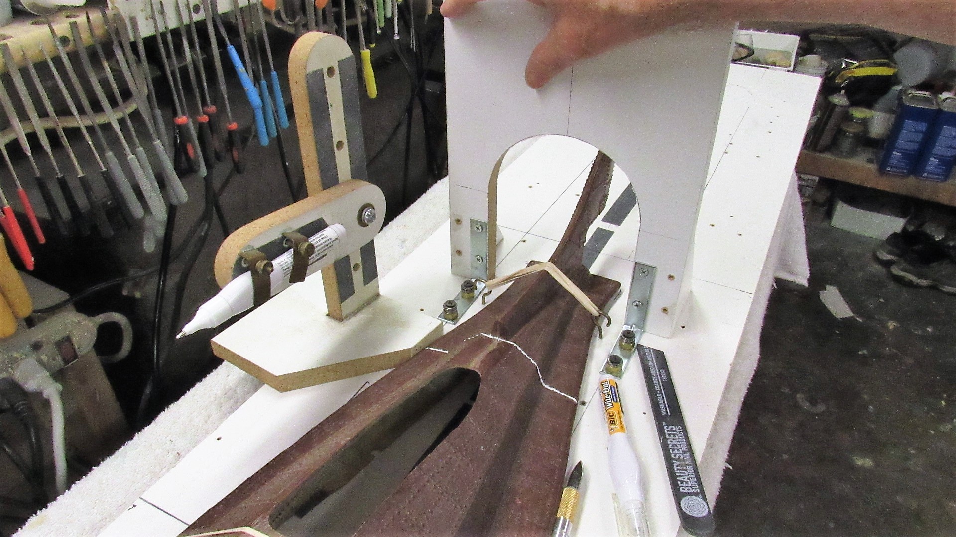
Here I've used a custom made scribing tool to quickly engrave the many parallel lines that give the illusion of well spaced deck planking.
Before gluing the planking down atop the hull I opened up areas that would later receive the two escape trunk escape bell seating surfaces, fixed cleats, muffler access plates, and forward escape trunk side hatch well. After gluing the decking atop the hull it was further scribed to represent the many line and access hatches.
A to-scale shop sketch I developed from my files. Used to guide me during the deck, superstructure, hull, and sail scribing.
Holy shit!!!!... is that 35 year old blood?
Ellie and I did the Rasher a long time ago. In the years-between my scribing techniques and tools improved. Below I share with you the type of scribing tools I now employ, and how they're made.
The model may be static, but the Craftsman must always be dynamic; on the hunt for better ways to practice his Craft. The true Master is, and always be, the attentive student.

ACID ETCHING
Acid etched brass sheet supplied us with the thin, strong, and highly detailed items needed to outfit the 1/180 RASHER display. Items created using this process included the BPS-2 radar reflector, SJ radar reflector, salvage plates, zincs, hatch hand-wheels, hull name and number and draft marking painting stencils, propeller blades, and human figures. Some of those items, in finished form presented below.
For an in-depth look into the process, go here: Acid-Etching part 1 by David Merriman – CultTVman's Fantastic Modeling
Attaching the small acid-etched hatch hand-wheels.
Acid-etched propeller blades bent, and assembled around a turned brass hub before soldering the entire unit together.

The artwork I prepared for the items I needed for the RASHER job. To achieve a high resolution set of positive films I made the artwork four times the required size, and had the lab guy shoot the film 1/4 the size of the artwork.
Transparencies next to the acid-etched frets of parts.

My home-brew acid-etching 'machine'.
Air agitation keeps the hot acid in motion as it cuts away the unprotected portions of brass sheet. A fish-tank heater gets the acid to a working temperature of 120-degrees F.
MASKING, PAINTING, AND MARKINGS
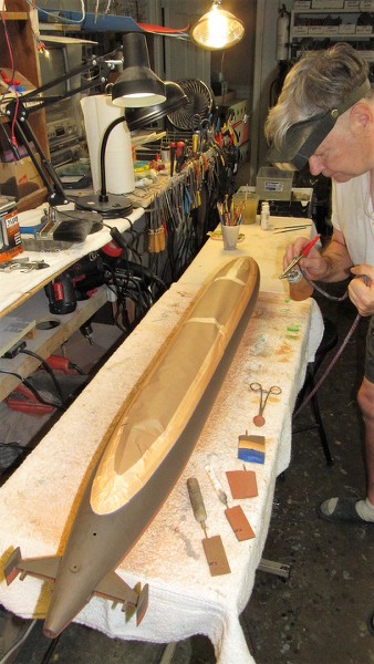
It's my practice to keep as many sub-assembles of a display off the main body and provide each with a keying or fastener arrangement that will insure easy and sure attachment to the display when the time comes to assembly the piece. Such was the case with the control surfaces, big BPS-2 antenna, deck hatches, antenna braces, anchor, cockpit deck, cockpit spray-screen, gyro-compass repeater, sonar windows, propeller shafts and propellers, and hull. Each sub-assemble receiving the same care and attention. All metal items were pickled. Then all sub-asseblies were hit with automotive gray primer, inspected, flaws identified and corrected, sanded, and primed again.
Keeping the sub-assemblies separate like this greatly simplified the painting process. Particularly as the RASHER model was to be painted in the 'Pacific' scheme: gray vertical surfaces, black horizontal surfaces, and an anti-foul red from hull centerline down.
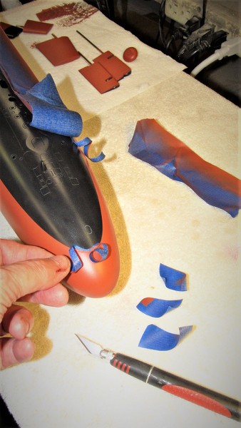
Here I'm showing off the pencil loaded waterline marking tool to pencil the gray-red demarcation lines that run the length of the hull. First, the bottom of the hull was painted anti-foul red, and the demarcation line layed down. The red was masked off and black sprayed on.
URL=https://imageshack.com/i/poCXmSlAj]
No longer commercially available (thank you, California... you tree-hugging twits!). I was using DuPont ChromaSystem color which are two-part polyurethane paints. Quick drying, tough as nails, and extremely opaque, even when excessively thinned or reduced. Great stuff... now I have to pay a premium for it as this stuff is available today only through back-door outlets like Evil-bay.
The only air-brush you'll ever need is Paasche's nasty, old, banged up, reliable, ugly, single-action H-model. Period! The only variables with this gun is the size tip you screw into the business end of this thing, adjustment of air pressure (between 5-30PSI), and annular space between tip and needle.
Easy to set up, easy to clean, and won't make you crazy like most double-action guns with all their useless do-dad's.
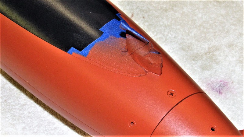
Preparing to paint the sides of the superstructure gray by masking off the black tank-tops. Note all the painted sub-assemblies to the extreme right on this picture. As much painting of parts off-model is done to minimized time consuming masking.

Though the tank-tops and deck were black, the sides of the superstructure were gray almost the entire length of the hull, except at the stern where the gray transitions into the black with a feather-edge. That achieved by placing the 1/4 circle mask a good .25" off the work, backing off the amount of paint shot, and shooting at a high pressure.

Though I had made an acid-etched draft number painting stencil I instead went with some custom made dry transfers -- those 1/180 scale numbers ganged on to a sheet of markings I had made for another job. However, the white hull numbers were shot through acid-etched stencils.

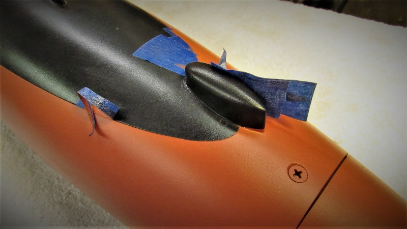
The sail, BPS-2 radar, sonar windows, capstans, antenna posts, and cleats and chocks got the black-gray treatment -- sides gray, tops black. The model was then assembled.
Against my strong suggestion of a very mat clear coat, the client insisted on a semi-gloss finish. So be it. Ugh! The thing wound up looking like a fucking toy!
- Joined
- 18 March 2013
- Messages
- 978
- Reaction score
- 2,851
DEADLIGHTS
part-1
part-1
In navy parlance a 'deadlight' is any transparent material that permits sunlight into an otherwise dark interior. If the transparent lens of the deadlight passes enough light without significant distortion then that deadlight also serves as a window to the world outside the hull: port-hole; wind-screen, canopy; Navigator's sextant dome; running light lens; search-light lens; observers blister, etc.
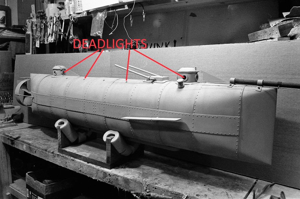
The term deadlight as applied to modern combat submarines describes the transparent windows set into the leading edge of the sail, near the bridge station, used by watch-standers to give them a view forward when on the surface in rough weather. The structure behind the deadlights, like the rest of the sail, is free flooding therefore the deadlights never see a differential pressure greater than wind-blown waves.
As this discussion is on the practical problems of forming and installing such transparencies, I've pulled up examples of these transparencies (or painted representation of transparencies) from both submarine model work as well as aerospace displays we've been involved with over the decades. Regardless of subject, the methods of fabrication, installation, fairing in, polishing, masking, and painting remain the same; and the examples presented here, regardless of subject, serve to instruct.
Ellie and I gained a foot-hold in the display building profession by offering our clients above average detailing. That means knowing where the viewers – our audience -- would concentrate their attention. With an aircraft display the viewer always looks into the transparency enclosed 'office'. The cockpit. That's where all the fun stuff is housed.
Where competitors would offer a solid cockpit canopy with a painted on simulation of a transparency, we would model the cockpit and enclose it in a suitable transparent cockpit enclosure; that enclosure so expertly integrated with the surrounding opaque structure upon which it sat as to look 'real'.
That attention of detail -- and joy of representing an interior within the display – carried on when our client base transitioned from defense contractors and private commissions to the needs of the r/c and static submarine model trade.
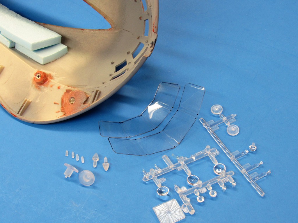
A good example of a model submarine making use of transparencies is that of this enhanced SEAVIEW model kit, with its big 'windows' at the bow through which the crafts 'observation compartment' can be viewed; to the sail and stern navigation lights; to the big bow mounted search light; and the downward pointing lamps near the tips of the manta-shaped bow.
The just machined acrylic parts to the extreme left were lathe turned from round stock. The parts and trees are clear items of the Moebius Models SEAVIEW kit. And the two large, creased window section above are cut and bent to shape from .040” CAB, these to replace the kit provided window parts with their distorted optics.
There are all sorts of rigid transparent plastic sheet and shapes commercially available: Acrylic (Plexiglas is one common trade name), polyethylene, polyvinyl chloride (PVC), polystyrene, and cellulose acetate butyrate (CAB), to name but a few.
We long ago settled on three transparent, thermoplastic types suitable for model work: Acrylic (Plexiglas is a common trade name) because of its hardness and wide selection of sheet thickness and extruded shapes such as round, square, tube, 'L' and 'H'; clear polystyrene sheet and kit 'trees'; and clear sheet CAB.
We favor CAB clear plastic sheet because of it's ability to be heat-formed without incident, takes a crease without cracking or parting, and its low abrasion resistance, which makes polishing out scratches and paint over-spray a quick and easy operation.
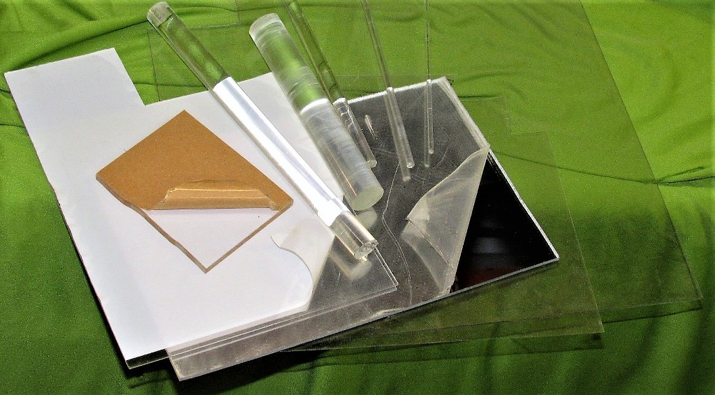
Here are arrayed acrylic round stock of varied diameter as well as a small hunk of rather thick acrylic sheet; some CAB sheet on the bottom, and a big piece of 'mirror' acrylic sheet, such as used to fake a transparency when there is no room within the models structure for interior details – a reasonable cheat in such circumstances.
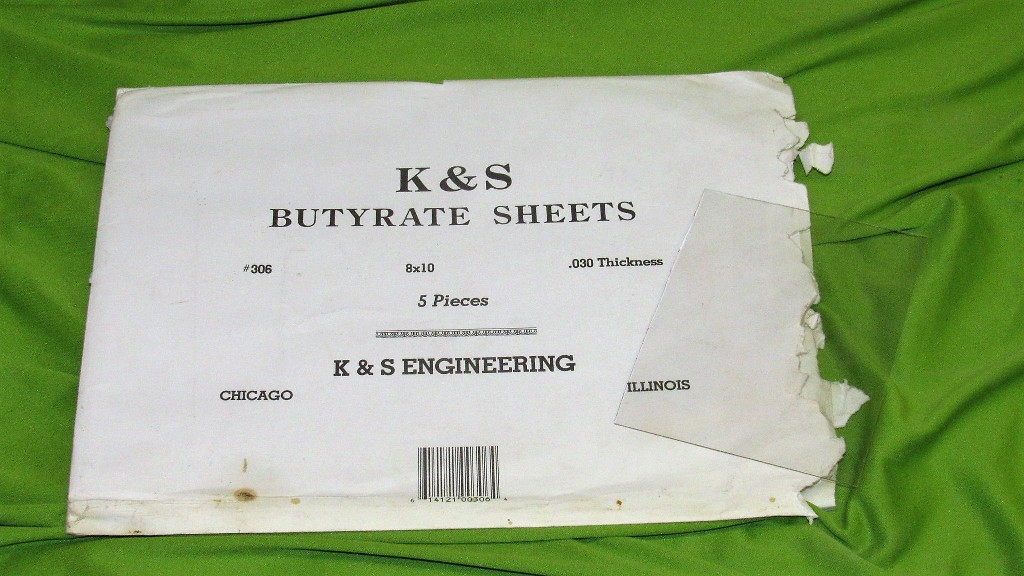
CAB is my go-to type of transparent plastic sheet. I bought packages of varying thicknesses nearly a half-century ago, and the stuff is as clear and work-friendly as the day I purchased it.
OK. Now. The nitty-gritty of how to represent transparent structures on the model, and do it in a way that adds to the quality of the display, not distract from it.
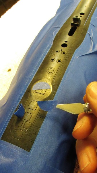
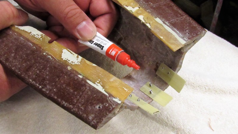
Transparencies Derived From A Liquid A departure from the use of solid machined or sheet clear plastic is the use of a clear liquid resin to form-in-place windows in per-existing window frames, such as these inserts with open window frames inlaid flush with the surface of this effects miniatures fuselage.
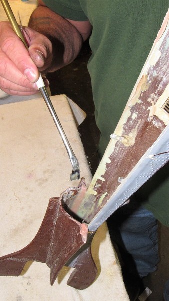
A backing mask within the fuselage was affixed behind the open window frames, then catalyzed clear epoxy laminating resin was applied with an eye-dropper within each open window frame and left to cure hard. Excess hardened epoxy was filed, sanded, and polished to follow the contour of the fuselage. The inside masking was removed to reveal credible looking transparent passenger windows. Back-lighting the windows would later render that 'lived in' look to the miniature.
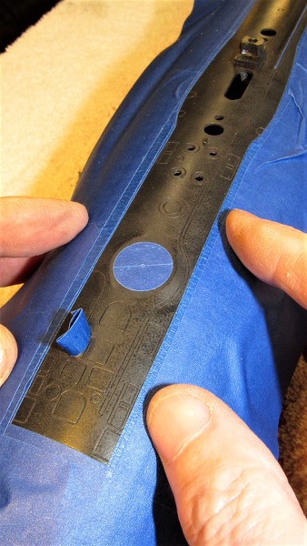
Or, reversing the process from the airplane example:
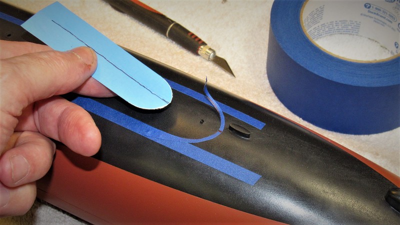
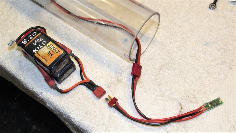
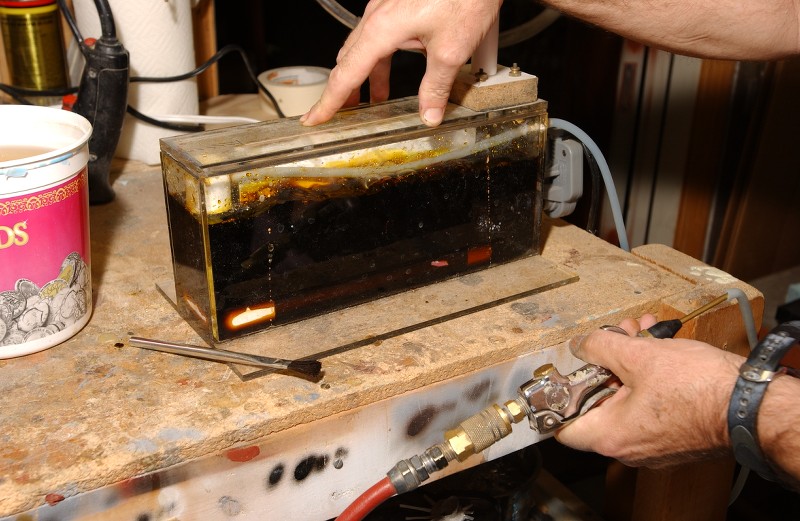
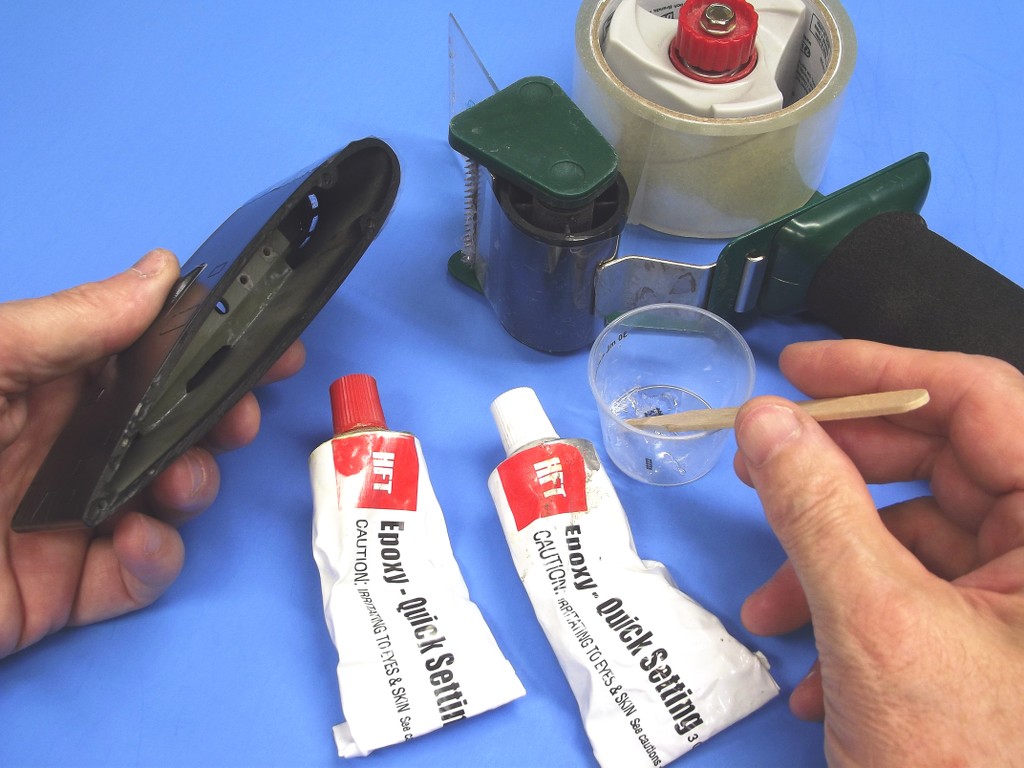
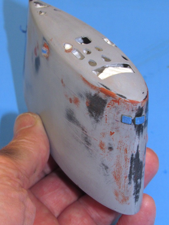
This 1/96 KILO model had its deadlight openings masked off, using packaging tape, from the outside. The catalyzed epoxy built up and applied to the inside of the sail. Application of the clear epoxy made easier by thinning the catalyzed adhesive with a bit of MEK or lacquer thinner.
It usually takes about three layers of epoxy to achieve a transparency approximating the wall thickness of the surrounding structure. You have to moderate how much wet epoxy is laid in – too much and it will run. Hence the need for multiple layers of epoxy, not just one massive glob of goo.
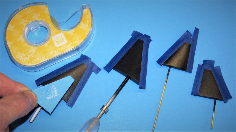
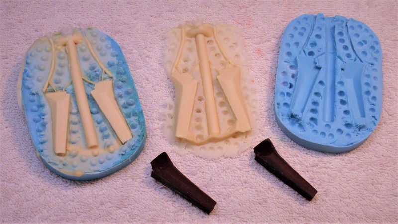
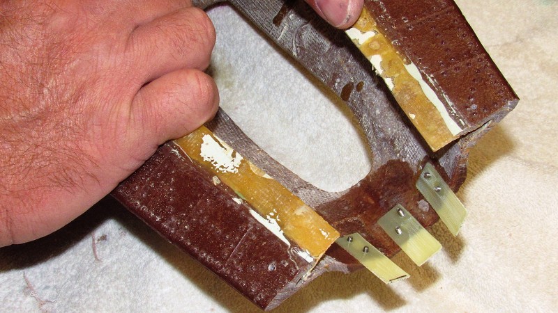
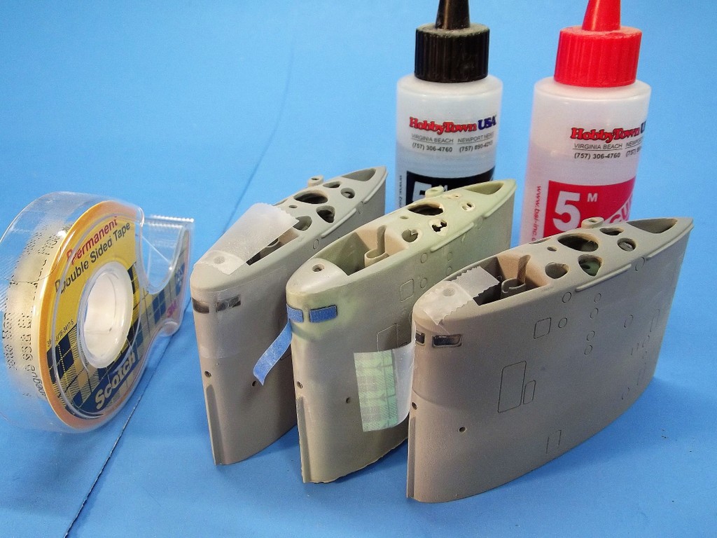
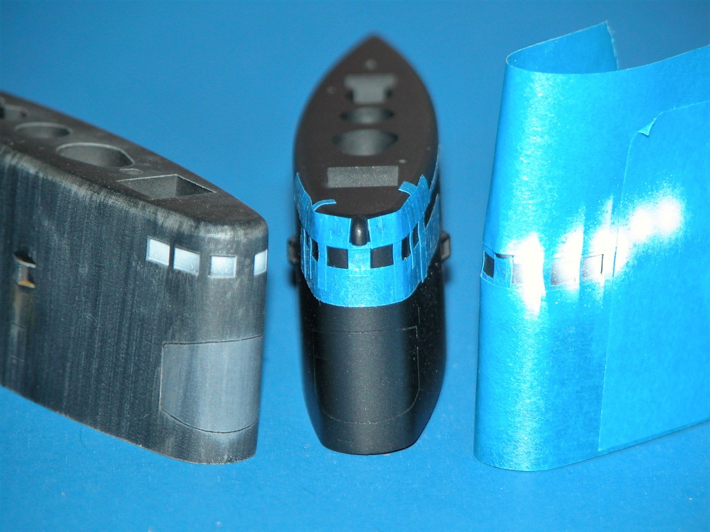
These three sails of 1/96 BLUEBACK kits demonstrate the three major steps in the liquid deadlight process: To the left, the outside of the deadlights are masked (it does not matter if the mask is clear or opaque), and the epoxy is applied from within the sail.
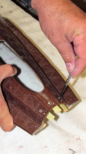
The sail on the right, with the epoxy deadlights cured hard, has had its external mask slightly pulled away to reveal the raw epoxy deadlights. From this point the epoxy deadlights are sanded and polished flush to the contour of the sails leading edge.
The center sail, it's deadlights polished to optical clarity, now receives individual masks in preparation for spot priming and paint.
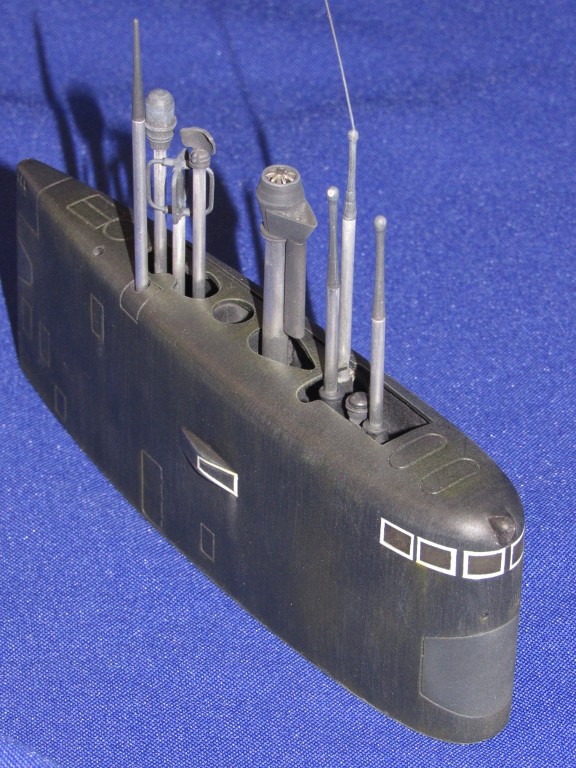
And the completed 1/96 KILO and BLUEBACK sails. Both outfitted with deadlights employing the transparencies-derived-from-a-liquid method.
Credit to Dave Manley who originated these fine r/c model submarine kits and who refined and popularized this method of deadlight representation.
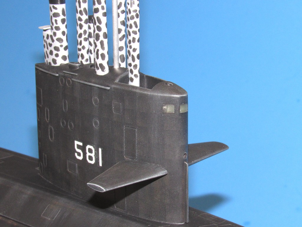
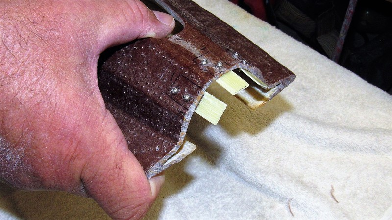
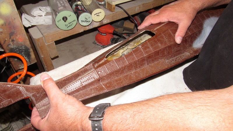
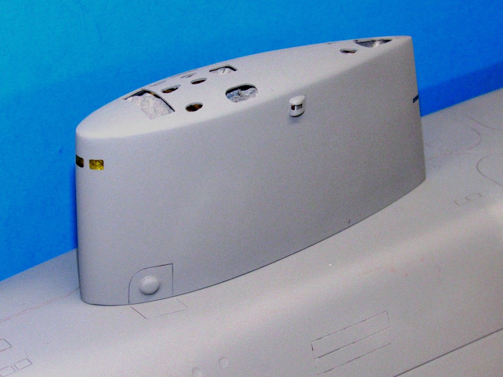
One more example of a model submarine sail outfitted with leading edge deadlights made this way, is this 1/96 WEBSTER sail.
Note that the interior of this ready for primer structure has been stuffed with paper towel shreds. This type masking to prevent primer (and later paint) from getting into the sail and spoiling the optical qualities of the deadlight transparencies. I also draw your attention to the blue masking over the clear lens of the starboard running light, and at the trailing edge a mask covering the clear plastic lens of the emergency stern light.
Applying the first layer of primer. The masks, inside and outside the sail structure, preserve the transparency of the deadlights and running light lenses.
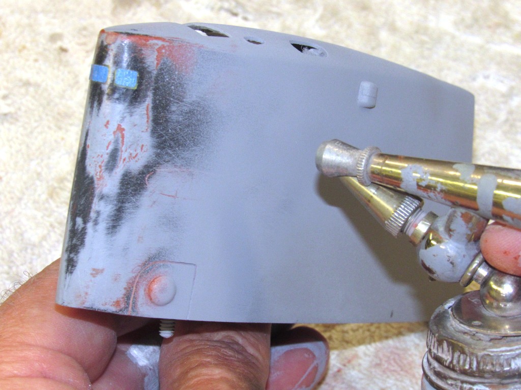
External masking temporarily removed to check the work.
Paint Simulated Transparencies Sometimes the modeler is just as well served by simply simulating a transparent deadlight, window, astrodome, or other such structure with an off-shade paint followed by a gloss clear coat. Often this cheat is employed owing to the subjects small size where practical transparencies would be a waste of time. Or, a situation where a practical deadlight transparency would be subject to damage from collision or rough handling while in or near the water.
These little 1/144 scale KILO model sails had their bridge deadlights represented with an off-white. Note that the off-white is sprayed carefully to leave just a hint of dark-gray in the lower edges of each deadlight frame. This give an illusion of 'depth' to each simulated deadlight.
Paint simulation is an acceptable cheat for small models representing transparencies that do not require back-lighting.

Though this large 1/60 scale ALBACORE model would have looked a lot better with a proper heat-formed, compound curved bridge deadlight/spray-shield transparency, I elected to retain the much stronger cast resin area – ever fearful of collision damage with surface traffic as I race my toy submarine beneath the surface. This move compelled me to simulate the deadlight with paint. A darkened silver. I went with the silver over an off-white as the location, up high would catch more sun, and that would read better to the observer as a transparency.

Only the forward portion of the deadlights received an heavy opaque coating of silver paint; I left just enough black at the after end of the deadlights to suggest 'depth'. What made this simulated transparency pop was the gloss over-coat, which produces the reflectivity of a transparency possessing compound curves. Almost like the real thing!
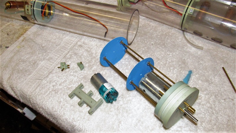
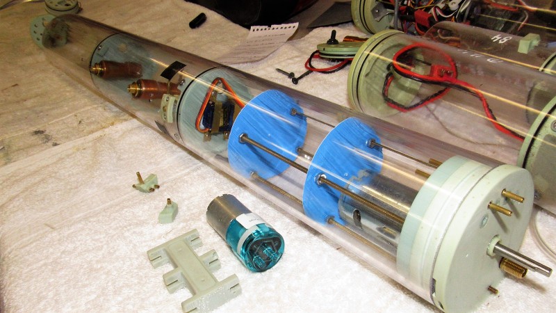
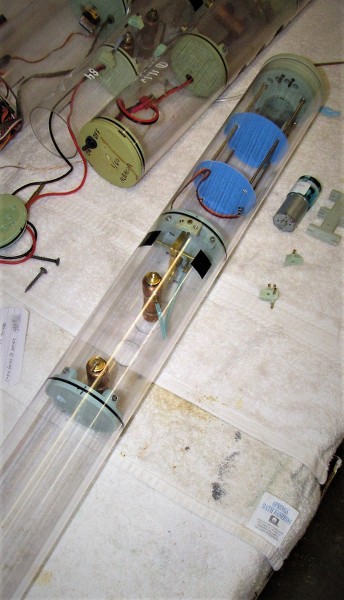
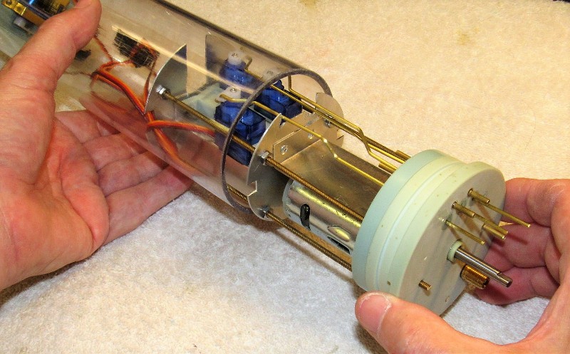
Mirrored Acrylic Sheet In those situations where the transparency is so large that it can't be effectively represented through a paint simulation, and there is not enough real-estate within the model for a proper interior, then a good effect of transparency can be achieved by using a mirror coated plastic sheet. Such is the case with this big model of the FS-1 (the SEAVIEW's Flying-Submarine).

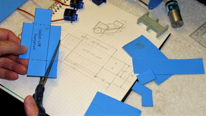
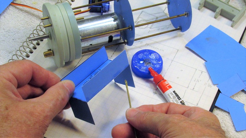
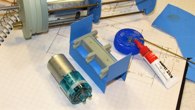
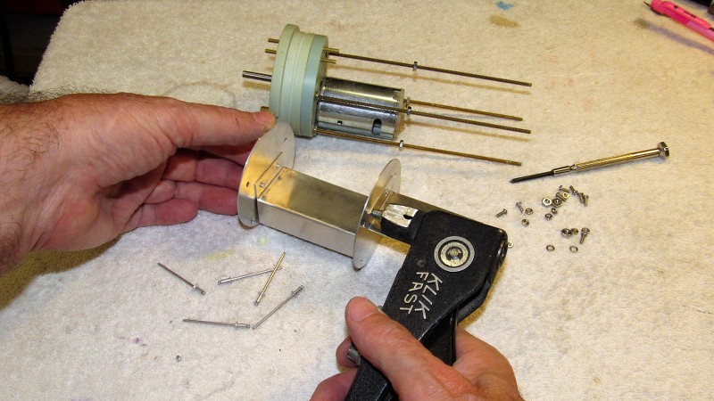
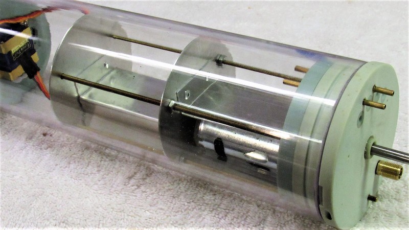
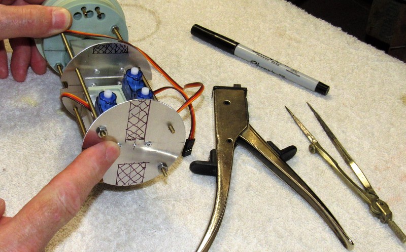
I would have loved to have had the internal space to gin up a proper interior – which would have looked great through a proper set of transparent deadlights. But, as you can see, every square-inch of internal space was taken up by the water tight cylinder, propulsion units, battery, and flotation foam. The mirrored plastic sheet was my only viable alternative to transparencies. Nuts!
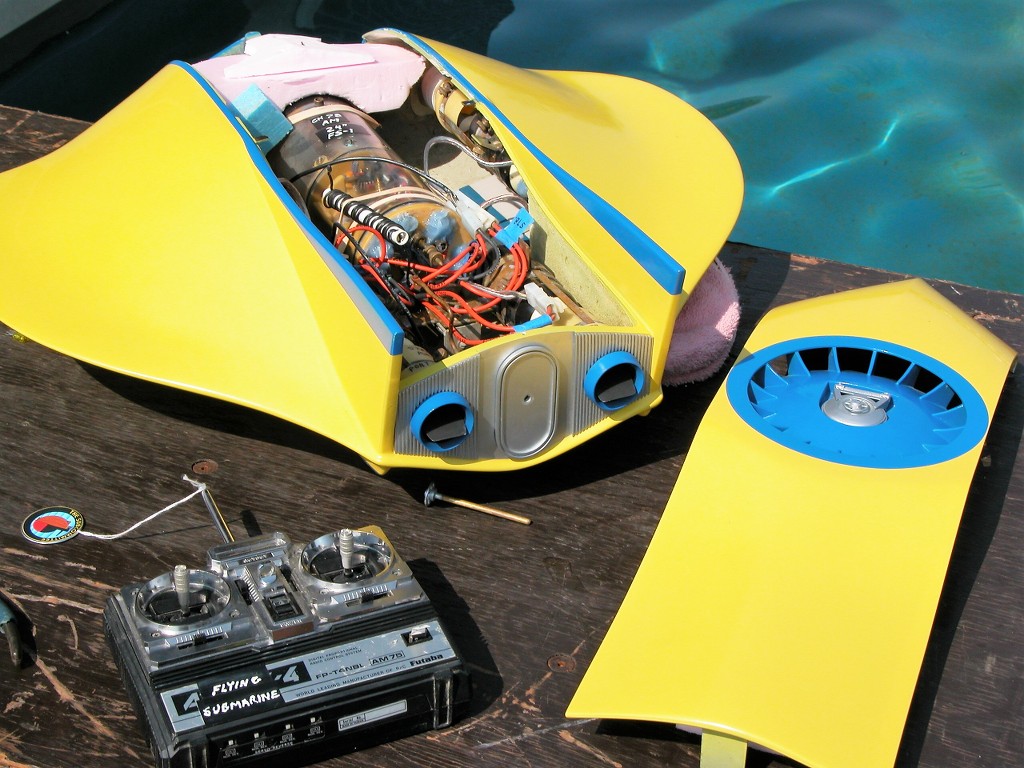
Mirrors. A viable cheat for actual transparencies.

Last edited:
- Joined
- 18 March 2013
- Messages
- 978
- Reaction score
- 2,851
DEADLIGHT
part-2
part-2
Heat Forming Transparencies
Those situations where an actual transparency of compound-curve is needed (an airplane canopy, a spaceships astrodome, a submarines 'greenhouse' for example), one is best served to take advantage of the thermoplastic property of CAB. Vacuforming is one form of the process: heating sheet plastic to a state of softness and then forcing the sheet over or into a form to give it the desired shape. Once cooled to room temperature the sheet plastic is once again hard and will retain the new shape unless heated again. Heat forming is the technique of choice for production of clear parts of extreme curvature.
An example of a heat-formed transparency of compound curves is this well glazed cockpit at the front end of this effects miniature:
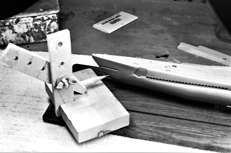
A wooden pattern of the cockpit area was turned and split longitudinally into halves. The cockpit patterns placed on a plenum – essentially a box whose top is perforated. On one side of the plenum box a suction hose leading to the vacuum pump is attached.
Secured within a two-piece wooden frame a sheet of CAB is heated and quickly placed over the patterns. The bottom of the frame makes a seal between the bottom of the sheet and the top of the plenum. Air is extracted from the pattern side of the sheet. Immediately the differential air pressure between top and bottom of the sheet pushes it down, tightly wrapping the soft sheet over the two patterns. When the sheet cools it hardens, the vacuum is broken, the frame patterns pulled away, the sheet is removed from the frame, the two ogive halves cut out, trimmed, and assembled into a clear nose section ready to be joined to the rest of the model.
The completed clear nose section is glued to the rest of the model. The union between them filled, filed, sanded, primed, and inspected – those steps repeated til a seamless integration between the transparent and opaque portions of the model was achieved.
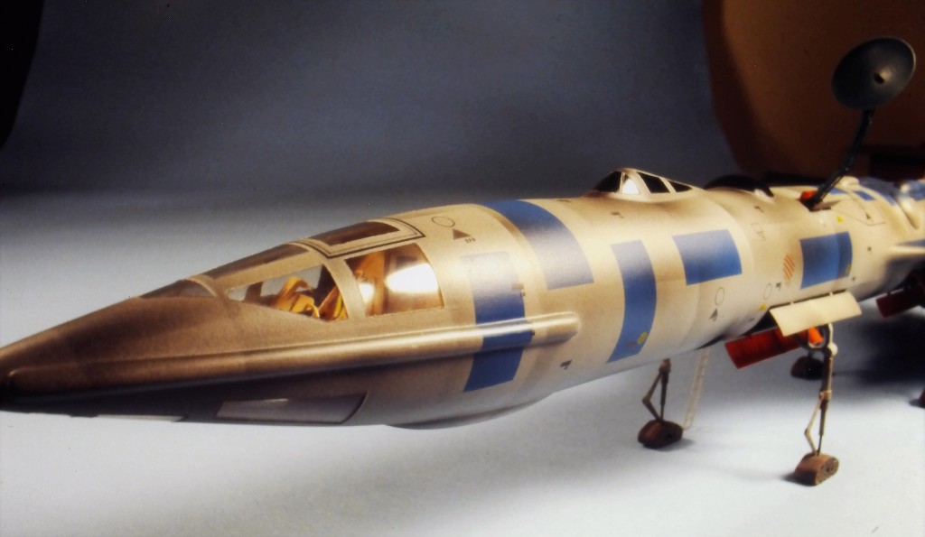
Though this example of vacuforming is being performed on opaque, white, polystyrene plastic sheet, the same process applies to CAB clear plastic sheet.
Note the use of a wood frame to hold the outer boarders of the plastic sheet as the plastic within the frame is heated. Note also the deep draft of these well pieces; those vacuformed parts eventually inserted within the top of a SEAVIEW sail master later used to make a rubber tool.
To better illustrate, I've laid prepared vacuformed inserts next to the wood patterns that gave them shape – one representing the well of the open bridge. The other a well to accommodate the retracted radar antenna.

The vacuum source can me nothing more overwhelming than the household vacuum-cleaner. The differential pressure between top and bottom of the heated plastic does not have to be extreme.
Here you see the vacuum plenum; the holding frame; and a just pulled upper half of a saucer shaped hull – part of a commissioned 29” long model of Star Trek's ENTERPRISE.

No better example of a display employing practical transparencies to show off a vehicles interior furnishings and do-dads than this rather large model of the FIREBALL XL-5 – an early commissioned work for one of the Editor's of Starlog Magazine.
Both the FIREBALL Jr. and main body had their own cockpit transparencies. One in the shape of a half-ogive canopy, the other a rather bulbous tear-drop shaped canopy. Both of these transparencies possessed extreme compound curves, making heat-forming the only viable fabrication means of producing transparent canopies from scratch.
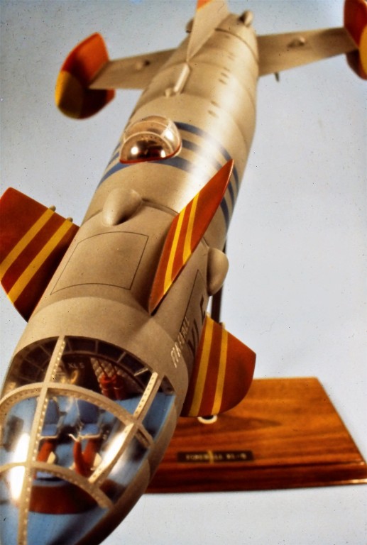
The formed half-ogive and bubble canopies in process of being polished to optical clarity before being assembled to their respective hull structures. The patterns that imparted shape to the canopies during the heat forming process are in foreground.

This is what the FIREBALL XL-5 transparent canopies looked like right after being formed over their respective patterns. Note the use of two-piece, hinged wooden frames to hold the plastic sheet during the heating and forming phases of manufacture.

When done right the union between clear and opaque portions of the display should be undetectable.

Working as a third-party contractor we got the job of building two von Braun designed spacecraft models for IBM.
Those vehicle concepts (interpreted by illustrators Bonestell, Klep, and Freeman) came to the public's eye in the early 50's through articles that were published in Collier's magazine and later appeared in several Viking Press books dealing with the subject of space-flight.
This model of the Moon Reconnaissance Ship featured a wide clear, truncated, hemispherical Command Station canopy atop the Personnel Sphere, and a much smaller hemispherical sextant equipped star-sighting astrodome to the side of the Personnel Sphere. Both of these transparent items were heat formed from CAB plastic sheet.
(That work eventually displayed during a one year residency on the second-floor of the National Air & Space Museum in Washington D.C. A thrilling surprise for Ellie and me).
A well built model aircraft will draw the observer's eyes to the cockpit interior, so it is with spacecraft...
… What's behind that clear canopy? What wonders of model-building will be found in the dark interior of that model?
I try not to disappoint.

Under that big transparency is a fair representation of the illustrated 'command-chair' and attached optical instruments which were visualized in the magazine and books mentioned previously.
Incidentally, I bet Mr. Freeman (a master of detailed cut-away illustration) was influenced by his study of the powered gun-turret style White-Sands and Canaveral rocket tracking cameras developed at the dawn of the space-age.
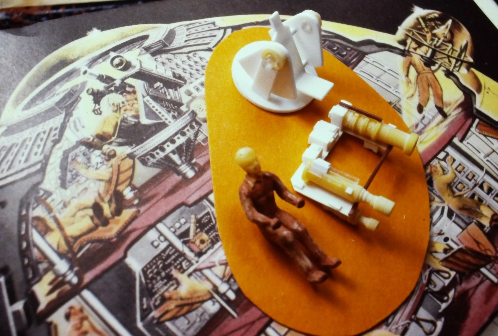
You can just make out the two semi-spherical vacuformed transparencies below in this rogues-gallery shot of parts fabricated for the Moon Reconnaissance Ship display.

Ironically, about the time of our IBM work, Bob Burns, out in California, who was very much plugged in with the effects houses and talent that serviced the film industry there approached me to consider joining a team of other professional model-builders engaged in the restoration of the much abused big 'hero' miniature of the Spaceship-One from the George Pal movie, The Conquest Of Space.
At the time I was serving on a destroyer tender, which, for embarked Diver's amounted to shore-duty, meaning I could squeeze in enough free-time to take on the job. The stars were in proper alignment.
Spaceship-One was made up of three separable units: The big wing which would glide itself, with the return-to-earth ship mounted on its back, to a landing on Mars. A booster that would provide the Delta-V to get the craft from Earth orbit to Mars, and also provide the breaking required to get the rest of the ship into the Martian atmosphere. And the return-to-earth ship.
The design of the entire Spaceship-One effects miniature was loosely based on the ship proposed in the book, The Mars Project, authored by Dr. Wernher von Braun in the late 40's (which, incidentally was the source material for the above mentioned magazine articles and Viking Press books).
This photo, a frame enlargement from a copy of the movie, shows the dramatic lift-off of the return-to-earth ship from the discarded wing section.
It was agreed I would restore the return-to-earth ship on the east coast (I was stationed in Florida at the time), while the booster and wing element would be handled by the Burbank guys on the other side of the country. Luminaries of the special effects industry they were. Bob and Dennis Skotak, Bob Burns, Mike Minor, and a few guys from the ILM crew.
Wow!
They shipped the return-to-earth miniature – what was left of it – to me. This was our introduction to the big time of effects model building.

The movies return-to-earth ship miniature was practical in that it contained custom made solid rocket motors who's grain was formulated and cast to throw plenty of smoke and fire, but develop little thrust, as the movies take-off scene employed wire-work to actually lift the miniature up and away from the miniature set depicting the Martian surface. The smoke and fire produced by the miniatures 'engines' was for effect, not propulsion – they didn't want this thing to punch a hole through the studio roof!
I assume that multiple takes of that take-off scene were required because, as I dug into the return ship miniature, I found plenty of char within the GRP hull, and the two transparencies (off model when I got it), though well distanced from the nozzles, had yellowed with age and also evidenced distortion from heat.
And the three stabilizing fins were missing – one of the California guys informed me that they were broken off previously by a Jerry Lewis production crew as they rigged the miniature for a first-unit gag shot. All for not: that footage wound up on the cutting-room floor.
(Most post-production effects miniatures don't fade away, they are first tortured to death then unceremoniously tossed into a dumpster!)
In foreground, left-to-right, is the cockpit hemisphere; astrodome; two smelly, terribly decomposing latex space suited figures; the pipe-stand hard-point that held the miniature during some of the in-flight shots; and a fin pattern used to make a tool from which I cast glass reinforced resin replacements.
Previous to this shot I had radially split the body of the ship to get at the pipe-stand support and powder-rocket support structure. The miniature was then put back together. The after portion has already been cleaned up and a check coating of primer laid down.
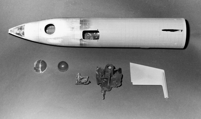
Part of the work required to put this little piece of film history right was to lathe turn patterns of the forward cockpit canopy (the original, for some reason, was a full hemisphere) and side mounted hemispherical astrodome. Over those patterns I vacuformed new, optically clear replacement transparencies from CAB.
Below is a shot of the completed Spaceship-One hero miniature, restored and ready for display at the Bob Burns Museum.
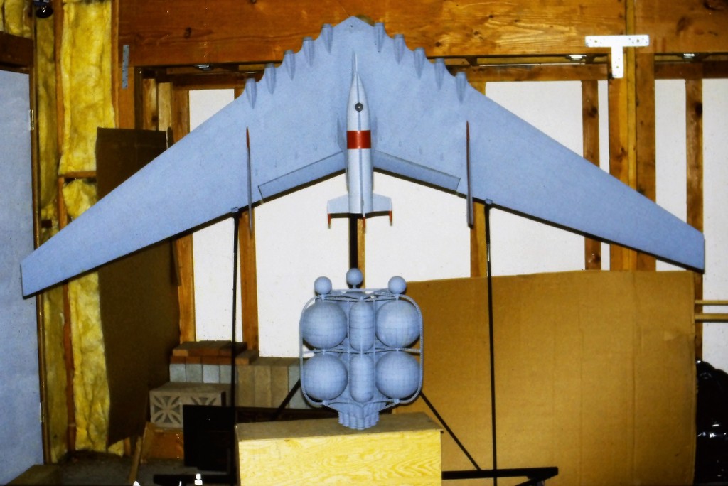
This scene is a live set, representing a POV from outside the ship, looking through the astrodome at members of the Mars expedition.
As I endeavored to capture and model as many elements of the ships interior that could be seen through the transparencies, I studied still shots like this and constantly reviewed a VHS copy of the movie.

A gimbaled astrogator's couch and attached optical equipment was modeled to scale with the miniature and fit to the inside of the vacuformed astrodome.

Though not practical on the miniature, the full sized set featured a sliding two-piece section of streamlined hull just ahead of the cockpit transparency that was lowered into the hull to afford a view for the pilots as they lined up for the landing on Mars.
The miniature obviously had a plug-in section that has been long lost, so I made a new one that could be plugged in or removed depending on the demands of the display.
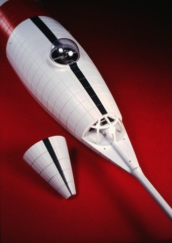
The replacement cockpit transparency mounted at the front of the return ship. Within you can make out the crew ladder. (sick puppy that I am I even proved an out-of-sight 'space-speed-indicator' further down the ladder). Though no evidence of the brace-work under the canopy existed on the return ship miniature, it was most evident on the live set, so I modeled those elements as well.
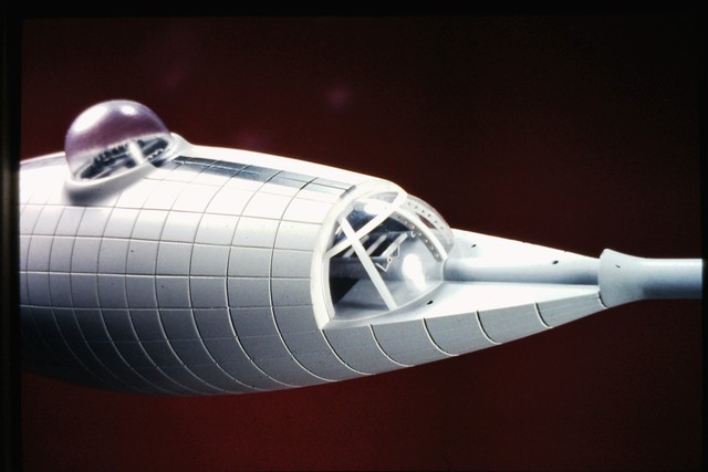
One last look at what can be made using the vacuforming process:
Nearly an entire model can be constructed of vacuformed parts. A filming miniature of this spacecraft, built for the movie, Flight To Mars, seems to have been pressed into service for just about every 50's science fiction movie. Obviously, hardware nerd that I am. Here's that work:
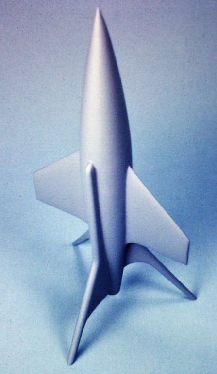
It took only three sheets of .060” thick polystyrene to come up with all the parts. The real work was cutting each part away from the sheet and sanding them for proper fit. Note the use of polystyrene discs within one hull half; there to strengthen and assure proper registration of the two hull halves as they were glued together with CA adhesive.
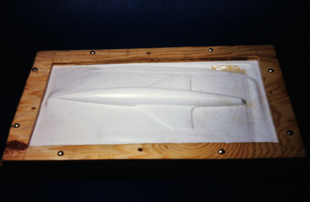
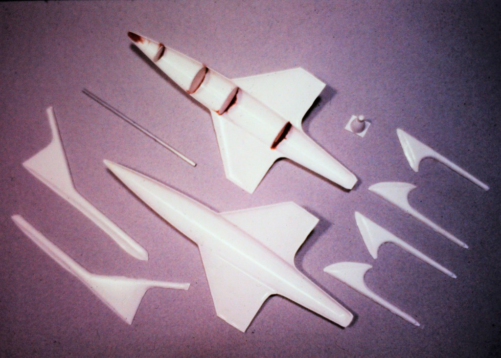
A submarines 'greenhouse'?
Well. For nearly three decades the incredible Ray Mason and I have talked about collaborating on a SEAVIEW model. Not the familiar one, but an r/c model representing the SEAVIEW as illustrated on the book-jacket below. The book a novelization of the movie screen-play.
Ray and I were captured by the allure of this unique departure from the vehicle popularized in the movie and TV series. Yes, we're both acknowledged leading lights in this game of r/c submarining – total detail freaks and gear-heads. This kind of project is the stuff that keeps miserable old farts like us young of heart, and still joyously in the game.
(I see you ducking for cover, Ray!)
Basically a tricked out SKIPJACK hull form with a ball-room sized, well glazed, Observation Compartment blended into the trailing edge of an enormous sail.
I bring all this stuff up to point to the fact that a pressure-proof, clear, practical, watertight structure like this can be achieved through the heat forming process.
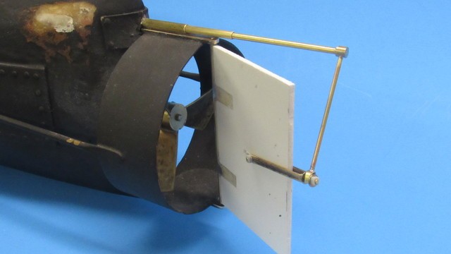
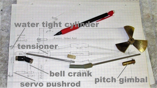

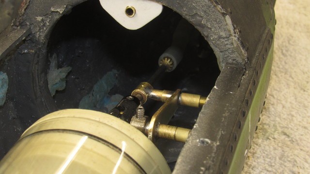


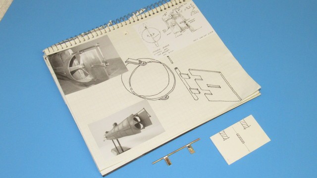

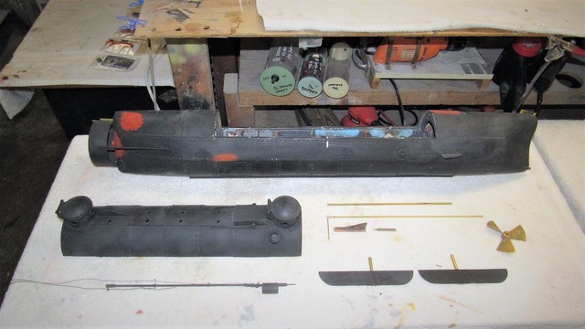
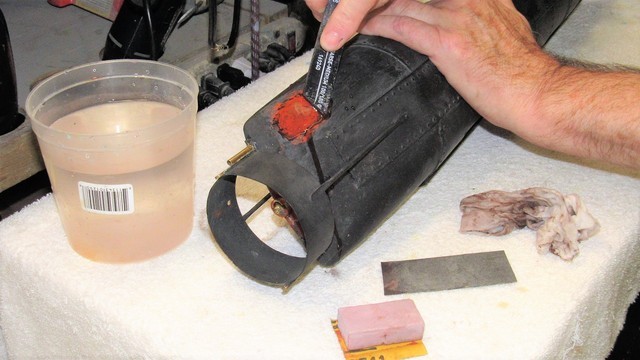
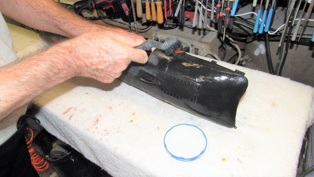
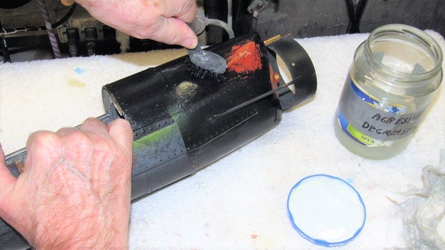

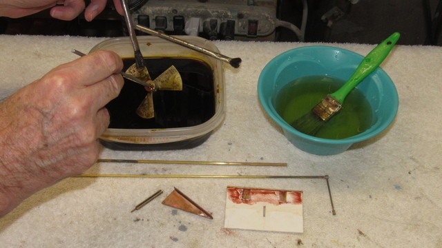
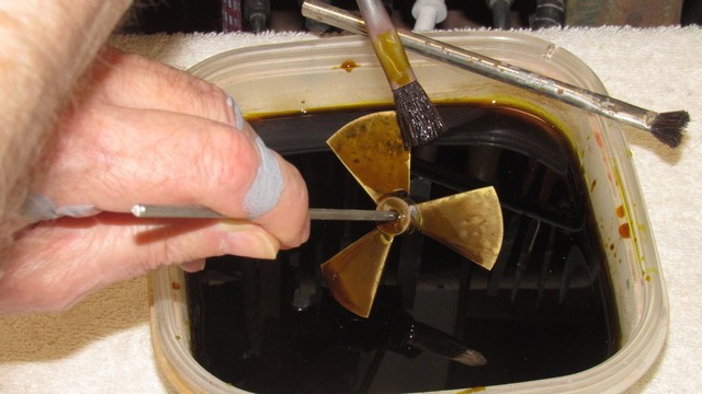
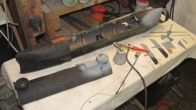
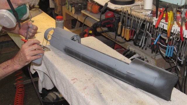
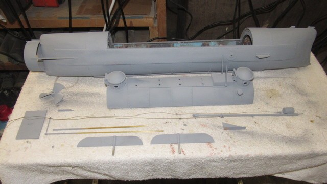
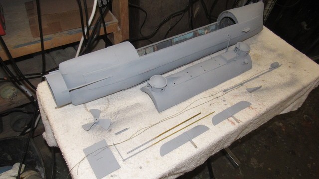

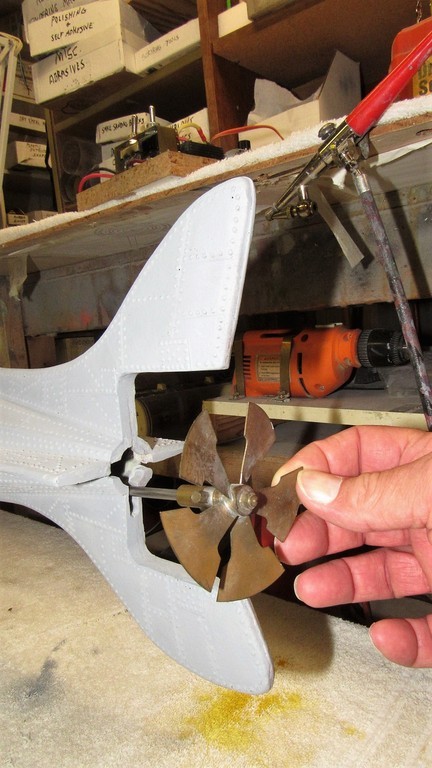
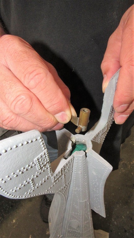
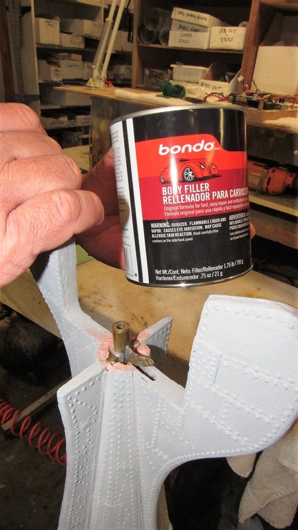

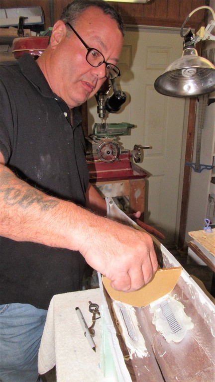
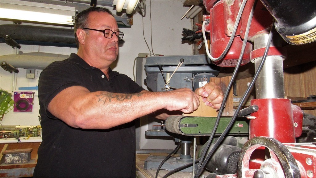


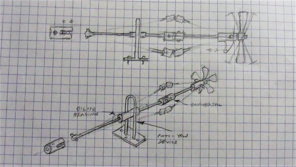
martinbayer
ACCESS: Top Secret
- Joined
- 6 January 2009
- Messages
- 2,374
- Reaction score
- 2,100
You, Sir, are a supremely powerful demotivator to the average modeler, for which I congratulate you wholeheartedly.
- Joined
- 18 March 2013
- Messages
- 978
- Reaction score
- 2,851
Damn right!... you common, mouth-breathing kit-assemblers tremble before my awesomeness and absolute command of the Newtonian Universe. Tremble in your corner or take my hand as I lead you to where the real model-builders hang out.
View: https://youtu.be/6emWN2tEPMk

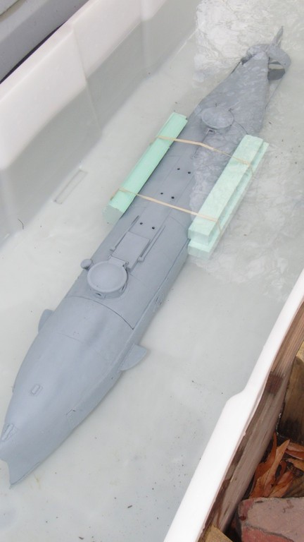


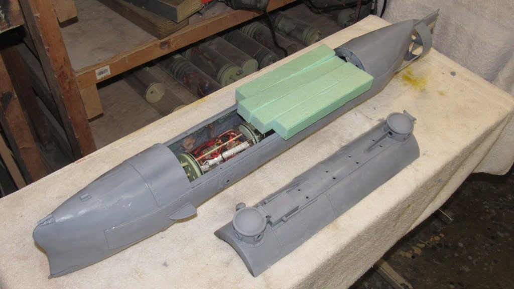
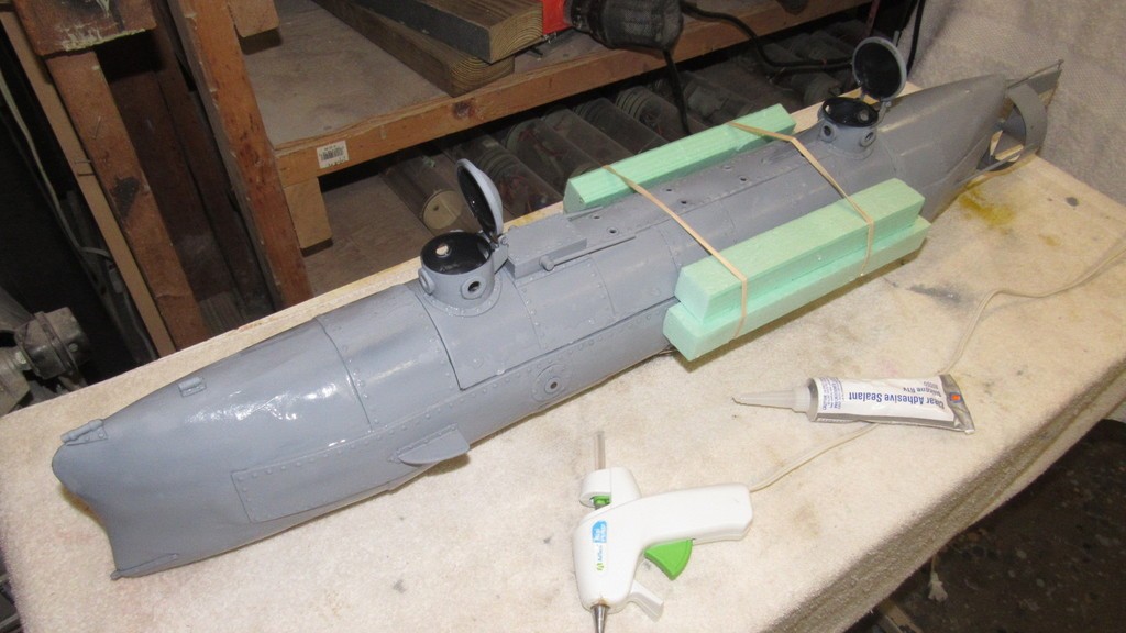


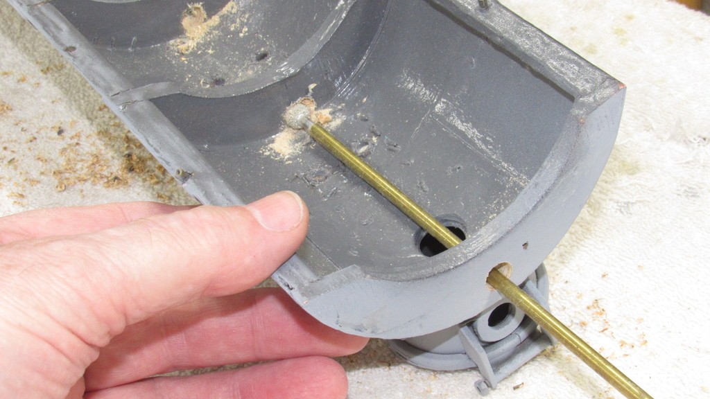
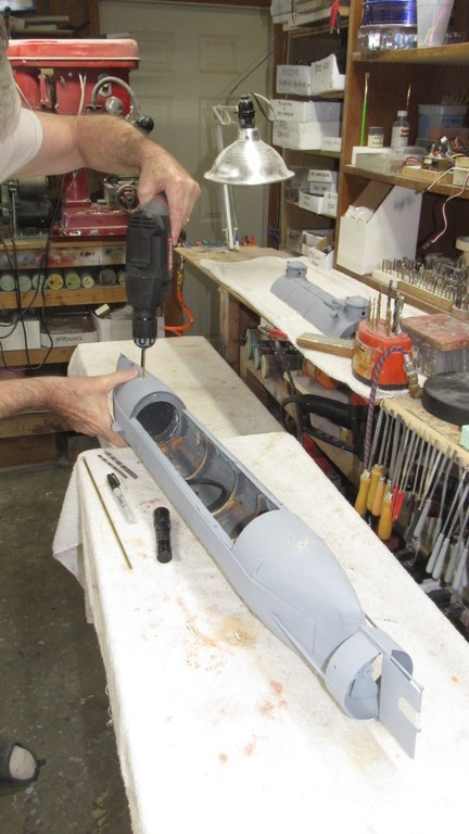
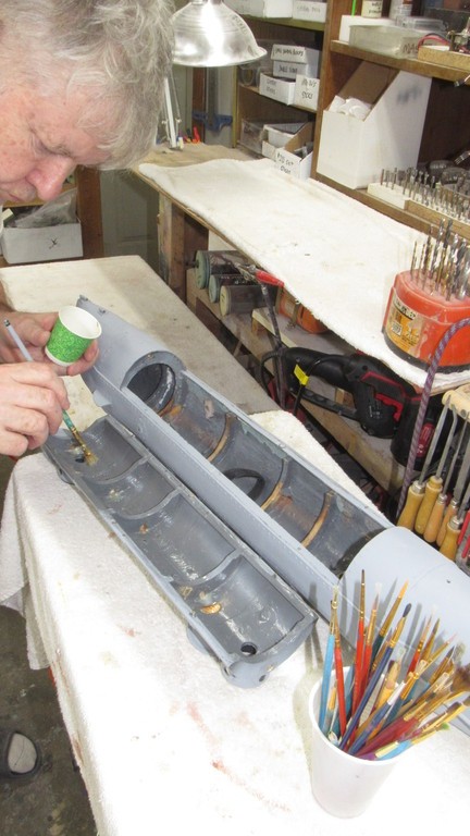
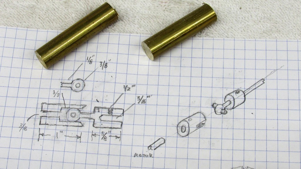


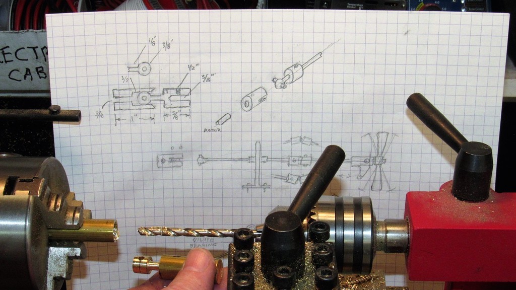
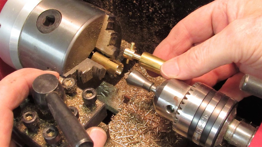
- Joined
- 18 March 2013
- Messages
- 978
- Reaction score
- 2,851
DEADLIGHTS
part-3
part-3
Transparent Plastic Inserts and Fiberoptics I've covered the two means I favor to produce thin walled transparent structures. Heat forming plastic sheet, and liquid-to-solid. But, in the majority of our work transparencies are rendered as either thick hunks of acrylic, cut from sheet or purchased as rod or square sectioned extrusions. The disadvantage of this type transparency is the inability to use it as a non-distorting lens to any detail built into the models interior; unsuitable for viewing the models interior, but excellent as a light focusing conduit when back-lit from within. Inserts are fine for projecting light to the outside world.
Typically a significant portion of the insert transparency resides well past the inside walls of the models structure. This to gather the rays of an internal light source(s), and project those light rays to the outside observe. A well lit model interior, as viewed through a deadlight; cockpit; port-hole; navigation light lens; search-light lens; astrodome, or any other type transparency – radiates light from the models interior through the transparencies.
This discussion deals with clear or colored semi-clear inserts. Their installation and use.
On this 1/187 Andreas Schmehl USS NAUTILUS kit, I initially intended to back-light the two lower sets of deadlights – as built the NAUTILUS had no less than three levels of deadlights at the leading edge of its huge sail!
Those two levels of deadlights started life as long inserts of .375-inches thick acrylic – you see those two blanks at the foot of the sail. I figured they would do a better job of catching an internal light-source than the epoxy liquid-to-solid deadlights at the upper row in front of the open bridge. Up there there's no room for any but a conformal liquid-to-solid transparency. Back to the inserts:
In order to evenly catch the light all internal faces of an insert were machined flat and sanded with #240 grit – the even, but rough surfaces, diffusing light evenly, presenting a uniform glow when back-lit, and not a random collection of disturbing hot-spots.
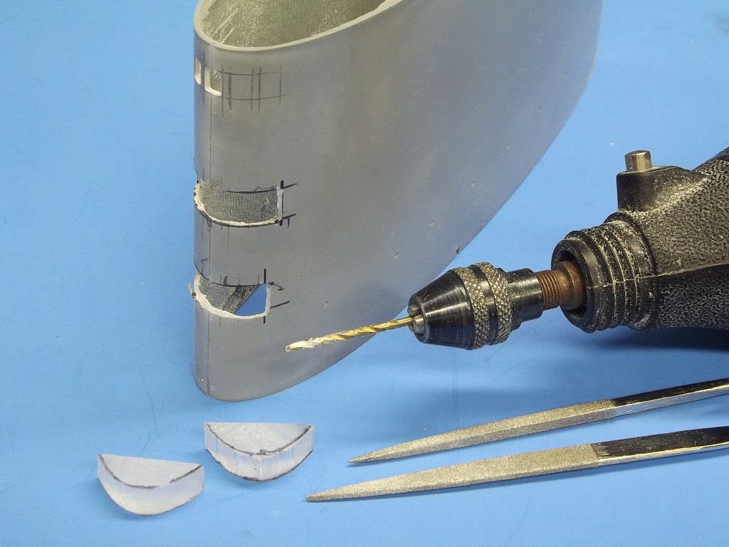
The two deadlight inserts, after being CA'ed in place, were filed and sanded down to follow the contour of the sails leading edge. To ease the later polishing task the outside surfaces of the faired in inserts were given several coats of CA to fill sanding marks or any open seams between insert and GRP sail. CA is clear, sets quickly, and takes to sanding and polishing just like acrylic.
The CA over-coat was then worked with descending grits of sandpaper, stopping at #3200 grit. At that point I continued with descending grades of liquid polish until the acrylic inserts were optically clear.
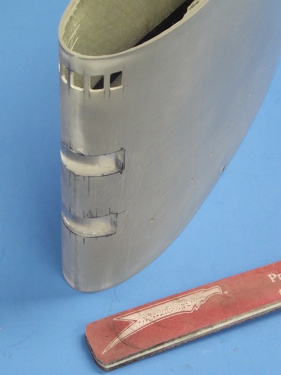
The deadlights are masked off and the first coat of primer goes down – this to better identify tool marks and open seams that were not adequately filled by CA or air-dry touch-up putty earlier. With the masking still in place problem areas were filled and sanded and spot primed. Once all surfaces outside of the masking were smooth and blemish free, the masking is removed and saved; as it needs to be used again later, as the model is painted and weathered.
That long strip of masking tape under the middle set of deadlights is there to insure that all deadlight masks are of the same height and spacing. It's removed before painting and priming.
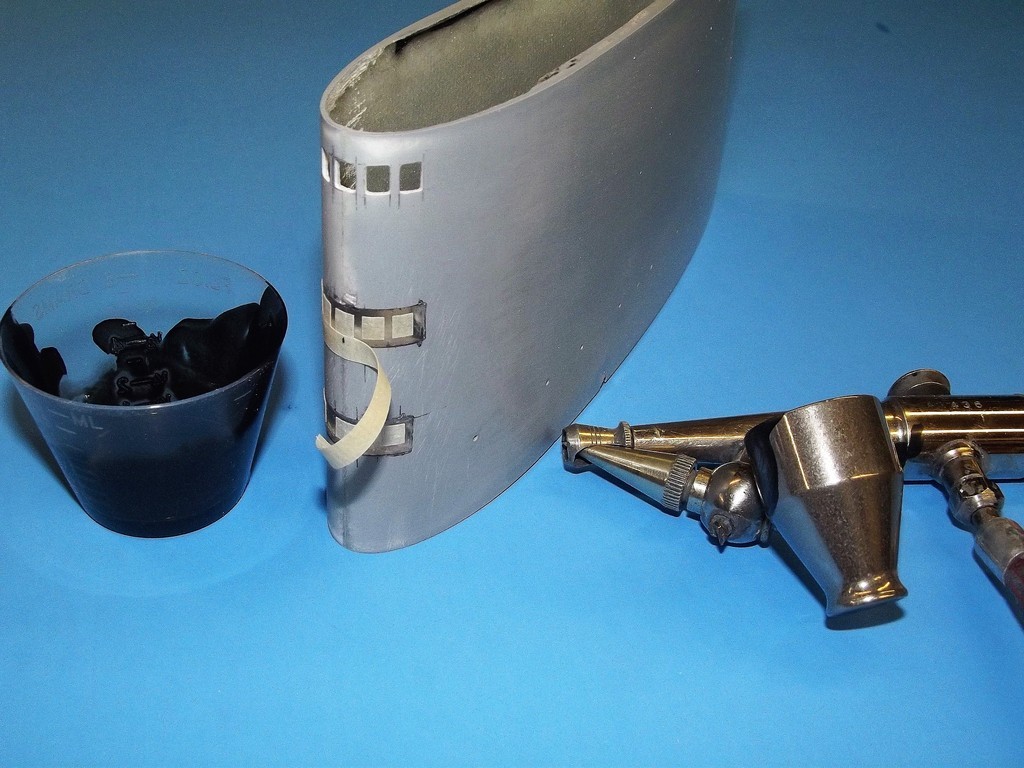
If the transparencies are to be back-lit it must be assured that light only is seen through the transparencies not portions of the model that are supposed to be opaque. Prevention and identification of light-leaks is the next operation.
The deadlight masking still in place, black paint is sprayed over the masked areas and over those portions of the hull where the light source is housed. The sure-fire way of finding light-leaks is to darken the work space, wait a few minutes so your eyes get 'night vision', then turn on the models internal light source and look for light leakage; light where light should not be. Repeated coats of black are laid down over the offending areas, and the test repeated till only the deadlights glow in the dark and nothing else.
It's a wise practice to retain the masks, as they will be needed later as the color coats and weathering are applied.
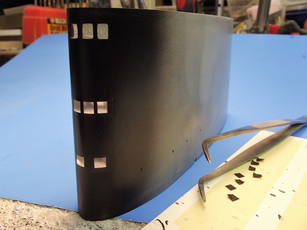
Acrylic round stock was used to form the deadlights within this commanders copula/access hatch mounted atop a 1/12 scale USS ALLIGATOR filming miniature we built for a TV producer who was working up an episode for the Discovery Science Channel.
The copula/hatch clear deadlights were represented by simply turning an over-size rod of acrylic to a diameter that made each transparency an interference fit to a port-hole; each end of a transparency polished to optical clarity; all made fast with a heavy coating of CA adhesive applied within the cupola/hatch.
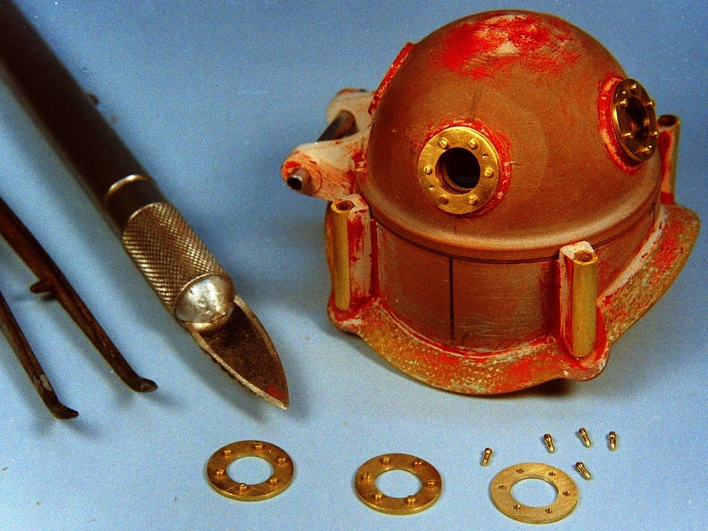
The ALLIGATOR effects miniature (unlike most effects miniatures) was an unrestrained r/c vehicle; free to maneuver in yaw and depth under radio control.
We were on set for a three-day shoot; most of it done at the David Taylor Model Ship Basin's enclosed maneuvering and sea keeping (MASK) tank and open-air explosive basin.
Here I've unceremoniously tossed the miniature into the MASK pool. (this is one of the facilities where Government Scientists and Engineers tests huge r/c models of surface and subsurface design articles).

The miniature being placed on the mark for another 'take'. Depth to the bottom on this side of the outside explosive basin was about 25-feet. Even at this relatively shallow depth most of the red from the spectrum has been blocked out by the water. If any dry space within the miniature was going to leak... this was the place for it!
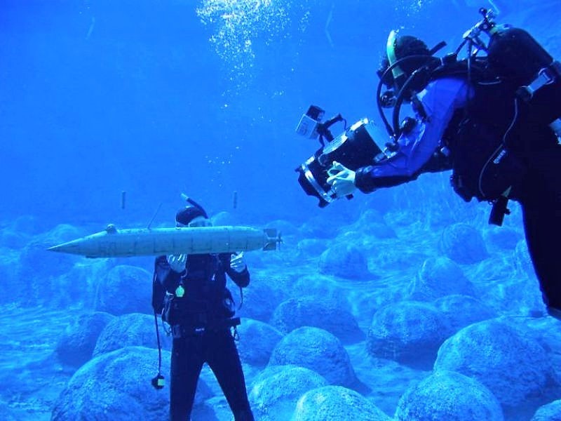
The ALLIGATOR's cupola/hatch and seating flange formed a watertight union and was subjected to about ten-PSI of water pressure during filming at the explosive basin. I was pleased to find no water had leaked into the cupola/hatch or WTC in the evening, as I performed post-mission maintenance and repair work.

Not only were the deadlight transparencies made watertight, so too were the practical cupola/hatch structure itself, as you can see here: The units hinge and locking dogs were practical. And a proper O-ring seal, set within the seating surface of the cupola/hatch -- insured a water tight seal when it was dogged down upon the flange.

It's good practice to have something interesting to look at on the inside of a structure featuring an optically clear transparency. In pursuit of that objective I sculpted a scale head and shoulder portion of Ab Lincoln. The Commander In Chief was positioned within the cupola.
(When I'm amused, I'm easier to work with).
The Director wanted the ALLIGATOR miniature to stand in as a proper display model in a scene where a historian addressed the audience as he viciously jabbed the model with a pointer, to accentuate his narrative about the Yankee submarines special features. (I think he was a Rebel at heart)
Hence the need of a scale Diver walking on the bottom, having just dropped out of the ALLIGATOR's lock-out chamber – further illustrating the unique capabilities of this Civil War era submarine.
Professional model-building is often more than model building!

Short lengths of acrylic rod were used to represent the four deadlights around the cupola/hatch as well the many deadlights that ran the length of the ALLIGATOR hull, port and starboard. Their function would have been to help illuminate the interior for the poor slobs hand-cranking the propeller or working the Diver's air-pump.
That period Diver fellow, taking a leisurely slogging through the river muck; on his way to perform some mischief against Rebel assets.
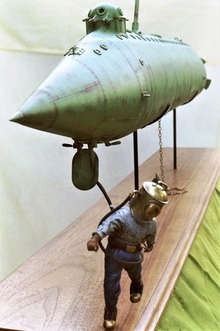
The guy holding the miniature – member of a team that usually is employed to work in the ocean, recording stuff for yet another, 'Shark Week' episode – is there to get the miniature positioned over its mark for a take, or bail me out if I loose control of the thing. Out of frame here, another Diver films the action.
(All joking aside – these guys were true professionals in and out of the water; things worked well on that shoot because of them. They knew their shit!)
Meanwhile.
I'm topside, standing dangerously close to the end of the pier, transmitter in hand, looking down, trying to get a bead on the miniature, and driving the damned thing as directed – deeper than I had ever driven an r/c submarine. All that going on as the Director screams stuff like, “Left turn!... I said LEFT TURN!... No!.. You're other left”. There were moments when I almost tossed him the transmitter.
No matter. We got the shots in.

Kit Enhancement with Transparencies The trailing edge of this Moebius 1/128 SEAVIEW kits sail was enhanced by adding two transparencies. The upper cavity to receive an emergency running light lens; the lower, longer opening was for a protective lens covering a stern-view CCTV camera.
I made use of the clear polystyrene parts tree that came with the kit – a 'runner', an element of an injection formed kit that gets the molten plastic into the tool cavities during manufacture. When you buy a kit that has clear parts, make it a habit to keep the clear runners for future use.
The stern light 'bullets' were turned from acrylic rod.

I roughed out the emergency stern light and camera lenses to the required shape before gluing them into their respective cut-outs in the sail. They were installed and made fast with CA adhesive.
Wherever possible make use of excess material as a handle as you shape, install and glue the transparency in place. The excess material is either snipped or sawed away and the rough-cut piece filed, sanded and polished to contour.

Movies don't get made until some wild-eyed Producer sells the story and outlines the mechanics of the production to the prospective studio and money-men. Sometimes, as part of the sales package, a models of vehicles and/or sets are elements of the Producers pitch. We've built a few of those.
This particular model, a concept of the still-at-the-time-confidential B-2 bomber, the subject of a proposed spy-thriller. So, this third-string, nobody, “Producer” contacts me, we come to an agreement, I build the model and send it to him. He disappears.
We never got paid for the work. Ellie was not amused!
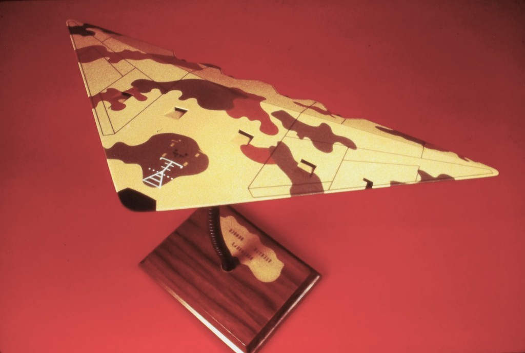
Construction was easy as the entire form of this B-2 was flat planes of polystyrene sheet with only the tips of the wing and nose radome describing a curve, everything else was hard-edge. I was working off an illustrated magazine article, so I assume the artist was thinking of the faceted, very ugly F-117 when he dreamed up this fictitious B-2 bomber.
As the model was too small to represent a cockpit I simply painted the bottom of the inserted acrylic piece gray and left it at that. The acrylic transparency was dropped into a cut-out atop the wing, glued, and faired in smooth with the surrounding surfaces. Masked off, I proceeded with the funky 'desert camouflage' scheme the Producer wanted.
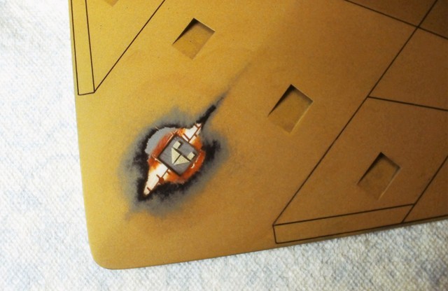
Back-lighting transparencies It's one thing to let ambient outside light sources kick around within and behind a transparency, the effect is usually pleasing and reads to the casual viewer as 'real'.
But, its a different game when the transparency is back-lit; where the light source is from within the model – the objective, most of the time, is to achieve an even glow over the entirety of the transparency.
Back-lit transparencies are either microscopically scratched/pitted or given a very flattened clear-coat on their inboard faces to present diffused light, not an interior.
This 58-inch DeBoer Hulls SEAVIEW model features back-lit transparencies as described above, but also features the big bow, optically clear, windows of the observation compartment with all its interior detailing – in that situation internal lights, themselves hidden from view, illuminate and present internal details of the model.

The actual effects miniatures from the movie and TV show had practical running lights on the sail, but they were white. The sailor in me just had to make them a proper green on the starboard side, and red on the port side.
The 58-inch long SEAVIEW was a perfect candidate for use of unaltered LED's of the appropriate colors sticking out the sides of the sail.

At the bow there was the forward search-light; the port bottom-illuminating lamp; and its counterpart on the starboard side. All three were back-lit from 12-volt car turn-signal incandescent bulbs – chosen for their exceptional brilliance.
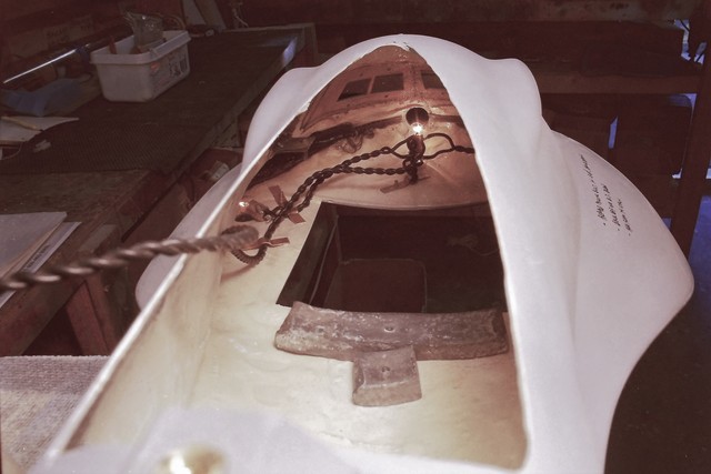
Demonstrating the brilliance of the search-light and bottom-illuminating lamps. All three lenses were turned from acrylic rod.
I'm holding the sail running lights. Note the current dropping resistors, needed to limit current flow into the LED's to less than 2mA.
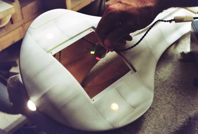
Small grain-of-rice sized incandescent bulbs represented the SEAVIEW's stern lights.

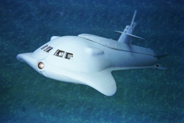
UQC intercept:
“Admiral Nelson to pursuing UN submarine: Disengage! Or soon discover your actual Design Depth... continue to follow at this descent rate and you'll find out, fool!”
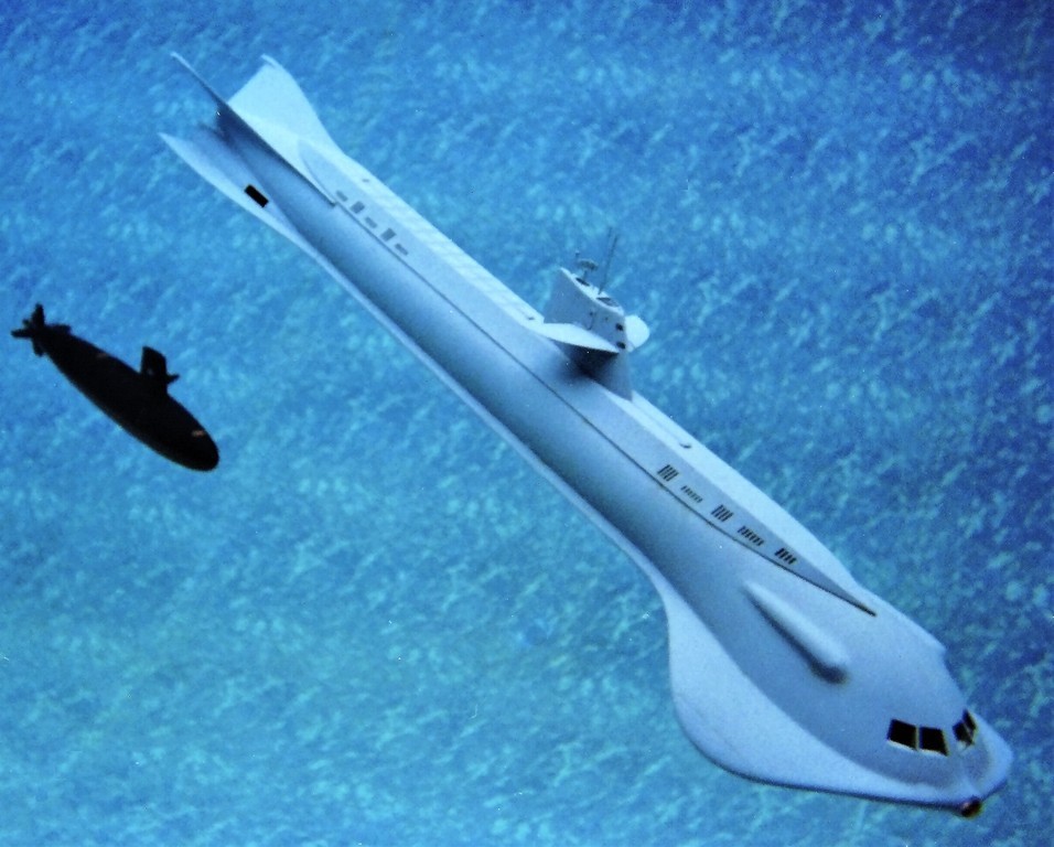
- Joined
- 18 March 2013
- Messages
- 978
- Reaction score
- 2,851
DEADLIGHTS
part-4
part-4
A welcome departure from the ill-fated ENTERPRISE job was installation of a single white identification lamp just forward of the access hatch atop the sail of this 1/12 scale KAIRYU, WW-2 era Japanese coastal defense, two-man submarine. The single lamp used only during training, identification, or retrieval.
The operational profile of these little submarines was a simple one: they would operate for only one sortie. Because of a shortage of the planned torpedoes, these submarines would, instead, engage Allied amphibious forces as explosives laden suicide craft.
Thank goodness for the atomic bombs!
(My dad was training for his role in the invasion of the Japanese home islands When several pounds of fissionable metal halted the war).
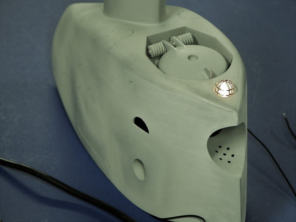
For the model a miniature grain-of-rice sized incandescent bulb was housed within a turned acrylic rod that represented the actual boats waterproof lens, which was protected by a metallic 'cage'.

Surprisingly, this model became my go-to vehicle for towed camera jobs owing to its long horizontal stabilizers and small screw. The tow-line seldom got entangled in the screw, and the boats ability to turn and hold commanded depth is exceptional. You can see it in action during the later portions of this video:
(starts at 52:00)
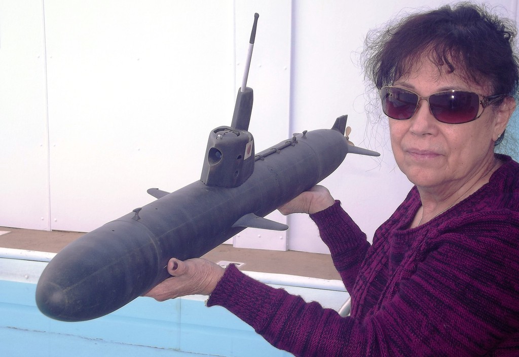
This 1/96 Thor SEAWOLF model featured sail mounted port and starboard running lights. The two colored transparencies (green for starboard, red for port) were back-lit by a single common incandescent bulb within the sail.
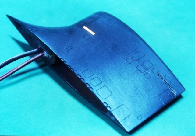
As is my practice on any model that will be lit from within I paint all the opaque areas black, darken the shop and after my 'night-vision' has kicked in the back-light(s) is energized, and the surface of the model checked for any light-leaks. Once any problems are found and fixed, the model is given the first color coat (for modern submarines, the topside areas are a very, very dark gray).
As color tinted sheets and extrusions of acrylic are hard to find I often resort to using the handle portion of an appropriately colored tooth-brush, cut to shape and inserted into the model to form the semi-transparent colored lens.

An anchor-light atop the SEAWOLF's upper rudder was a grain-of-rice incandescent bulb. Its wires running down the hollow rudder operating shaft.

This Thor 1/72 ALFA model also employed semi-transparent tooth-brush colored lenses to represent the port and starboard running light lenses. Using the unused portions of the tooth-brush as a handle, it's an easy matter to cut the end to the desired rectangular shape. Snipping the rectangular pieces off when brought to proper shape.
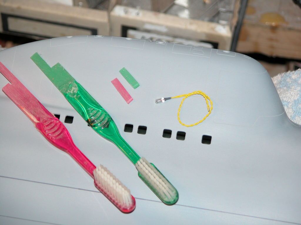
Incandescent grain-of-rice bulbs were used to represent the stern and anchor lights, both affixed to the ALFA's upper vertical stabilizer.
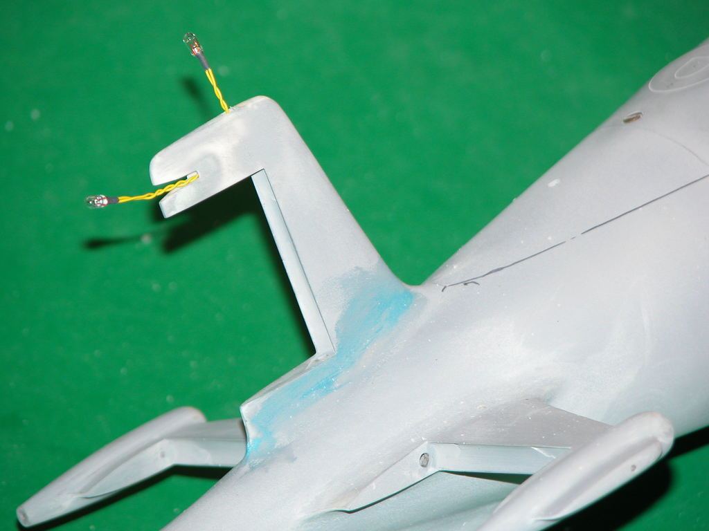
A single incandescent bulb, the mast head-light, was fit atop the ALFA's sail.
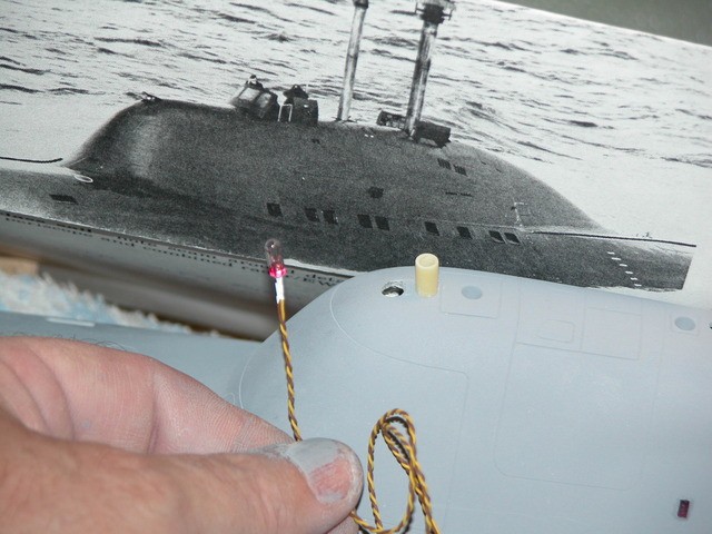
Ellie holding the completed ALFA model.

The 1/72 ALFA making this pool safe for Communism.

The only movie Ellie and I secured screen-credit on was a horrible little slasher SF thing called, Midnight Movie Massacres (AKA Attack From Mars).
Though we had done work for such productions as The Hunt For Red October, Crimson Tide and several ST properties our anti-union position and status kept any acknowledgment of our work off the big-screen.
We not only designed and built the effects miniature, we spent two weeks at the Missouri studio to rig and 'fly' the miniatures as well as building two forced-perspective miniature sets. Hell!... Ellie even fabricated a 15-foot long nose booger (don't ask).

We were involved from the beginning of the production, working off the initial screen-play I story-boarded all scenes featuring a miniature. From those illustration the size and capabilities of those miniatures was established. All of the work being done in the garage and back-porch of our Navy housing apartment!
The smallest miniature was a weird looking 'bad-guy' spaceship with round port holes that had to be back-lit to glow brightly. The body and fins were made from polystyrene foam and then overlaid with epoxy saturated fiberglass cloth.
Here's that miniature just before installing the acrylic rods that would form the port-hole transparencies.
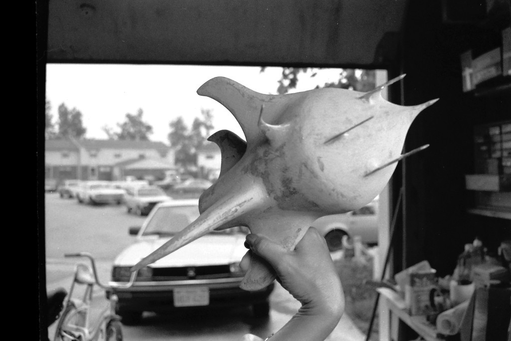
This miniature started life as a lathe turned hunk of polystyrene foam – that specific type expanded plastic selected, as the requirement was to skin it with resin saturated glass cloth then dissolve the foam core away to render a hollow GRP model.

The 'fins' and other appendages were made up to the hull after it had been skinned with GRP. Here are foam blanks of those fins fresh from the band-saw. A foam-rasp and #38 sandpaper got them to shape quickly, after which they were epoxied to the hull at random locations, and GRP skinned – the objective was to give an asymmetric, unearthly, appearance to the miniature. The polystyrene foam hull blank is to the right, ready for turning.
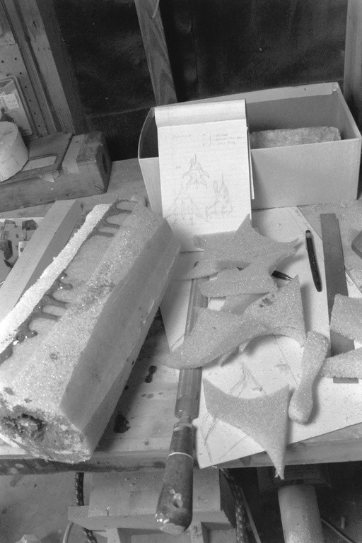
After laying down several laminates of epoxy saturated 10-ounce fiberglass cloth to the hull, gasoline was poured into the nozzle end of the hull, quickly reducing the rigid polystyrene foam to a goo that was poured out leaving a hollow GRP hull.
This 'lost foam' technique achieves a hollow GRP hull without going through the classic pattern-tool-part process; a quick means of fabricating a one-off item.
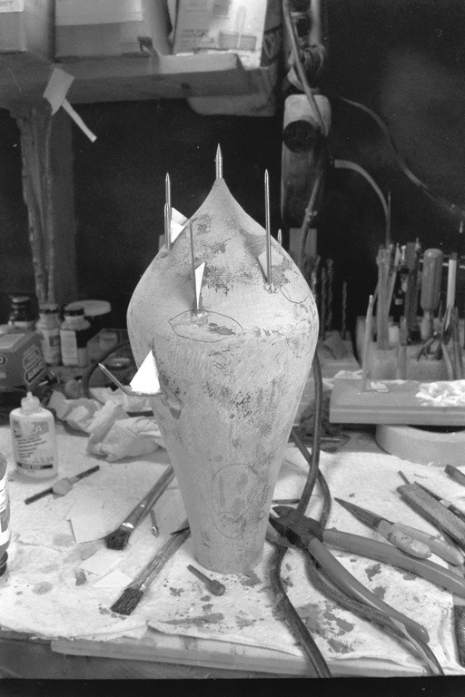
As all transparencies would be circular port-holes I selected a variety of acrylic rod diameters and inserted them into random holes in the miniatures hull, securing them with CA adhesive. Here I'm grinding excess acrylic down to the surface of the hull.
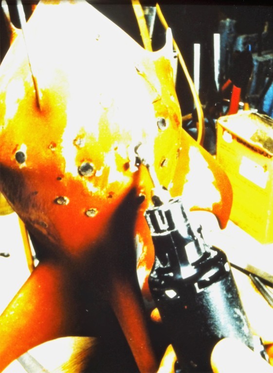
Before painting the bad guy spaceship I lit it up to find the light-leaks. Masking was reapplied in those areas that leaked, and more primer was sprayed over the offending portions of hull.
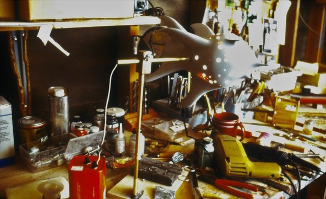
The completed 'bad guy' spaceship undergoing a last lighting test while mounted on the shop pipe stand. Note that the pipe supporting the model acts as the conduit for the wires that energize the single bulb suspended in the middle of the hollow hull.
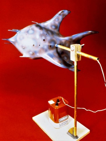
The biggest effects miniature we made for this flick was a tear-drop shaped mobile space-station model. A hollow GRP structure it was festooned with hundreds of port-holes, all back-lit from an internal source. The forward portion of that miniature mounted on its pipe-stand as Ellie drills out holes for lengths of acrylic rod.
Some of the round acrylic rod projecting into the hull can just be made out in this shot. The after, removable 'stinger' section of the miniatures, which permitted access to the two florescent light sources within, is out of frame. The temperature of that light, captured by the acrylic inserts, would evidence as a bright green glow seen through the round, polished 'port-holes' laying flush with the outer surface of the model.

This part of the work was laborious! A row of holes would be drilled; then take a break from that by snapping rod and inserting the pieces into the holes; slather on some thin formula CA, and saw each one off just a fraction of an inch proud of the models surface; then get back to punching more holes.
Once all the inserts were in pace a belt sander ground the rod down to a point where only a very small amount of transparent rod projected above the surface of the hull. The rods were brought flush to the hull with a sanding block.
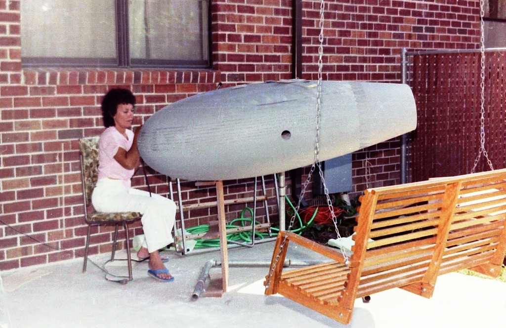
As this miniature represented a mobile space-station over a thousand-feet in length it was outfitted with numerous small bumps and nondescript shapes to suggest the massive size of the 'real thing'. With the stern 'stinger' attached, this miniature was effects miniature was about seven-feet long!
I'm loath to just tack down random kit parts (which had been rage in the industry since 2001 A Space Odyssey). We don't do that! Each and every part added to this big miniatures was vacuformed from dedicated patterns.

Preparing the big space-station miniature for its first light-leak test. The stinger is secured temporarily prior to the test. It would be glassed in place and the seam totally erased later as we got to the painting stage. Just above the pipe-stand elbow you can make out the extension cord that leads from the internal florescent bulbs to the outside world.
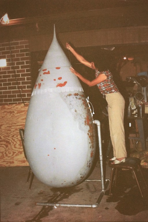
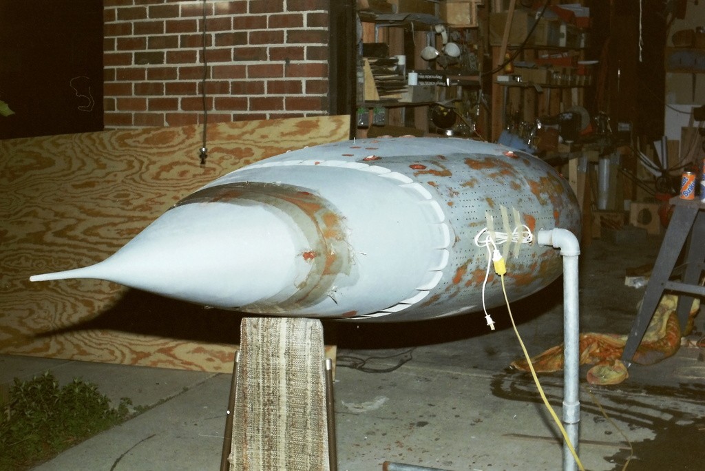
The completed space-station miniature at the Missouri studio (an old Masonic Temple) in our assigned work-space, the ball-room kitchen. For two weeks Ellie and I tended to and operated the miniatures. We were pulling eighteen-hour days, but it all was the adventure of a life-time.
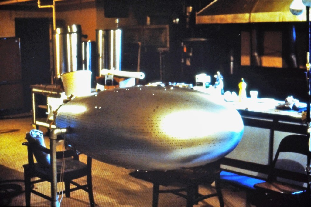
One story element of Midnight Movie Massacre dealt with a time machine. In the shape of a classic flying saucer. My story board cells called for this thing to 'fly' using a wire suspension rig. Here you see the completed miniature, about five-feet in diameter, hung from the garage girders, being tested before being crated up and sent to Missouri.
Power for the back-lit lights near the center bottom of the craft came down through two of the four suspension wires. The transparencies, like those of the space-station, were short rods of acrylic back-lit from within. In this case three very bright incandescent bulbs.
Does this saucer look familiar? Check out the saucer shown in the opening credits of, The X-Files.
(By the way, that's the 17-foot SEAVIEW miniature in the background... we were busy little beavers in the mid 80's).
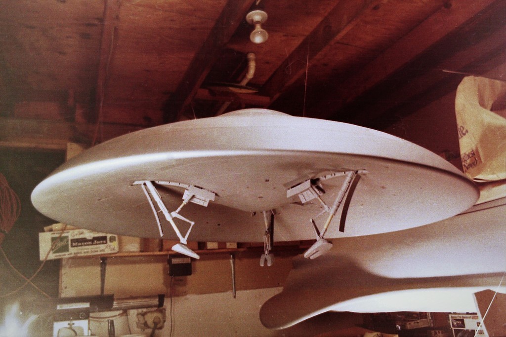
The labor intensive chore of installing hundreds of dedicated transparencies into an opaque hull was eliminated by the Industrial Light and Magic (ILM) crew as they worked up the miniatures for the (then) new Star Trek series, Star Trek The Next Generation – Those guys, the cream-of-the-cream in the model-building game, simply made the entire miniatures hull transparent; or at the very least, semi-transparent. With a semi-transparent all all that is needed after the lay-up and polishing is simply to apply laser self-adhesive masks, paint the thing, pull the masks, and job done. I simplify, but that's the gist of it. Pretty damn slick!
The models outer structure is GRP, the laminating resin is clear and the glass weave of the laminates becomes semi-transparent when saturated with the binding resin. Below is the result. This shot of the big ENTERPRISE-D 'hero' model.

ILM got the ball rolling on that series. Later miniature work was farmed out to Greg Jein's outfit. Ellie and I already had a professional relationship with this guy, the best free-lance model builder in the game. Through the course of the show Greg contracted with us to build masters of just about every 'warp engine' sub-assembly seen on the little-screen.
For example, this finished Klingon ship, nearing completion at Greg's shop featured warp-engines that started life in our Virginia Beach garage as masters from which his guys made tools and transparent parts that would be back-lit, like you see here.

After a script was approved by the studio, Greg was usually given only weeks to build the required miniatures, that kind of squeeze necessitated the engagement of third-party contractors like us. Just more balls added to the ones he was already juggling.
For this particular job he tasked us to also produce the rubber tool his guys would use to make the translucent warp engine bodies. Here's the completed Klingon warp-engine mounted on mold boards with their associated containment dams ready for the first pour of room temperature vulcanizing tooling rubber.

We eventually got so many of these quick-and-dirty pick-up jobs for STTNG that Greg threatened to send us matching crew T-shirts and ball-caps emblazoned with the Paramount logo and big letters spelling: WARP-ENGINES R' US. (Still waiting!)
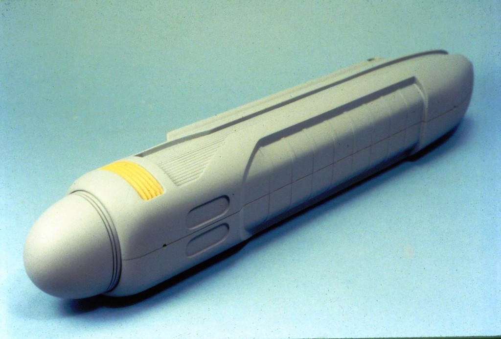
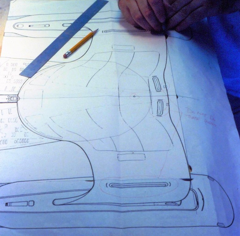
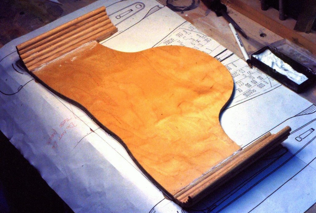
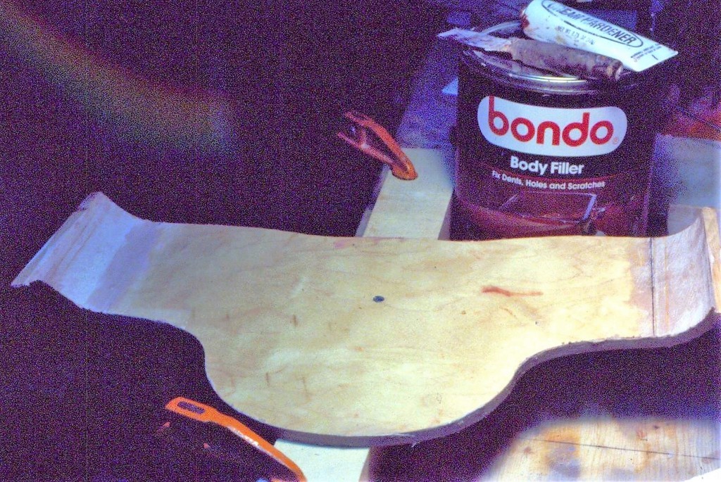

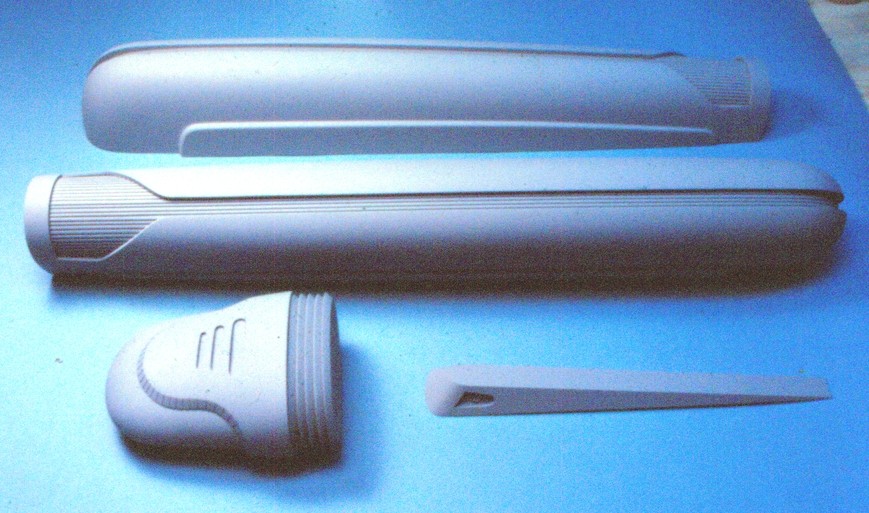

Transparencies within transparencies.
This display model was commissioned by a defense contractor that was selling fiberoptic data buses and multi-task, sit-down and stand-up information display and control consoles. The client provided the documentation and directed us to build a model display that represented some of their product as it would be applied to the Royal Australian Navy's (RAN) COLLINS class submarines. The result was this rather large cut-away of a COLLINS control-room.
I later learned that heads rolled when the display was presented at a defense convention. Apparently a RAN liaison or Australian government official was browsing the booths when he came across the model. He observed that the display contained 'confidential' elements.
Something went down; we never heard from that client again.
Where was I? Oh, yeah... back-lit transparencies.
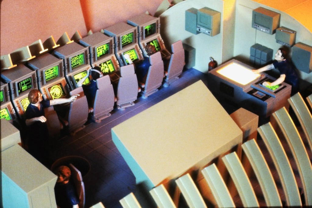

Seven multi-task sit-down station cathode ray tubes (CRT), and the stand-up dead reckoning trace (DRT) navigation console CRT were back-lit to project ship and environment displays to the operators and conning team. That was the emphasis for this display – to show off our clients hardware in model form.
Here I'm showing how these cast resin sit-down multi-task console models went together, and how LED's back-lit technical display transparencies.
To prevent 'hot-spots' on the CRT displays I placed cotton and a sheet of translucent plastic sheet between the LED's and transparency – these interface items worked to evenly distribute the back-lighting across the entire face of a transparency.
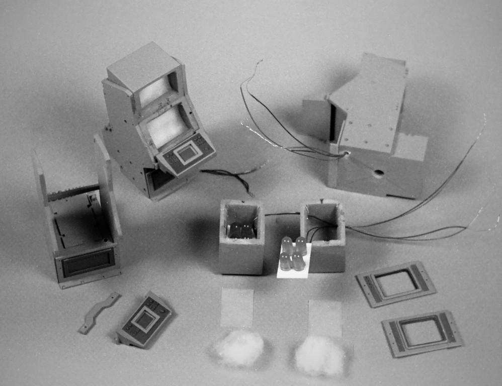
Each display transparency was a frame of exposed and developed 35mm black-and-white film. Film I shot with my camera of documents provided by the client (those documents possibly the source of the above brou-ha-ha).
All but the chart back-lighting was hooked up to a 555 timer chip to produce a 'flicker' effect – an artifact of the old CRT technology. A barely perceptible dynamic that helped breath life into an otherwise static display.
Hey!... you do what you can to make things interesting; things that catch the eye of the government appropriations people as they migrate from booth to booth (after tanking up at one of the many convention 'hospitality suites'). The Stories Ellie and I could have told!

This big stand-up console is the Navigator's dead reckoning trace (DRT).
(A system that provides the Quartermaster's the ability to estimate the boats position by integrating course, speed and time – own ships position displayed as an illuminated moving dote under a chart representing the area of operation).
The big opening will receive an array of incandescent bulbs that will back-light a chart.
The smaller opening, back-lit by green LED's, represents another multi-task CRT display.
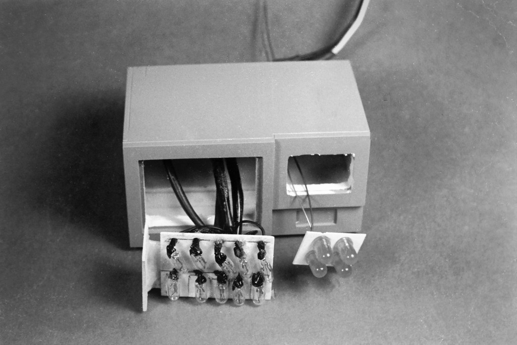
The DRT in action. Can't make out the chart overlay because of the long exposure needed to make the shot. However, the detailed navigational chart being back-lit by the array of incandescent grain-of-rice bulbs (and thank goodness the client never checked) is a topographical map of our Virginia Beach r/c boat clubs favorite play-ground, Lake Trashmore.
To keep from going insane, pro's will take every opportunity to sneak in little (and sometimes not so little) Insider gags the client won't catch but would be appreciated by other pro's in the know. It's a game we played. There are famous/infamous examples of this:
Greg Jein's crew festooned the Close Encounters of the Third Kind, Mother-Ship with little mail-boxes, an R2-D2, and crew names spelled out in port-hole lights; the smaller, The Abyss OHIO class submarine miniature had a screen door on the non-filming side of its sail; the Disney NAUTILUS hero model had 'goff' spelled out in rivets on one side; I stuck Ab Lincoln in the cupola of the ALLIGATOR effects miniature; and panel lines of the hero ENTERPRISE-D miniature spelled out, 'FU'. Long hours in the shop exacts a price.
And I went a little nuts on this job too.
The COLLINS control-room back-lit displays had more than one gag; a wrench teetering at the edge of a cabinet directly over the Navigator's head ready to clonk him the moment the boat took a down-angle; a drip-pan with loose tools in it way behind the radio-crypto-room enclosure; and a rather racy Playboy pin-up hung on a cabinet next to the ship-control station (Ellie was not amused – it came down within seconds of its going up).
Fun and games in the wee morning hours with a deadline just around the corner.
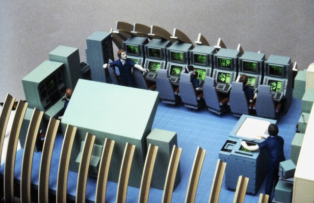
Last edited:
- Joined
- 18 March 2013
- Messages
- 978
- Reaction score
- 2,851
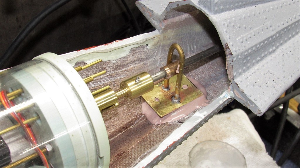

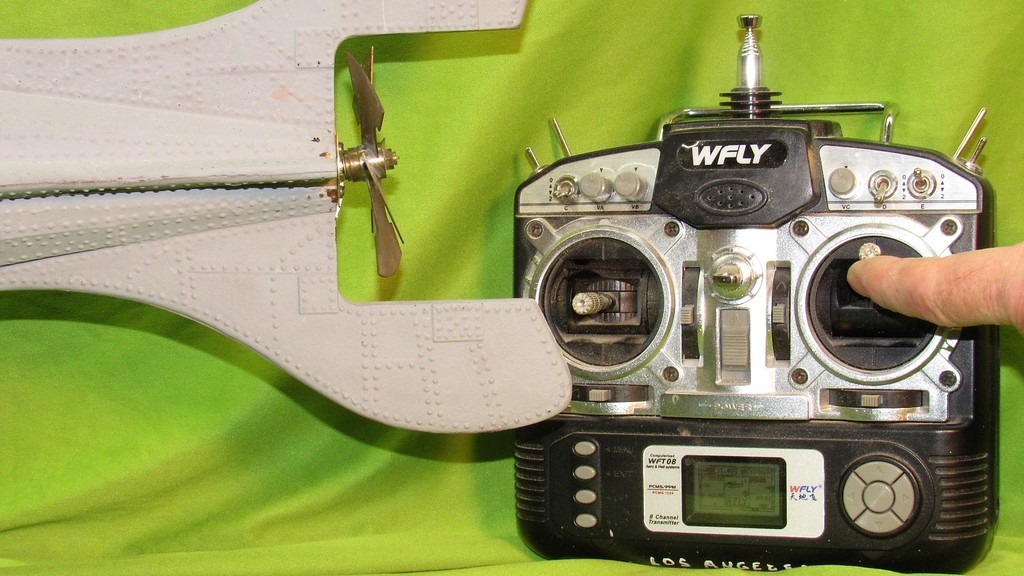
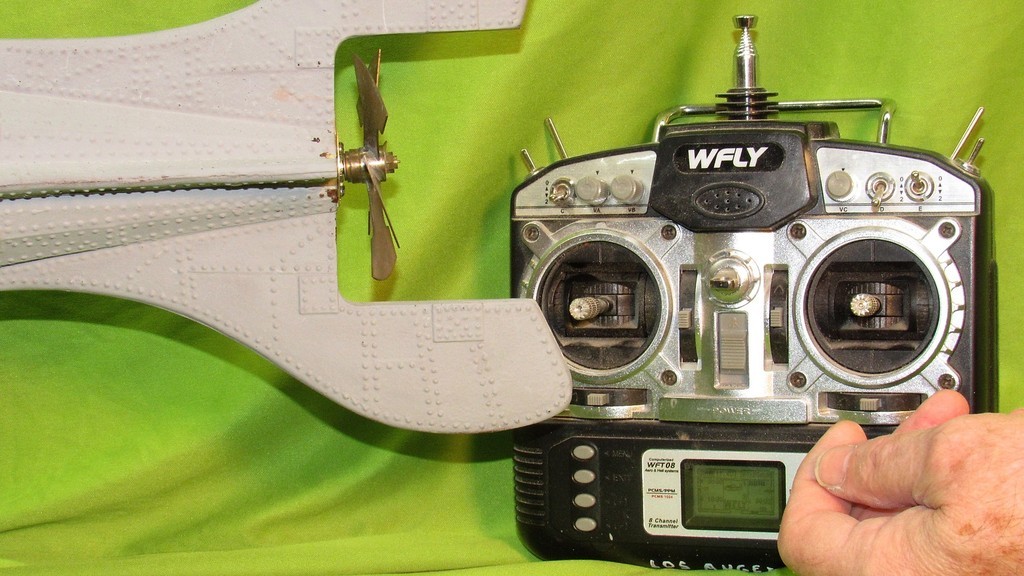
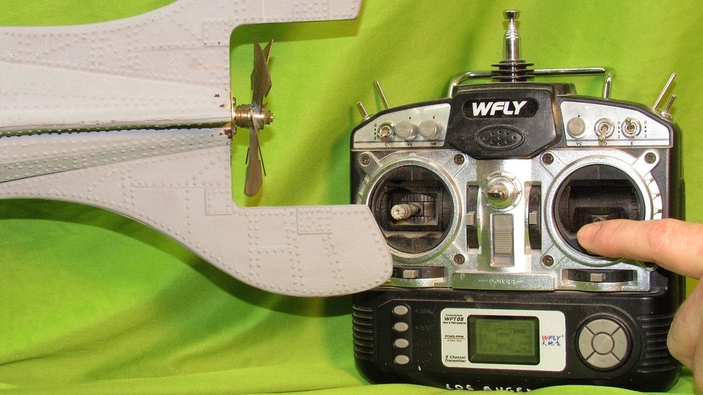
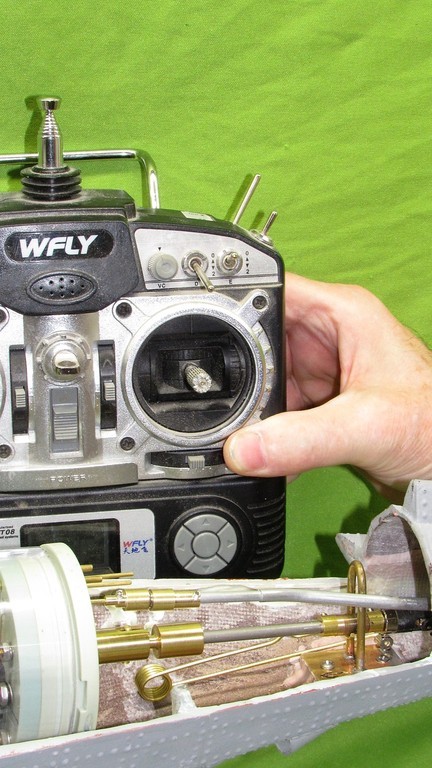
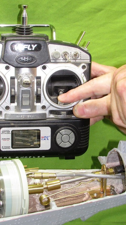
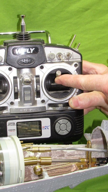

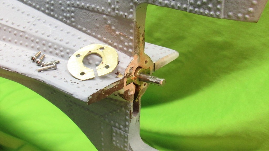

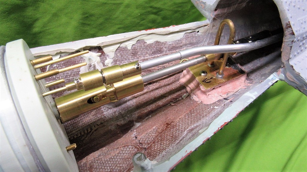


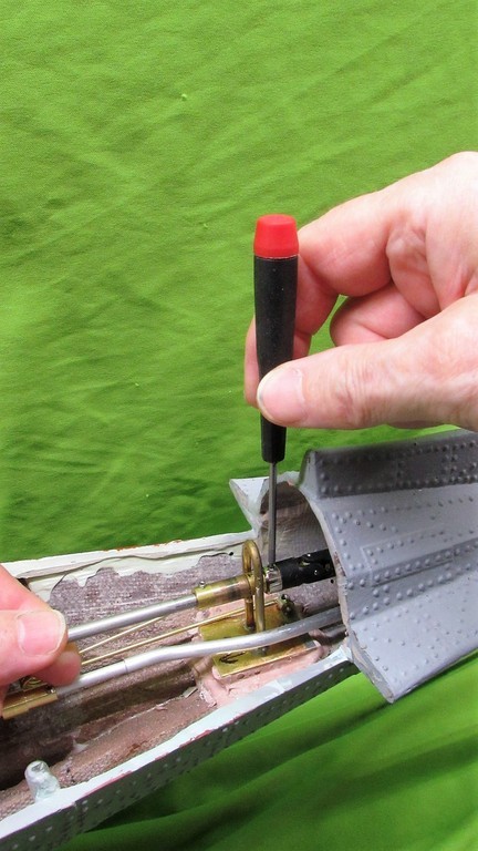
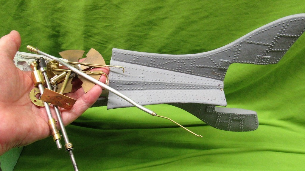


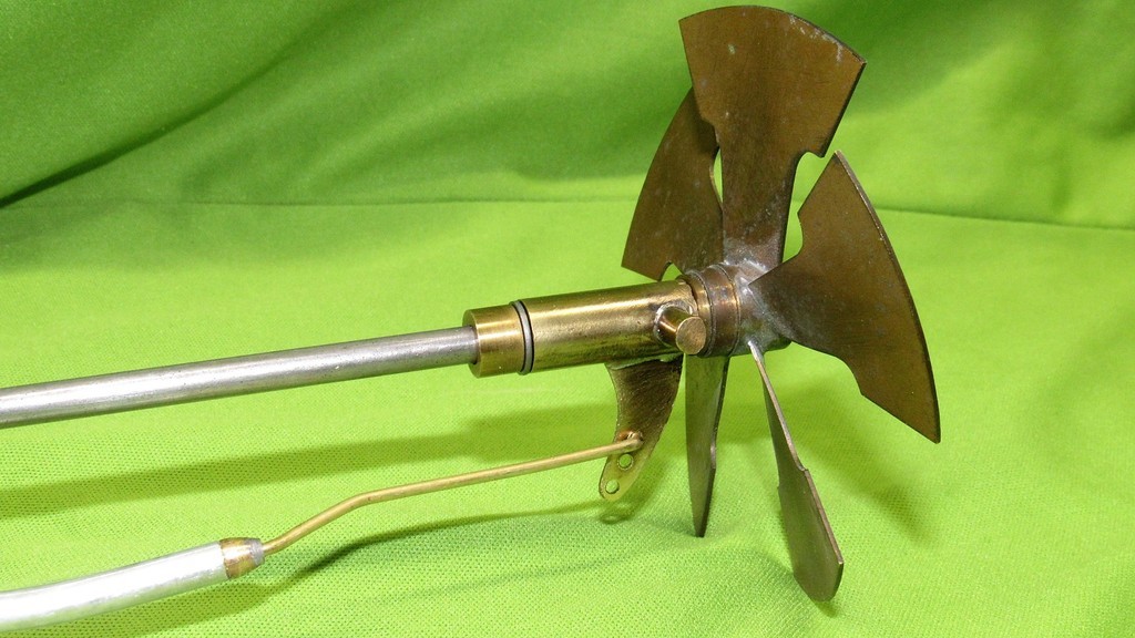
Last edited:
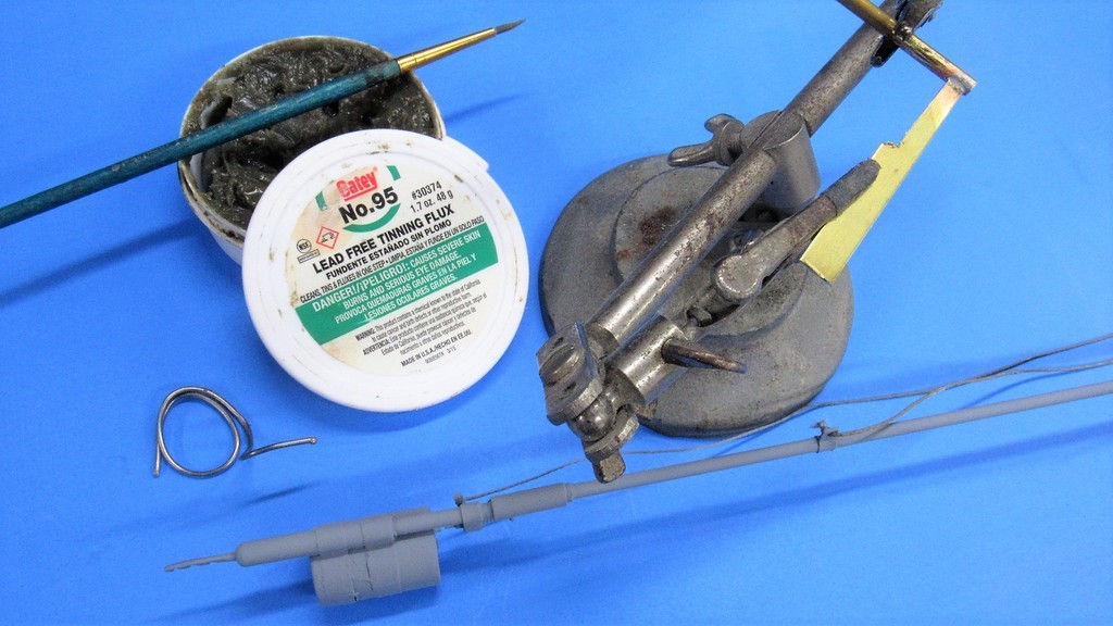
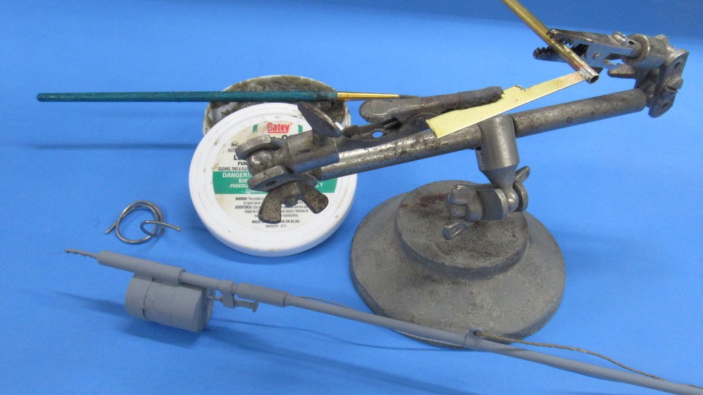
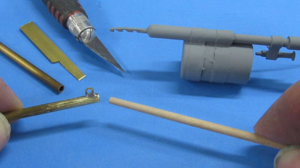
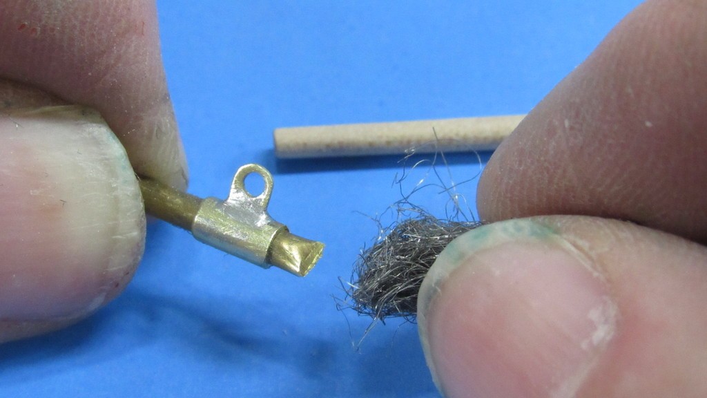
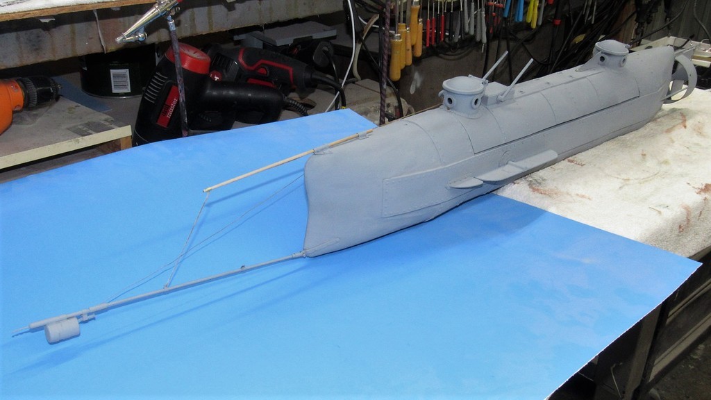
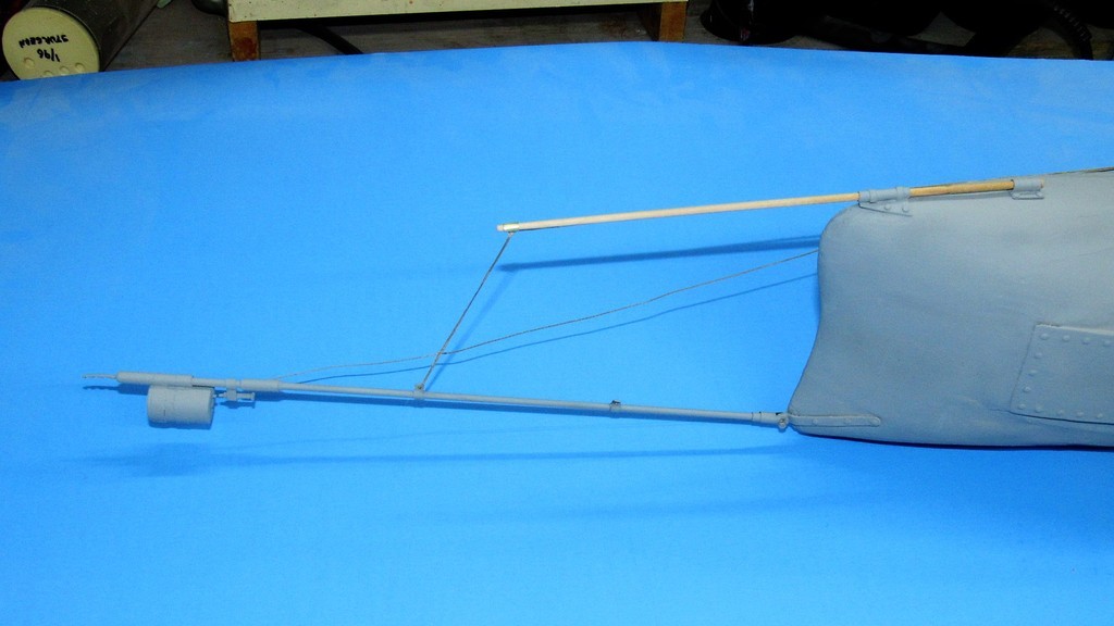


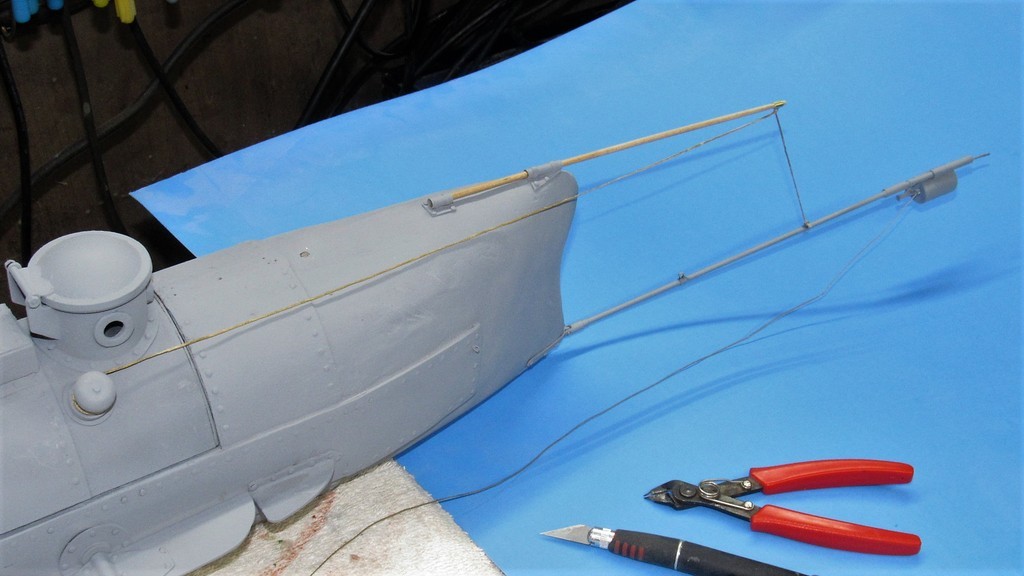
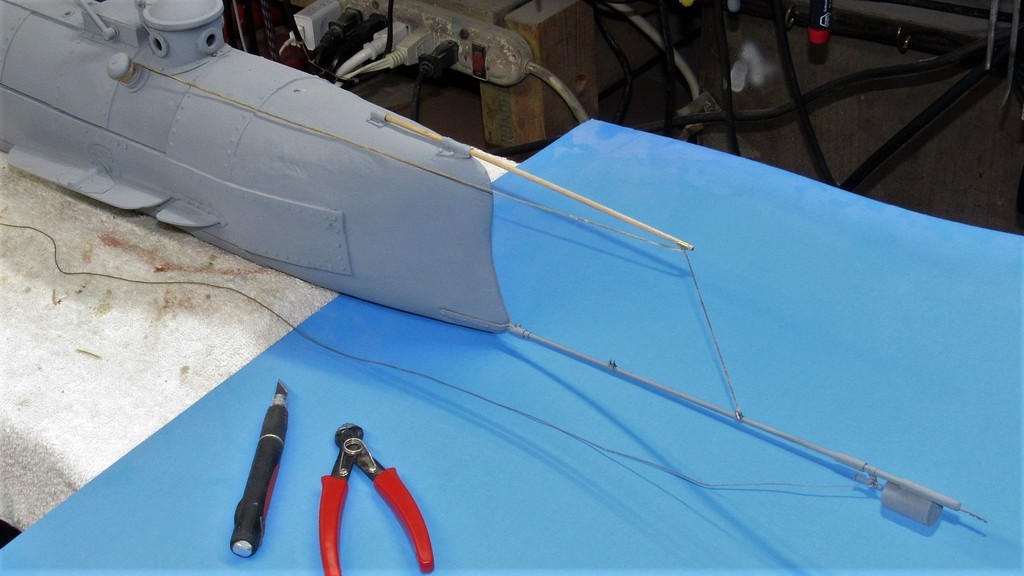
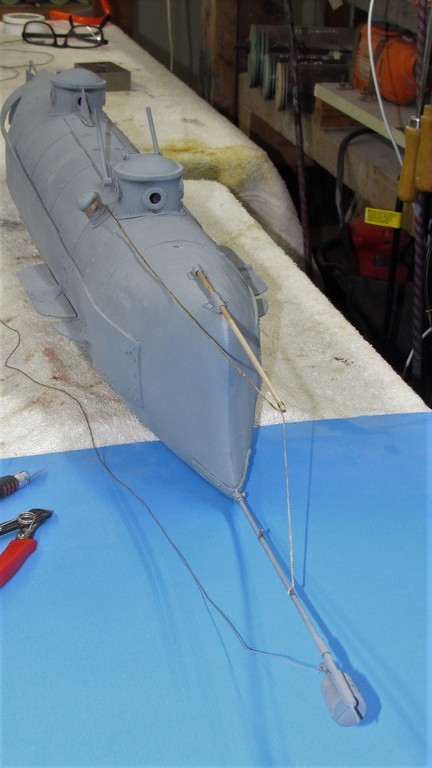
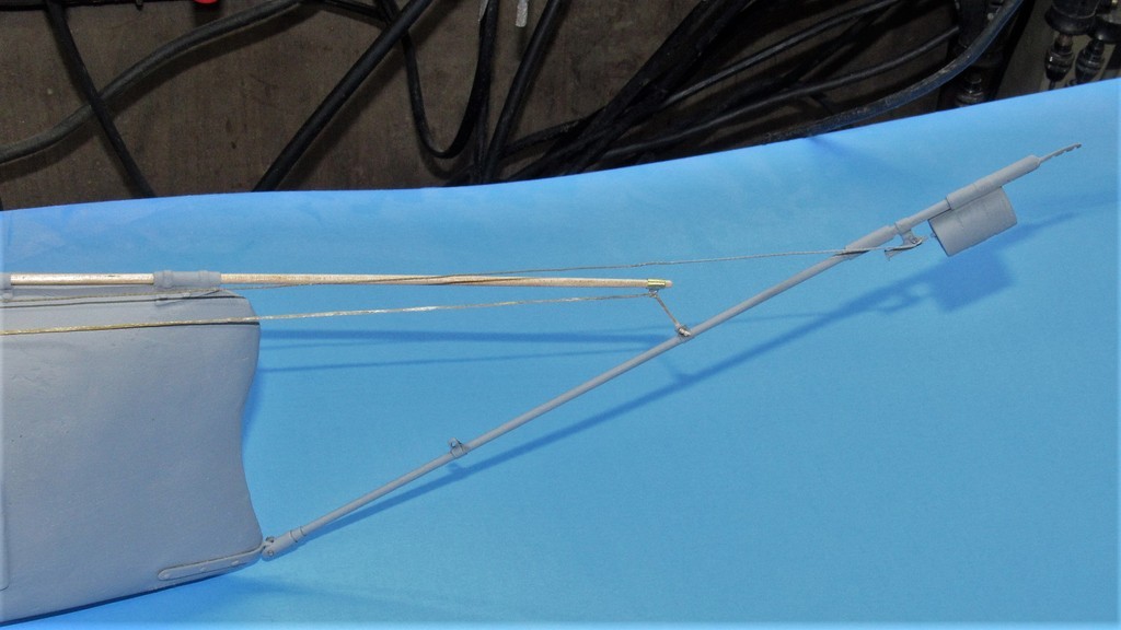

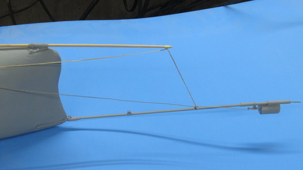
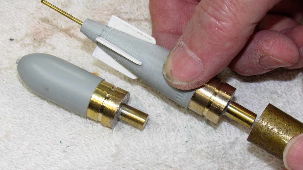

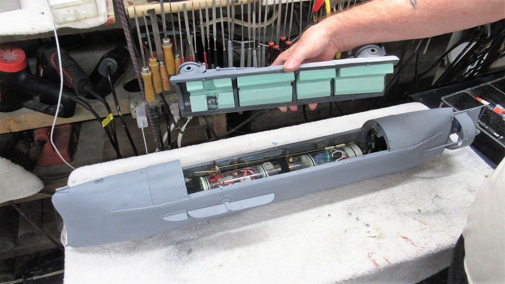

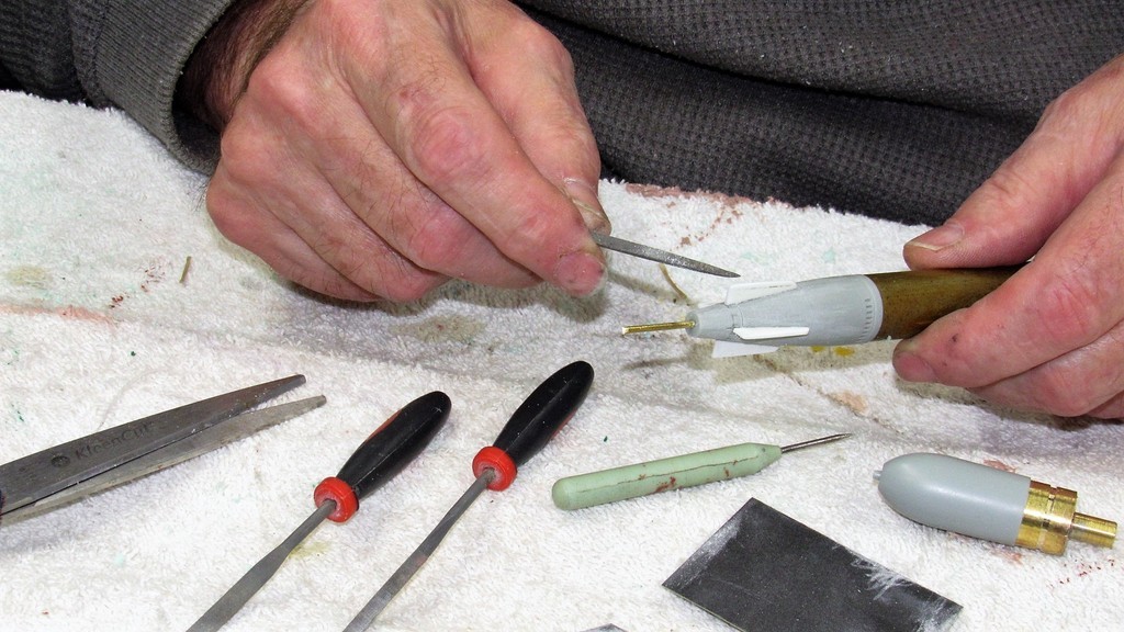


Similar threads
-
 General Theory of Optimal Combat Vehicle Design: A project
- Started by shin_getter
- Replies: 9
-

-
-
-
 UK deterrent with cruise missiles
- Started by uk 75
- Replies: 9